Science Arts & Métiers (SAM)
is an open access repository that collects the work of Arts et Métiers Institute of
Technology researchers and makes it freely available over the web where possible.
This is an author-deposited version published in: https://sam.ensam.eu Handle ID: .http://hdl.handle.net/10985/17487
To cite this version :
Faissal CHEGDANI, Satish BUKKAPATNAM, Mohamed EL MANSORI - Thermo-mechanical Effects in Mechanical Polishing of Natural Fiber Composites - In: 46th SME North American Manufacturing Research Conference, NAMRC 46, Texas, USA, Etats-Unis, 2018-06 - Procedia Manufacturing - 2018
Any correspondence concerning this service should be sent to the repository Administrator : archiveouverte@ensam.eu
ScienceDirect
Available online at Available online at www.sciencedirect.comwww.sciencedirect.com
ScienceDirect
Procedia Manufacturing 00 (2017) 000–000
www.elsevier.com/locate/procedia
* Paulo Afonso. Tel.: +351 253 510 761; fax: +351 253 604 741
E-mail address: psafonso@dps.uminho.pt
2351-9789 © 2017 The Authors. Published by Elsevier B.V.
Peer-review under responsibility of the scientific committee of the Manufacturing Engineering Society International Conference 2017.
Manufacturing Engineering Society International Conference 2017, MESIC 2017, 28-30 June
2017, Vigo (Pontevedra), Spain
Costing models for capacity optimization in Industry 4.0: Trade-off
between used capacity and operational efficiency
A. Santana
a, P. Afonso
a,*, A. Zanin
b, R. Wernke
ba University of Minho, 4800-058 Guimarães, Portugal bUnochapecó, 89809-000 Chapecó, SC, Brazil
Abstract
Under the concept of "Industry 4.0", production processes will be pushed to be increasingly interconnected, information based on a real time basis and, necessarily, much more efficient. In this context, capacity optimization goes beyond the traditional aim of capacity maximization, contributing also for organization’s profitability and value. Indeed, lean management and continuous improvement approaches suggest capacity optimization instead of maximization. The study of capacity optimization and costing models is an important research topic that deserves contributions from both the practical and theoretical perspectives. This paper presents and discusses a mathematical model for capacity management based on different costing models (ABC and TDABC). A generic model has been developed and it was used to analyze idle capacity and to design strategies towards the maximization of organization’s value. The trade-off capacity maximization vs operational efficiency is highlighted and it is shown that capacity optimization might hide operational inefficiency.
© 2017 The Authors. Published by Elsevier B.V.
Peer-review under responsibility of the scientific committee of the Manufacturing Engineering Society International Conference 2017.
Keywords: Cost Models; ABC; TDABC; Capacity Management; Idle Capacity; Operational Efficiency
1. Introduction
The cost of idle capacity is a fundamental information for companies and their management of extreme importance in modern production systems. In general, it is defined as unused capacity or production potential and can be measured in several ways: tons of production, available hours of manufacturing, etc. The management of the idle capacity
Procedia Manufacturing 26 (2018) 294–304
2351-9789 © 2018 The Authors. Published by Elsevier B.V.
Peer-review under responsibility of the scientific committee of the 4th International Conference on System-Integrated Intelligence. 10.1016/j.promfg.2018.07.038
10.1016/j.promfg.2018.07.038 2351-9789
© 2018 The Authors. Published by Elsevier B.V.
Peer-review under responsibility of the scientific committee of the 4th International Conference on System-Integrated Intelligence.
ScienceDirect
Procedia Manufacturing 00 (2018) 000–000
www.elsevier.com/locate/procedia
2351-9789 © 2018 The Authors. Published by Elsevier B.V.
Peer-review under responsibility of the scientific committee of NAMRI/SME.
46th SME North American Manufacturing Research Conference, NAMRC 46, Texas, USA
Thermo-mechanical Effects in Mechanical Polishing of Natural
Fiber Composites
Faissal Chegdani
a,b,*, Satish T.S. Bukkapatnam
a, Mohamed El Mansori
baTexas A&M University, Department of Industrial and Systems Engineering, 3131 TAMU, College Station, TX 77843, USA
bArts et Métiers ParisTech, MSMP Laboratory / EA7350, Rue Saint Dominique BP508, Châlons-en-Champagne, 51006, France
* Corresponding author. Tel.: +33 3 26 69 91 81. E-mail address: faissal.chegdani@ensam.eu
Abstract
Efficient machining and finishing of natural fiber reinforced plastic (NFRP) composites is essential for realizing the industrial application envisaged of these promising, environmentally friendly materials. While prior efforts allude to the multiscale nature of their material removal mechanisms, little understanding currently exists on the thermal effects of their material removal behaviors. This experimental study aims to characterize the thermal effects during the polishing of NFRP composites. For this aim, dry and wet polishing have been performed following several polishing steps on unidirectional flax fibers reinforced polypropylene composites. Results from scanning electron microscopy (SEM) and optical interferometry studies reveal a significant difference between dry and wet polishing in terms of surface artifacts induced. This difference is enhanced at higher sliding speed, indicating that the asperity removal during polishing is mostly thermally mediated. The results also indicate that the surface forming of flax fibers is related to the mechanical contact scale engendered by the grit size.
© 2018 The Authors. Published by Elsevier B.V.
Peer-review under responsibility of the scientific committee of NAMRI/SME.
Keywords: Natural fiber composites; Polymer matrix; Polishing process; Surface defects; Surface roughness; Material removal rate.
1. Introduction
Natural fiber reinforced plastic (NFRP) composites are eliciting increased interests for niche applications in the automotive and aerospace industry due to the combination of mechanical properties and sustainable options they can provide [1–3]. Mechanical properties
of some plant fibers, such as flax, hemp, ramie or jute, are comparable to those of synthetic glass fibers commonly used in industry in [2,4]. Moreover, plant fibers offer other benefits such as vibration damping [5,6], acoustic and thermal insulation [7]. NFRPs are biodegradable and recyclable whenever the matrix is of recyclable polymers. Therefore, the use of natural
2 F. Chegdani et al. / Procedia Manufacturing 00 (2018) 000–000
plant fibers in composite industry can be beneficial for the circular economy and the sustainable development [8].
Manufacturing components with NFRP
composites, especially with long fibers requires machining operations, such as drilling and milling, to realize the industrial parts. However, understanding of these operations is still in their infancy for NFRP composites. Indeed, prior experimental works on machining of NFRP have revealed challenges associated while cutting plant fibers inside composite materials [9–12]. This is due to complex structure of the fiber, along with the physical properties of the cellulosic material that comprises this structure [13]. A typical elementary fiber (Fig. 1(b)) consists of a stack of two cell walls arranged as concentric cylinders with a small channel in the middle called lumen [13]. Each cell wall is itself a composite of cellulose microfibrils and non-cellulosic polymer [14] as shown in Fig. 1(b).
In this context, the transversal flexibility of plant fibers induced by the cellulosic structure along the fiber axis poses a significant challenge for their cutting [12]. This complex structure gives them a multiscale behavior depending on the mechanical contact scale [15]. Consequently, some uncut fiber extremities remain on the machined surfaces of NFRP composite materials. Therefore, the use of finishing operations, such as polishing, will be mandatory to achieve the final industrial parts.
Polishing NFRP composites is not yet investigated to date. However, some works were interested in the
tribological behavior of NFRP composites using the pin-on-disc tribo test machine [16–21]. Indeed, it has been shown a better wear and frictional performance under wet contact condition compared to dry. The wear mechanisms, in this case, were predominated by micro and macro-cracks in the polymer regions and debonding of natural fibers [16]. It has been reported that the fiber orientation has a significant effect on wear and frictional performances in addition to the contact interface temperature [17]. The fiber content also determines the regions where an NFRP wears. Wear rates are drastically decreased with increasing fibers content [18]. The literature also indicates the importance of the fiber treatment; e.g. NaOH-treated NFRPs demonstrate improved wear performance as compared to their untreated counterparts [20]. Globally, the incorporation of natural fiber into polymer matrix improves significantly the tribological behavior of the composites by increasing the wear resistance and reducing the friction coefficient [19,21]. However, a pin-on-disc study remains a macro-tribological technique, as it is mainly based on sliding mechanism between two surfaces. It ignores the thermomechanical behavior of NFRP composites during material removal. Given the material properties (low thermal conductivity compared to metals) and high heat generation during material removal processes, consideration of thermomechanical effects is essential towards understanding the mechanisms of material removal in NFRPs.
Fig. 1. (a) Photograph of UDF/PP workpiece. (b) Schematic depiction of flax elementary fiber [14]
10 mm 10 mm 4 mm Raw worksurface Fiber orientation Primary cell wall Secondary cell wall Non cellulosic
polymer microfibrilCellulose
10 ~ 20 µm
a
b
Faissal Chegdani et al. / Procedia Manufacturing 26 (2018) 294–304 295
Available online at www.sciencedirect.com
ScienceDirect
Procedia Manufacturing 00 (2018) 000–000
www.elsevier.com/locate/procedia
2351-9789 © 2018 The Authors. Published by Elsevier B.V.
Peer-review under responsibility of the scientific committee of NAMRI/SME.
46th SME North American Manufacturing Research Conference, NAMRC 46, Texas, USA
Thermo-mechanical Effects in Mechanical Polishing of Natural
Fiber Composites
Faissal Chegdani
a,b,*, Satish T.S. Bukkapatnam
a, Mohamed El Mansori
baTexas A&M University, Department of Industrial and Systems Engineering, 3131 TAMU, College Station, TX 77843, USA
bArts et Métiers ParisTech, MSMP Laboratory / EA7350, Rue Saint Dominique BP508, Châlons-en-Champagne, 51006, France
* Corresponding author. Tel.: +33 3 26 69 91 81. E-mail address: faissal.chegdani@ensam.eu
Abstract
Efficient machining and finishing of natural fiber reinforced plastic (NFRP) composites is essential for realizing the industrial application envisaged of these promising, environmentally friendly materials. While prior efforts allude to the multiscale nature of their material removal mechanisms, little understanding currently exists on the thermal effects of their material removal behaviors. This experimental study aims to characterize the thermal effects during the polishing of NFRP composites. For this aim, dry and wet polishing have been performed following several polishing steps on unidirectional flax fibers reinforced polypropylene composites. Results from scanning electron microscopy (SEM) and optical interferometry studies reveal a significant difference between dry and wet polishing in terms of surface artifacts induced. This difference is enhanced at higher sliding speed, indicating that the asperity removal during polishing is mostly thermally mediated. The results also indicate that the surface forming of flax fibers is related to the mechanical contact scale engendered by the grit size.
© 2018 The Authors. Published by Elsevier B.V.
Peer-review under responsibility of the scientific committee of NAMRI/SME.
Keywords: Natural fiber composites; Polymer matrix; Polishing process; Surface defects; Surface roughness; Material removal rate.
1. Introduction
Natural fiber reinforced plastic (NFRP) composites are eliciting increased interests for niche applications in the automotive and aerospace industry due to the combination of mechanical properties and sustainable options they can provide [1–3]. Mechanical properties
of some plant fibers, such as flax, hemp, ramie or jute, are comparable to those of synthetic glass fibers commonly used in industry in [2,4]. Moreover, plant fibers offer other benefits such as vibration damping [5,6], acoustic and thermal insulation [7]. NFRPs are biodegradable and recyclable whenever the matrix is of recyclable polymers. Therefore, the use of natural
2 F. Chegdani et al. / Procedia Manufacturing 00 (2018) 000–000
plant fibers in composite industry can be beneficial for the circular economy and the sustainable development [8].
Manufacturing components with NFRP
composites, especially with long fibers requires machining operations, such as drilling and milling, to realize the industrial parts. However, understanding of these operations is still in their infancy for NFRP composites. Indeed, prior experimental works on machining of NFRP have revealed challenges associated while cutting plant fibers inside composite materials [9–12]. This is due to complex structure of the fiber, along with the physical properties of the cellulosic material that comprises this structure [13]. A typical elementary fiber (Fig. 1(b)) consists of a stack of two cell walls arranged as concentric cylinders with a small channel in the middle called lumen [13]. Each cell wall is itself a composite of cellulose microfibrils and non-cellulosic polymer [14] as shown in Fig. 1(b).
In this context, the transversal flexibility of plant fibers induced by the cellulosic structure along the fiber axis poses a significant challenge for their cutting [12]. This complex structure gives them a multiscale behavior depending on the mechanical contact scale [15]. Consequently, some uncut fiber extremities remain on the machined surfaces of NFRP composite materials. Therefore, the use of finishing operations, such as polishing, will be mandatory to achieve the final industrial parts.
Polishing NFRP composites is not yet investigated to date. However, some works were interested in the
tribological behavior of NFRP composites using the pin-on-disc tribo test machine [16–21]. Indeed, it has been shown a better wear and frictional performance under wet contact condition compared to dry. The wear mechanisms, in this case, were predominated by micro and macro-cracks in the polymer regions and debonding of natural fibers [16]. It has been reported that the fiber orientation has a significant effect on wear and frictional performances in addition to the contact interface temperature [17]. The fiber content also determines the regions where an NFRP wears. Wear rates are drastically decreased with increasing fibers content [18]. The literature also indicates the importance of the fiber treatment; e.g. NaOH-treated NFRPs demonstrate improved wear performance as compared to their untreated counterparts [20]. Globally, the incorporation of natural fiber into polymer matrix improves significantly the tribological behavior of the composites by increasing the wear resistance and reducing the friction coefficient [19,21]. However, a pin-on-disc study remains a macro-tribological technique, as it is mainly based on sliding mechanism between two surfaces. It ignores the thermomechanical behavior of NFRP composites during material removal. Given the material properties (low thermal conductivity compared to metals) and high heat generation during material removal processes, consideration of thermomechanical effects is essential towards understanding the mechanisms of material removal in NFRPs.
Fig. 1. (a) Photograph of UDF/PP workpiece. (b) Schematic depiction of flax elementary fiber [14]
10 mm 10 mm 4 mm Raw worksurface Fiber orientation Primary cell wall Secondary cell wall Non cellulosic
polymer microfibrilCellulose
10 ~ 20 µm
a
b
This paper presents a longitudinal experimental study and subsequent SEM imaging [22] to capture the thermal effects on material removal and surface modification during the polishing of flax fibers reinforced polypropylene composites. Polishing process was investigated under both dry and wet conditions, as well as under varying sliding speeds in order to tune the thermal conditions at polishing contact interface. The grit size of abrasive papers is changed at each polishing step to explore the mechanical contact scale. The microscopic surface state is revealed by scanning electron microscope (SEM) and the defect zones of each surface are estimated based on Mesurim Pro © software using the SEM images. The material removal induced by the polishing process is evaluated by measuring the material removal rate. The polished surface topography is acquired using an optical interferometer.
2. Experimental setup
Unidirectional flax fibers reinforced polypropylene (UDF/PP) composite workpieces (see Fig. 1(a)) manufactured and supplied by “Composites Evolution – UK” are employed for this study. The fiber volume fraction is 40% and the fiber unidirectionality is maintained by polyester weft fiber with low volume fraction (around 5%). More technical data of UDF/PP composites is given in [12].
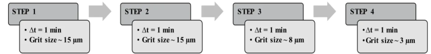
The workpieces are polished at both dry and wet conditions on a Buehler Metaserv Grinder-Polisher (model 95-C2348-160) with silicon carbide (SiC) abrasive papers and following progressive polishing steps as described in Fig. 2. During each polishing step, the UDF/PP workpiece was hand-held at the same position from the abrasive paper center in order to perform with constant sliding speed (V). Thus, three sliding speed values are considered (4.5, 18, and 27 m/min). The wet condition is performed with water. The water flow (~1.65 ml/s) is introduced on the abrasive paper during the polishing operation.
After each polishing step, the workpiece weight is measured using a microbalance to determine the
material removal rate (MRR). The polished surfaces state is evaluated by scanning electron microscope (Zeiss SEM – model EVO/MA10) at low vacuum mode (40 Pa of chamber pressure). SEM images are taken at different locations on the polished surfaces after each step. Then, typical representative surface morphology as induced by polishing is hence presented in this study.
Moreover, the topography of the polished surfaces is rated by an optical interferometer (model ZYGO/14-21-75092) using a magnification of ×10. Topographic images are taken in five different location of each polished surface to determine the arithmetical mean height of the surface (Sa) following the ISO 25178 standard.
To get reliable results, each considered polishing test is repeated three times under identical conditions and with a new SiC abrasive paper at each time. Thus, the output values from the mechanical polishing experiments are presented as the mean of these three repeated tests. Errors are considered as the average of the absolute deviations of data repeatability tests from their mean.
3. Results and discussions
3.1. Surface modification at microscale
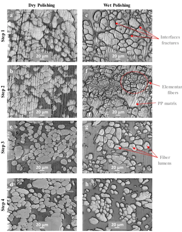
Fig. 3 shows typical microscopic surfaces state after each polishing step. The only difference between the micrographs from step 1 and step 2 is the increasing of polishing streaks. This is mostly due to the effect of polishing time since step 1 and step 2 are performed with the same grit size. However, it can be seen a significant difference between dry and wet polishing. Indeed, at wet polishing, the cross-sections of elementary flax fibers are well obvious with the fiber shape and the lumen. On the other side, dry polishing shows deformed cross-sections of flax fibers and the fiber lumens are difficult to observe. Nevertheless, wet polishing shows a high incidence of fractures of fiber/fiber interfaces and fiber/matrix interfaces. STEP 1 • ∆t = 1 min • Grit size ~ 15 µm STEP 2 • ∆t = 1 min • Grit size ~ 15 µm STEP 3 • ∆t = 1 min • Grit size ~ 8 µm STEP 4 •∆t = 1 min •Grit size ~ 3 µm Fig. 2. Schematic description of the progressive polishing process
By continuing the next polishing steps (3 then 4), the polishing streaks disappear progressively and the cross-sections of flax fibers are well obvious. However, reducing the grit size in step 3 then step 4 makes the lumen to disappear which means that the fibers cross-sections are more deformed by reducing
the polishing grit size. It can also be noticed that reducing the grit size reduces the interfaces fracture.
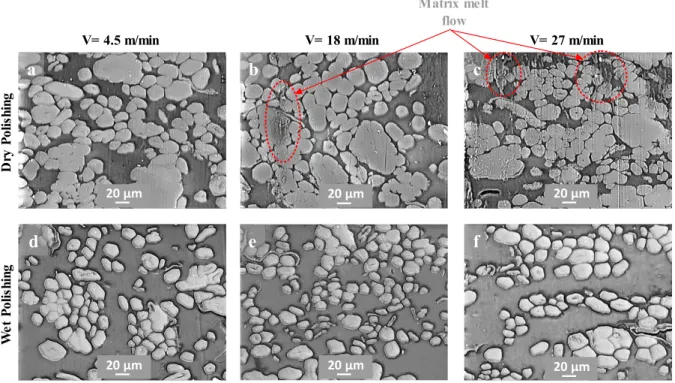
Fig. 4 shows the sliding speed effect on the microscopic surface state which is significantly obvious for dry polishing. Indeed, there is a matrix melt flow spread on the polished surface. The flow
Fig. 3. SEM images of the polished surfaces at V = 4.5 m/min showing the effect of each polishing step
St ep 1 St ep 2 St ep 3 St ep 4
Dry Polishing Wet Polishing
a
b
c
d
e
f
g
h
Interfaces fractures Elementary fibers PP matrix Fiber lumens 20 µm 20 µm 20 µm 20 µm 20 µm 20 µm 20 µm 20 µmFaissal Chegdani et al. / Procedia Manufacturing 26 (2018) 294–304 297
F. Chegdani et al. / Procedia Manufacturing 00 (2018) 000–000 3
This paper presents a longitudinal experimental study and subsequent SEM imaging [22] to capture the thermal effects on material removal and surface modification during the polishing of flax fibers reinforced polypropylene composites. Polishing process was investigated under both dry and wet conditions, as well as under varying sliding speeds in order to tune the thermal conditions at polishing contact interface. The grit size of abrasive papers is changed at each polishing step to explore the mechanical contact scale. The microscopic surface state is revealed by scanning electron microscope (SEM) and the defect zones of each surface are estimated based on Mesurim Pro © software using the SEM images. The material removal induced by the polishing process is evaluated by measuring the material removal rate. The polished surface topography is acquired using an optical interferometer.
2. Experimental setup
Unidirectional flax fibers reinforced polypropylene (UDF/PP) composite workpieces (see Fig. 1(a)) manufactured and supplied by “Composites Evolution – UK” are employed for this study. The fiber volume fraction is 40% and the fiber unidirectionality is maintained by polyester weft fiber with low volume fraction (around 5%). More technical data of UDF/PP composites is given in [12].
The workpieces are polished at both dry and wet conditions on a Buehler Metaserv Grinder-Polisher (model 95-C2348-160) with silicon carbide (SiC) abrasive papers and following progressive polishing steps as described in Fig. 2. During each polishing step, the UDF/PP workpiece was hand-held at the same position from the abrasive paper center in order to perform with constant sliding speed (V). Thus, three sliding speed values are considered (4.5, 18, and 27 m/min). The wet condition is performed with water. The water flow (~1.65 ml/s) is introduced on the abrasive paper during the polishing operation.
After each polishing step, the workpiece weight is measured using a microbalance to determine the
material removal rate (MRR). The polished surfaces state is evaluated by scanning electron microscope (Zeiss SEM – model EVO/MA10) at low vacuum mode (40 Pa of chamber pressure). SEM images are taken at different locations on the polished surfaces after each step. Then, typical representative surface morphology as induced by polishing is hence presented in this study.
Moreover, the topography of the polished surfaces is rated by an optical interferometer (model ZYGO/14-21-75092) using a magnification of ×10. Topographic images are taken in five different location of each polished surface to determine the arithmetical mean height of the surface (Sa) following the ISO 25178 standard.
To get reliable results, each considered polishing test is repeated three times under identical conditions and with a new SiC abrasive paper at each time. Thus, the output values from the mechanical polishing experiments are presented as the mean of these three repeated tests. Errors are considered as the average of the absolute deviations of data repeatability tests from their mean.
3. Results and discussions
3.1. Surface modification at microscale
Fig. 3 shows typical microscopic surfaces state after each polishing step. The only difference between the micrographs from step 1 and step 2 is the increasing of polishing streaks. This is mostly due to the effect of polishing time since step 1 and step 2 are performed with the same grit size. However, it can be seen a significant difference between dry and wet polishing. Indeed, at wet polishing, the cross-sections of elementary flax fibers are well obvious with the fiber shape and the lumen. On the other side, dry polishing shows deformed cross-sections of flax fibers and the fiber lumens are difficult to observe. Nevertheless, wet polishing shows a high incidence of fractures of fiber/fiber interfaces and fiber/matrix interfaces. STEP 1 • ∆t = 1 min • Grit size ~ 15 µm STEP 2 • ∆t = 1 min • Grit size ~ 15 µm STEP 3 • ∆t = 1 min • Grit size ~ 8 µm STEP 4 •∆t = 1 min •Grit size ~ 3 µm Fig. 2. Schematic description of the progressive polishing process
4 F. Chegdani et al. / Procedia Manufacturing 00 (2018) 000–000
By continuing the next polishing steps (3 then 4), the polishing streaks disappear progressively and the cross-sections of flax fibers are well obvious. However, reducing the grit size in step 3 then step 4 makes the lumen to disappear which means that the fibers cross-sections are more deformed by reducing
the polishing grit size. It can also be noticed that reducing the grit size reduces the interfaces fracture.
Fig. 4 shows the sliding speed effect on the microscopic surface state which is significantly obvious for dry polishing. Indeed, there is a matrix melt flow spread on the polished surface. The flow
Fig. 3. SEM images of the polished surfaces at V = 4.5 m/min showing the effect of each polishing step
St ep 1 St ep 2 St ep 3 St ep 4
Dry Polishing Wet Polishing
a
b
c
d
e
f
g
h
Interfaces fractures Elementary fibers PP matrix Fiber lumens 20 µm 20 µm 20 µm 20 µm 20 µm 20 µm 20 µm 20 µmintensity increases with an increase in sliding speed. This phenomenon is inherently related to the thermal effect produced during the polishing contact. Indeed, increases the sliding speed increases the strain rate during both material removal and plastic deformation when polishing. Thus, material temperature increases by increases the strain rate caused by the sliding speed. Moreover, the matrix melt flow is only obvious in step 4 where some particles on the matrix surface undergo a large plastic deformation because of the high polishing temperature and remain on the
composite surface as debris (Fig. 4(c)). Indeed, in step 4, the grit size is the lowest and, then, the real polishing contact surface is the highest which leads to increase the surface contact temperature. Observations of such a thermal effect have not been reported in the literature, and it can lead to new models to capture material and asperity removal for these novel materials.
Fig. 4. SEM images of the polished surfaces at Step 4 showing the effect of sliding speed
D ry P ol is hi ng W et P ol is hi ng
V= 4.5 m/min V= 18 m/min V= 27 m/min
a
d
b
e
c
f
Matrix melt flow 20 µm 20 µm 20 µm 20 µm 20 µm 20 µmFig. 5. SEM image of polished surface (a) before processing and (b) after processing by Mesurim Pro ©
a
b
Interfaces
fractures Interfaces fractures
20 µm 20 µm
3.2. Surface defect intensity
Interface fracture is among the significant issues when processing inhomogeneous materials. Indeed, the interfacial micro-fractures present a surface defect and can lead to an initiation of cracks in the industrial part during service. Thus, the evaluation of these fracture zones that present the fractures of fiber/fiber interfaces, fiber/matrix interfaces, and the matrix fracture must be investigated to better predict the material performances after processing.
Towards this end, fracture zones are identified from the SEM images taken from three different locations of each polished surface using Mesurim Pro software (Version 3.4 ©) by detecting the dark areas of fractures as shown in Fig. 5. The fracture zone rate (FZ) is then calculated as the ratio between the fracture zone area (SFZ), measured in terms of the
number of pixels in yellow color in Fig. 5(b), and the total surface area (STOT), measured in terms of the
total number of pixels, as follows:
FZ (%) = (SFZ / STOT) × 100 (1)
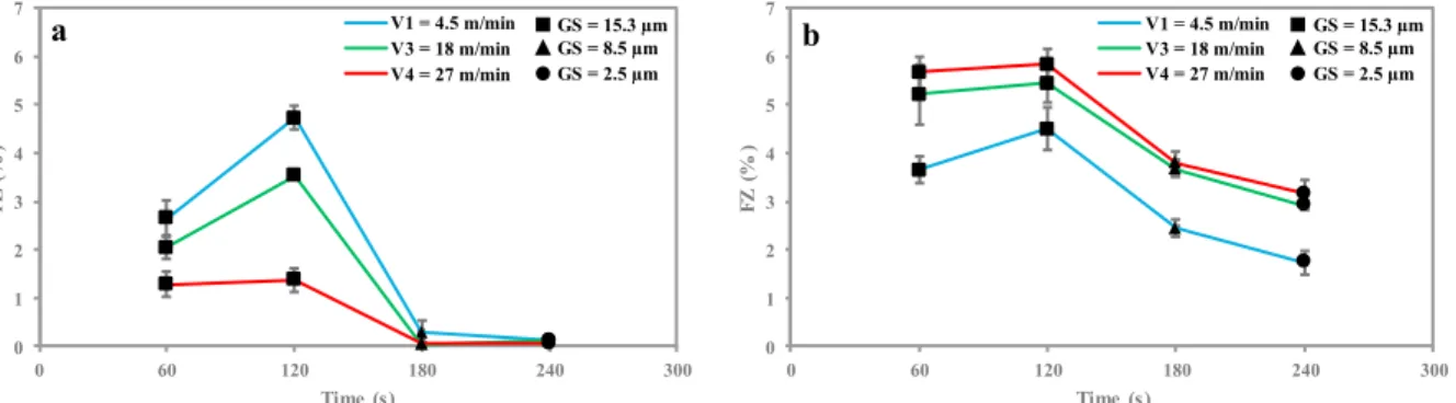
Fig. 6 shows the fracture zone rate (FZ) for the different polishing conditions. Globally, the wet polishing generates more FZ than the dry polishing. FZ increases from step 1 to step 2 and drastically decreases from step 2 to step 3. FZ decreasing continue from step 3 to step 4. In step 4, FZ is almost zero for the dry polishing while it remains considerable for the wet polishing.
Fig. 6 demonstrates that the sliding speed effect depends on the polishing condition. In dry polishing, increasing the sliding speed decreases the FZ. However, in wet polishing, increasing the sliding
speed increases the FZ. Indeed, when the polishing process is performed in dry condition, the thermal effect controls the tribo-contact behavior because increasing the sliding speed increases the temperature in the contact interface. Generally, the NFRP elasticity decreases by increasing the temperature. This effect is more significant from glass transition temperature that is around 0°C (similar to that of PP matrix) [23]. Thus, the PP matrix controls the thermal behavior of the NFRP as it is the responsible for supporting fibers and inside the composites.
The thermal effect leads to increase the viscoelasticity of both PP matrix and the thermoplastic chemical components of flax fibers. Indeed, the Vicat softening temperature of PP matrix is around 90-118°C [24,25]. The Vicat softening temperature is the temperature at which a flat-ended needle of 1 mm² circular cross-section area penetrates the thermoplastic specimen to the depth of 1 mm under a specific load [24]. This temperature reflects the point of softening to be expected when a material is used in an elevated temperature application. Thus, the softening temperature of PP is easily attainable at 1 min of dry polishing and this will increase the viscoelasticity of the matrix which leads to avoid a brittle crack initiation in PP matrix. Moreover, the viscosity of PP matrix is strongly dependent on the temperature. Indeed, the PP viscosity is three times reduced when increasing the temperature from 170°C to 200°C [26].
Flax fibers are mainly composed of cellulose microfibrils, hemicellulose, and lignin which are the general chemical composition of plant fibers [13]. In flax fibers, increasing temperatures lead to water release and degradation of cellulosic and non-cellulosic substances [27]. Lignin and hemicellulose are the amorphous non-cellulosic polymers shown in
0 1 2 3 4 5 6 7 0 60 120 180 240 300 FZ ( % ) Time (s) V1 = 4.5 m/min V3 = 18 m/min V4 = 27 m/min 0 1 2 3 4 5 6 7 0 60 120 180 240 300 FZ ( % ) Time (s) V1 = 4.5 m/min V3 = 18 m/min V4 = 27 m/min a GS = 15.3 µm GS = 8.5 µm GS = 2.5 µm b GS = 15.3 µm GS = 8.5 µm GS = 2.5 µm
Faissal Chegdani et al. / Procedia Manufacturing 26 (2018) 294–304 299
F. Chegdani et al. / Procedia Manufacturing 00 (2018) 000–000 5
intensity increases with an increase in sliding speed. This phenomenon is inherently related to the thermal effect produced during the polishing contact. Indeed, increases the sliding speed increases the strain rate during both material removal and plastic deformation when polishing. Thus, material temperature increases by increases the strain rate caused by the sliding speed. Moreover, the matrix melt flow is only obvious in step 4 where some particles on the matrix surface undergo a large plastic deformation because of the high polishing temperature and remain on the
composite surface as debris (Fig. 4(c)). Indeed, in step 4, the grit size is the lowest and, then, the real polishing contact surface is the highest which leads to increase the surface contact temperature. Observations of such a thermal effect have not been reported in the literature, and it can lead to new models to capture material and asperity removal for these novel materials.
Fig. 4. SEM images of the polished surfaces at Step 4 showing the effect of sliding speed
D ry P ol is hi ng W et P ol is hi ng
V= 4.5 m/min V= 18 m/min V= 27 m/min
a
d
b
e
c
f
Matrix melt flow 20 µm 20 µm 20 µm 20 µm 20 µm 20 µmFig. 5. SEM image of polished surface (a) before processing and (b) after processing by Mesurim Pro ©
a
b
Interfaces
fractures Interfaces fractures
20 µm 20 µm
6 F. Chegdani et al. / Procedia Manufacturing 00 (2018) 000–000
3.2. Surface defect intensity
Interface fracture is among the significant issues when processing inhomogeneous materials. Indeed, the interfacial micro-fractures present a surface defect and can lead to an initiation of cracks in the industrial part during service. Thus, the evaluation of these fracture zones that present the fractures of fiber/fiber interfaces, fiber/matrix interfaces, and the matrix fracture must be investigated to better predict the material performances after processing.
Towards this end, fracture zones are identified from the SEM images taken from three different locations of each polished surface using Mesurim Pro software (Version 3.4 ©) by detecting the dark areas of fractures as shown in Fig. 5. The fracture zone rate (FZ) is then calculated as the ratio between the fracture zone area (SFZ), measured in terms of the
number of pixels in yellow color in Fig. 5(b), and the total surface area (STOT), measured in terms of the
total number of pixels, as follows:
FZ (%) = (SFZ / STOT) × 100 (1)
Fig. 6 shows the fracture zone rate (FZ) for the different polishing conditions. Globally, the wet polishing generates more FZ than the dry polishing. FZ increases from step 1 to step 2 and drastically decreases from step 2 to step 3. FZ decreasing continue from step 3 to step 4. In step 4, FZ is almost zero for the dry polishing while it remains considerable for the wet polishing.
Fig. 6 demonstrates that the sliding speed effect depends on the polishing condition. In dry polishing, increasing the sliding speed decreases the FZ. However, in wet polishing, increasing the sliding
speed increases the FZ. Indeed, when the polishing process is performed in dry condition, the thermal effect controls the tribo-contact behavior because increasing the sliding speed increases the temperature in the contact interface. Generally, the NFRP elasticity decreases by increasing the temperature. This effect is more significant from glass transition temperature that is around 0°C (similar to that of PP matrix) [23]. Thus, the PP matrix controls the thermal behavior of the NFRP as it is the responsible for supporting fibers and inside the composites.
The thermal effect leads to increase the viscoelasticity of both PP matrix and the thermoplastic chemical components of flax fibers. Indeed, the Vicat softening temperature of PP matrix is around 90-118°C [24,25]. The Vicat softening temperature is the temperature at which a flat-ended needle of 1 mm² circular cross-section area penetrates the thermoplastic specimen to the depth of 1 mm under a specific load [24]. This temperature reflects the point of softening to be expected when a material is used in an elevated temperature application. Thus, the softening temperature of PP is easily attainable at 1 min of dry polishing and this will increase the viscoelasticity of the matrix which leads to avoid a brittle crack initiation in PP matrix. Moreover, the viscosity of PP matrix is strongly dependent on the temperature. Indeed, the PP viscosity is three times reduced when increasing the temperature from 170°C to 200°C [26].
Flax fibers are mainly composed of cellulose microfibrils, hemicellulose, and lignin which are the general chemical composition of plant fibers [13]. In flax fibers, increasing temperatures lead to water release and degradation of cellulosic and non-cellulosic substances [27]. Lignin and hemicellulose are the amorphous non-cellulosic polymers shown in
0 1 2 3 4 5 6 7 0 60 120 180 240 300 FZ ( % ) Time (s) V1 = 4.5 m/min V3 = 18 m/min V4 = 27 m/min 0 1 2 3 4 5 6 7 0 60 120 180 240 300 FZ ( % ) Time (s) V1 = 4.5 m/min V3 = 18 m/min V4 = 27 m/min a GS = 15.3 µm GS = 8.5 µm GS = 2.5 µm b GS = 15.3 µm GS = 8.5 µm GS = 2.5 µm
Fig. 1(b) and are much more thermoplastic than cellulose, which is a highly crystalline polymer. The softening temperature turns around 127-235 °C for lignin and 167-217 °C for hemicellulose [28]. If the polishing contact interface reaches these temperature values, the amorphous components of flax fibers will be more viscoelastic near to the contact interface and, then, the cross-section of polished fibers could be easily deformed by the thermomechanical effect to form a new cross-section shape. This is exactly what has been happened at dry polishing condition from the first step where the fiber lumens disappear from the cross-section of fibers, contrary to the wet polishing as described in Fig. 3 and Section 3.1. This proves that the softening temperatures of hemicellulose and lignin are reached from step 1 and low sliding speed at dry polishing. Therefore, reaching the softening temperature of PP matrix, hemicellulose and lignin will increase the ductility of the fibers, the matrix and the interfaces at the polished
surface and, then, avoid the brittle crack of the interfaces between fibers and PP matrix.
On the other hand, during wet polishing, the thermal effect is significantly reduced. Thus, the phenomena arising at the contact interface will be purely mechanical since increasing the sliding speed increases the frictional stresses without any material softening. Consequently, the fibers/matrix interfaces will undergo micro-cracking on the polished surface because of the weak mechanical properties of these fibers/matrix interfaces.
In addition, water absorption can affect the natural fibers by reducing the mechanical properties and damaging the interfaces between fibers and matrix in wet polishing [4]. However, to have enough water uptake into flax fibers that allow mechanical damage, NFRP composites should be exposed to water for a long time (> 1 hour) either in room temperature or boiling temperature [29,30]. In this study, the samples are exposed to the water for just one minute at each Fig. 7. Typical topographic images at V = 27 m/min for (a) wet polishing at step 1, (b) wet polishing at step 4, (c) dry polishing at step 1,
(d) dry polishing at step 4
1.4 µm - 1.4 µm 800µm 0 200 400 600 3.1 µm - 2.9 µm 800µm 0 200 400 600 1.1 µm - 1.1 µm 800µm 0 200 400 600 1.8 µm - 1.9 µm 800µm 0 200 400 600
a
b
c
d
Flax fibers PP matrix Flax fibers PP matrix Interfaces fractures Matrix melt flowstep. Therefore, the effect of water absorption can be significant on the interfaces but not for the fibers themselves.
The grit size effect is related to the multiscale mechanical behavior of natural fibers inside the composite material. Indeed, the stiffness of flax fibers is highly dependent on the mechanical contact scale because of their multiscale cellulosic structure [15]. Increasing the contact scale increases the fiber stiffness by taking into account a high rate of cellulosic microfibrils in the mechanical contact [15]. Thus, polishing with grit size of ~ 15 µm will generate a micro-contact scale corresponding to the flax fiber cross-section size (around 10-20 µm). Decreasing the grit size (to 8 µm and then 3 µm) decreases the mechanical contact scale to be inside
the elementary fiber which will decreases the fiber stiffness during the polishing contact. Consequently, the loss of rigidity favors the ductility of the fibers at the contact surface which can avoid the brittle crack of the fibers/matrix interfaces.
3.3. Polishing induced surface finish 3.3.1. Polished surfaces topography
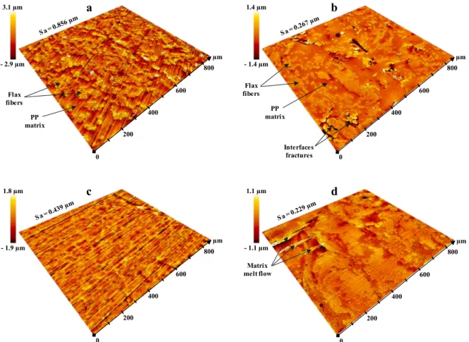
Fig. 7 shows typical topographic images of the polished surfaces. The thermomechanical phenomena demonstrated in Section 3.1 and Section 3.2 can be observed in the surface topography images. Fig. 7(a) and Fig. 7(c) show the high polishing streaks induced by the high grit size. Fig. 7(b) shows also the fracture zones on the fibers/matrix interfaces induced by wet polishing. Fig. 7(d) shows the matrix melt flow due to the thermal effect of dry polishing. In Fig. 7(a) and Fig. 7(c), it can be observed that the height difference between flax fibers and PP matrix is more important for wet polishing. Indeed, wet polishing with high grit size is performed with high flax fiber stiffness due to the high contact scale generated during the polishing process as explained in Section 3.2. The high fibers stiffness prevents the fibers deformation and increases the fibers spring-back after the polishing contact. PP matrix is plastically deformed as it has a poor stiffness comparing to flax fibers and, thus, its spring-back is very low. This can explain the height difference between flax fibers and PP matrix when polishing with high grit size at wet conditions. When decreasing the grit size, the fiber stiffness decreases and, consequently, the fiber spring-back. Therefore, the height difference between flax fibers and PP matrix decreases when decreasing the polishing grit size.
3.3.2. Polished surface roughness
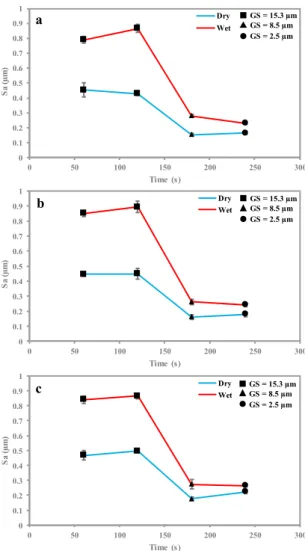
The overall phenomena discussed in Section 3.3.1 affect the mean surface roughness as shown in Fig. 8. Polishing with high grit size induces the highest surface roughness because of polishing streaks and fracture zones. These two factors decrease significantly by decreasing the grit size and, consequently, the surface roughness also decreases significantly.
Wet polishing induces more surface roughness than dry polishing because of the high fracture zones produced by wet polishing. However, the surface roughness difference between dry and wet polishing is more obvious when the grit size is high. This is due
0 0.1 0.2 0.3 0.4 0.5 0.6 0.7 0.8 0.9 1 0 50 100 150 200 250 300 Sa (µ m) Time (s) Dry Wet 0 0.1 0.2 0.3 0.4 0.5 0.6 0.7 0.8 0.9 1 0 50 100 150 200 250 300 Sa ( µm ) Time (s) Dry Wet 0 0.1 0.2 0.3 0.4 0.5 0.6 0.7 0.8 0.9 1 0 50 100 150 200 250 300 Sa (µ m) Time (s) Dry Wet GS = 15.3 µm GS = 8.5 µm GS = 2.5 µm GS = 15.3 µm GS = 8.5 µm GS = 2.5 µm GS = 15.3 µm GS = 8.5 µm GS = 2.5 µm a b c
Fig. 8. Mean arithmetic surface roughness of polished surfaces at (a) V = 4.5 m/min, (b) V = 18 m/min, (c) V = 27
Faissal Chegdani et al. / Procedia Manufacturing 26 (2018) 294–304 301
F. Chegdani et al. / Procedia Manufacturing 00 (2018) 000–000 7
Fig. 1(b) and are much more thermoplastic than cellulose, which is a highly crystalline polymer. The softening temperature turns around 127-235 °C for lignin and 167-217 °C for hemicellulose [28]. If the polishing contact interface reaches these temperature values, the amorphous components of flax fibers will be more viscoelastic near to the contact interface and, then, the cross-section of polished fibers could be easily deformed by the thermomechanical effect to form a new cross-section shape. This is exactly what has been happened at dry polishing condition from the first step where the fiber lumens disappear from the cross-section of fibers, contrary to the wet polishing as described in Fig. 3 and Section 3.1. This proves that the softening temperatures of hemicellulose and lignin are reached from step 1 and low sliding speed at dry polishing. Therefore, reaching the softening temperature of PP matrix, hemicellulose and lignin will increase the ductility of the fibers, the matrix and the interfaces at the polished
surface and, then, avoid the brittle crack of the interfaces between fibers and PP matrix.
On the other hand, during wet polishing, the thermal effect is significantly reduced. Thus, the phenomena arising at the contact interface will be purely mechanical since increasing the sliding speed increases the frictional stresses without any material softening. Consequently, the fibers/matrix interfaces will undergo micro-cracking on the polished surface because of the weak mechanical properties of these fibers/matrix interfaces.
In addition, water absorption can affect the natural fibers by reducing the mechanical properties and damaging the interfaces between fibers and matrix in wet polishing [4]. However, to have enough water uptake into flax fibers that allow mechanical damage, NFRP composites should be exposed to water for a long time (> 1 hour) either in room temperature or boiling temperature [29,30]. In this study, the samples are exposed to the water for just one minute at each Fig. 7. Typical topographic images at V = 27 m/min for (a) wet polishing at step 1, (b) wet polishing at step 4, (c) dry polishing at step 1,
(d) dry polishing at step 4
1.4 µm - 1.4 µm 800µm 0 200 400 600 3.1 µm - 2.9 µm 800µm 0 200 400 600 1.1 µm - 1.1 µm 800µm 0 200 400 600 1.8 µm - 1.9 µm 800µm 0 200 400 600
a
b
c
d
Flax fibers PP matrix Flax fibers PP matrix Interfaces fractures Matrix melt flow8 F. Chegdani et al. / Procedia Manufacturing 00 (2018) 000–000
step. Therefore, the effect of water absorption can be significant on the interfaces but not for the fibers themselves.
The grit size effect is related to the multiscale mechanical behavior of natural fibers inside the composite material. Indeed, the stiffness of flax fibers is highly dependent on the mechanical contact scale because of their multiscale cellulosic structure [15]. Increasing the contact scale increases the fiber stiffness by taking into account a high rate of cellulosic microfibrils in the mechanical contact [15]. Thus, polishing with grit size of ~ 15 µm will generate a micro-contact scale corresponding to the flax fiber cross-section size (around 10-20 µm). Decreasing the grit size (to 8 µm and then 3 µm) decreases the mechanical contact scale to be inside
the elementary fiber which will decreases the fiber stiffness during the polishing contact. Consequently, the loss of rigidity favors the ductility of the fibers at the contact surface which can avoid the brittle crack of the fibers/matrix interfaces.
3.3. Polishing induced surface finish 3.3.1. Polished surfaces topography
Fig. 7 shows typical topographic images of the polished surfaces. The thermomechanical phenomena demonstrated in Section 3.1 and Section 3.2 can be observed in the surface topography images. Fig. 7(a) and Fig. 7(c) show the high polishing streaks induced by the high grit size. Fig. 7(b) shows also the fracture zones on the fibers/matrix interfaces induced by wet polishing. Fig. 7(d) shows the matrix melt flow due to the thermal effect of dry polishing. In Fig. 7(a) and Fig. 7(c), it can be observed that the height difference between flax fibers and PP matrix is more important for wet polishing. Indeed, wet polishing with high grit size is performed with high flax fiber stiffness due to the high contact scale generated during the polishing process as explained in Section 3.2. The high fibers stiffness prevents the fibers deformation and increases the fibers spring-back after the polishing contact. PP matrix is plastically deformed as it has a poor stiffness comparing to flax fibers and, thus, its spring-back is very low. This can explain the height difference between flax fibers and PP matrix when polishing with high grit size at wet conditions. When decreasing the grit size, the fiber stiffness decreases and, consequently, the fiber spring-back. Therefore, the height difference between flax fibers and PP matrix decreases when decreasing the polishing grit size.
3.3.2. Polished surface roughness
The overall phenomena discussed in Section 3.3.1 affect the mean surface roughness as shown in Fig. 8. Polishing with high grit size induces the highest surface roughness because of polishing streaks and fracture zones. These two factors decrease significantly by decreasing the grit size and, consequently, the surface roughness also decreases significantly.
Wet polishing induces more surface roughness than dry polishing because of the high fracture zones produced by wet polishing. However, the surface roughness difference between dry and wet polishing is more obvious when the grit size is high. This is due
0 0.1 0.2 0.3 0.4 0.5 0.6 0.7 0.8 0.9 1 0 50 100 150 200 250 300 Sa (µ m) Time (s) Dry Wet 0 0.1 0.2 0.3 0.4 0.5 0.6 0.7 0.8 0.9 1 0 50 100 150 200 250 300 Sa ( µm ) Time (s) Dry Wet 0 0.1 0.2 0.3 0.4 0.5 0.6 0.7 0.8 0.9 1 0 50 100 150 200 250 300 Sa (µ m) Time (s) Dry Wet GS = 15.3 µm GS = 8.5 µm GS = 2.5 µm GS = 15.3 µm GS = 8.5 µm GS = 2.5 µm GS = 15.3 µm GS = 8.5 µm GS = 2.5 µm a b c
Fig. 8. Mean arithmetic surface roughness of polished surfaces at (a) V = 4.5 m/min, (b) V = 18 m/min, (c) V = 27
to the fibers spring-back as explained in Section 3.3.1.
The effect of sliding speed on the surface roughness seems to be insignificant because of its reverse effects. Indeed, as explained in Section 3.1 and Section 3.2, increasing the sliding speed when performing a dry polishing reduces the fracture zones and, at the same time, increases the matrix melt flow by thermal effect. The effects of these two phenomena offset each other in the mean surface roughness values. This can explain the insignificance of sliding speed in the induced surface roughness. 3.4. Material removal rate
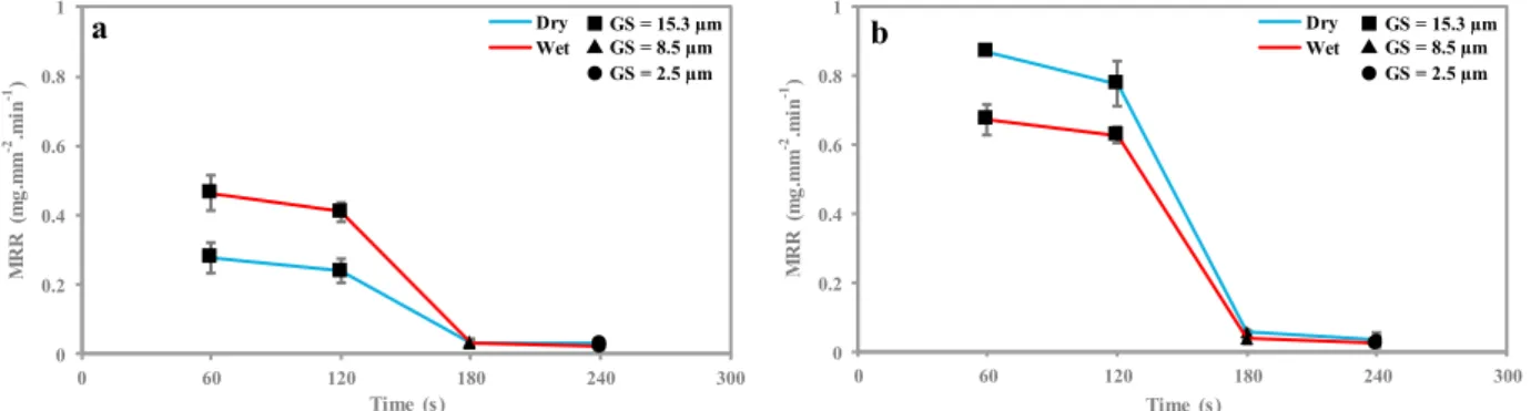
Fig. 9 presents the material removal rate (MRR) during the polishing procedure. It shows that the material removal mechanism occurs mainly by high grit size (~15 µm). Decreasing the grit size to 8 µm decreases drastically the MRR and no significant difference is then observed by decreasing the grit size to 3 µm. This behavior can be explained by the notion of minimum chip thickness. Indeed, the concept of minimum chip thickness is that the depth of cut must be over a certain critical chip thickness before a chip will form and then the material will be removed [31]. In the case of polishing, increasing the grit size increases the penetration depth of the abrasive grains which will increase the removal chip thickness. Once the chip thickness reaches the minimum critical value, the material shearing will be the overriding mechanism against plastic deformation, sliding and plowing.
Fig. 9 shows also that increasing the sliding speed increases the MRR by simply increasing the sliding distance. Moreover, the effect of polishing condition (dry or wet) is undeniably related to the sliding speed. Indeed, when polishing with low sliding
speed, wet polishing produces the highest MRR. However, when polishing with high sliding speed, dry polishing produces the highest MRR. This reverse effect is due to the thermal influence caused by increasing the sliding speed. Increasing the sliding speed increases the contact interface temperature during dry polishing which makes the material softer (Section 3.2) and then easy to be removed. This can explain the drastic increase in the MRR by increasing the sliding speed at dry polishing condition.
4. Conclusions
The mechanical polishing process has been performed on unidirectional flax fibers reinforced polypropylene composites to investigate the thermal effect on surface formation during several steps of polishing by testing dry and wet conditions. Prior investigations, as noted earlier, ignored the thermal effects on MRR, surface defects, and surface roughness.
The following conclusions can be drawn from our experimental study:
Dry polishing induced fewer surface defects in the composite surface. This is due to the temperature increase that makes the material softer and, thereby, avoids the brittle fracture of the fibers/matrix interfaces.
Increasing the sliding speed at dry polishing increases the contact temperature that exceeds the melting temperature of polypropylene. This produces a matrix melt flow on the polished surfaces and also avoids the brittle crack of the fibers/matrix interfaces. However, increasing the sliding speed at wet polishing increases the fracture zones by increasing the friction forces. The effect of the polishing grit size is related to
the multiscale mechanical behavior of flax fibers.
0 0.2 0.4 0.6 0.8 1 0 60 120 180 240 300 M R R ( mg .mm -2.mi n -1) Time (s) Dry Wet 0 0.2 0.4 0.6 0.8 1 0 60 120 180 240 300 M R R ( mg .mm -2.mi n -1) Time (s) Dry Wet GS = 15.3 µmGS = 8.5 µm GS = 2.5 µm GS = 15.3 µm GS = 8.5 µm GS = 2.5 µm a b
Fig. 9. Material removal rate after each polishing step at (a) V = 4.5 m/min and (b) V = 27 m/min
Decreasing the grit size below the elementary fiber diameter size affects the mechanical contact scale during polishing by decreasing the contact stiffness. This controls the surface formation of flax fibers through plastic deformation of their natural cross-sections.
The effect of polishing condition (dry or wet) affects surfaces roughness where dry polishing generates smoother surfaces than wet polishing. Material removal is higher at the wet condition
when polishing with low sliding speed (4.5 m/min for a speed range of [4.5 – 27 m/min]). However, high sliding speed (27 m/min) makes the material removal larger under the dry condition. This is due to the thermal effect induced by sliding speed that makes the material softer.
References
[1] E. Omrani, P. L. Menezes, P. K. Rohatgi, State of the art on tribological behavior of polymer matrix composites reinforced with natural fibers in the green materials world, Eng. Sci. Technol. an Int. J. 19 (2016) 717–736. doi:10.1016/J.JESTCH.2015.10.007.
[2] K.L. Pickering, M.G. Aruan Efendy, T.M. Le, A review of recent developments in natural fibre composites and their mechanical performance, Compos. Part A Appl. Sci. Manuf. 83 (2016) 98–112.
doi:10.1016/J.COMPOSITESA.2015.08.038.
[3] A. Shalwan, B.F. Yousif, In State of Art: Mechanical and tribological behaviour of polymeric composites based on natural fibres, Mater. Des. 48 (2013) 14–24.
doi:10.1016/j.matdes.2012.07.014.
[4] D.B. Dittenber, H.V.S. GangaRao, Critical review of recent publications on use of natural composites in infrastructure, Compos. Part A Appl. Sci. Manuf. 43 (2012) 1419–1429.
doi:10.1016/j.compositesa.2011.11.019. [5] A. Etaati, S.A. Mehdizadeh, H. Wang, S. Pather,
Vibration damping characteristics of short hemp fibre thermoplastic composites, J. Reinf. Plast. Compos. 33 (2014) 330–341. doi:10.1177/0731684413512228. [6] G. Rajeshkumar, V. Hariharan, Free Vibration
Characteristics of Phoenix Sp Fiber Reinforced Polymer Matrix Composite Beams, Procedia Eng. 97 (2014) 687– 693. doi:10.1016/J.PROENG.2014.12.298.
[7] C. Alves, P.M.C. Ferrao, A.J. Silva, L.G. Reis, M. Freitas, L.B. Rodrigues, D.E. Alves, Ecodesign of automotive components making use of natural jute fiber composites, J. Clean. Prod. 18 (2010) 313–327.
doi:10.1016/J.JCLEPRO.2009.10.022.
[8] M. Ramesh, K. Palanikumar, K. Hemachandra Reddy, Plant fibre based bio-composites: Sustainable and renewable green materials, Renew. Sustain. Energy Rev. 79 (2017) 558–584. doi:10.1016/J.RSER.2017.05.094. [9] F. Chegdani, S. Mezghani, M. El Mansori, A. Mkaddem,
Fiber type effect on tribological behavior when cutting natural fiber reinforced plastics, Wear. 332–333 (2015) 772–779. doi:10.1016/j.wear.2014.12.039.
[10] F. Chegdani, S. Mezghani, M. El Mansori, Correlation between mechanical scales and analysis scales of topographic signals under milling process of natural fibre composites, J. Compos. Mater. 51 (2017) 2743–2756. doi:10.1177/0021998316676625.
[11] F. Chegdani, S. Mezghani, M. El Mansori, On the multiscale tribological signatures of the tool helix angle in profile milling of woven flax fiber composites, Tribol. Int. 100 (2016) 132–140.
doi:10.1016/j.triboint.2015.12.014.
[12] F. Chegdani, S. Mezghani, M. El Mansori, Experimental study of coated tools effects in dry cutting of natural fiber reinforced plastics, Surf. Coatings Technol. 284 (2015) 264–272. doi:10.1016/j.surfcoat.2015.06.083. [13] C. Baley, Analysis of the flax fibres tensile behaviour
and analysis of the tensile stiffness increase, Compos. - Part A Appl. Sci. Manuf. 33 (2002) 939–948. doi:10.1016/S1359-835X(02)00040-4.
[14] A. Lefeuvre, A. Bourmaud, L. Lebrun, C. Morvan, C. Baley, A study of the yearly reproducibility of flax fiber tensile properties, Ind. Crops Prod. 50 (2013) 400–407. doi:10.1016/j.indcrop.2013.07.035.
[15] F. Chegdani, M. El Mansori, S. Mezghani, A. Montagne, Scale effect on tribo-mechanical behavior of vegetal fibers in reinforced bio-composite materials, Compos. Sci. Technol. 150 (2017) 87–94.
doi:10.1016/j.compscitech.2017.07.012. [16] B.F. Yousif, S.T.W. Lau, S. McWilliam, Polyester
composite based on betelnut fibre for tribological applications, Tribol. Int. 43 (2010) 503–511. doi:10.1016/J.TRIBOINT.2009.08.006.
[17] U. Nirmal, J. Hashim, K.O. Low, Adhesive wear and frictional performance of bamboo fibres reinforced epoxy composite, Tribol. Int. 47 (2012) 122–133. doi:10.1016/J.TRIBOINT.2011.10.012.
[18] M. Bakry, M.O. Mousa, W.Y. Ali, Friction and wear of friction composites reinforced by natural fibres, Materwiss. Werksttech. 44 (2013) 21–28. doi:10.1002/mawe.201300962.
[19] T.B. Yallew, P. Kumar, I. Singh, Sliding Wear Properties of Jute Fabric Reinforced Polypropylene Composites, Procedia Eng. 97 (2014) 402–411.