Science Arts & Métiers (SAM)
is an open access repository that collects the work of Arts et Métiers Institute of
Technology researchers and makes it freely available over the web where possible.
This is an author-deposited version published in:
https://sam.ensam.eu
Handle ID: .
http://hdl.handle.net/10985/7216
To cite this version :
Anna DUPLEIX, Sid' Ahmed OULD AHMEDOU, Laurent BLERON, Frédéric ROSSI, Mark
HUGHES - Rational production of veneer by IR-heating of green wood during peeling: Modeling
experiments - Holzforschung - Vol. 67, n°1, p.53-58 - 2013
Any correspondence concerning this service should be sent to the repository
Administrator :
archiveouverte@ensam.eu
during peeling: Modeling experiments
Anna Dupleix
1,*, Sid ’ Ahmed Ould Ahmedou
1,
Laurent Bleron
1, Fr é d é ric Rossi
1and Mark Hughes
21
Arts et Metiers ParisTech LaBoMaP , Rue Porte de Paris,
F-71250 Cluny , France
2
School of Chemical Technology , Department of Forest
Products Technology, Aalto University, FI-00076 Aalto ,
Finland
* Corresponding author.
Arts et Metiers ParisTech LaBoMaP, Rue Porte de Paris, F-71250 Cluny, France
Phone: + 33 (0)3 85 59 53 27 Fax: + 33 (0)3 85 59 53 85 E-mail: anna.dupleix@ensam.eu
Abstract
Heating green wood logs by infrared (IR) radiation during
peeling for veneer production has been numerically simulated,
focusing on the heating kinetics of a green wood cylinder
rotating with a decreasing radius. The results confi rm those of
previous experiments, that this kind of heating is a promising
alternative to soaking wood prior to peeling. The model
inte-grates the green wood parameters such as moisture content,
density, distribution and ratios of earlywood and latewood, on
the one hand, and the peeling conditions of veneer thickness
and peeling speed, on the other. The following heat transfer
processes were considered: conduction within the bolt,
exter-nal heating by the IR source, and convection between the bolt
surface and the external environment. The outputs were the
temperatures of the bolt surface and of layers several
milli-meters deep. For maximal heat penetration, the bolt should turn
in front of the IR source before cutting starts and the IR source
should be positioned at the greatest angular distance ahead of
the knife. Several heating scenarios could be simulated by the
model, thus it is a useful decision-making tool for the design of
an in-line IR heating system installed on the peeling lathe.
Keywords: green wood; heating; infrared; modeling; peeling
for veneer production.
Introduction
For industrial veneer production, bolts are heated by soaking or
steaming prior to peeling, which increases mechanical
deform-ability of wood by softening the lignin moiety (Baldwin 1975 ;
Matsunaga and Minato 1998 ; Bardet et al. 2003 ; Yamauchi
et al. 2005 ). Water, as an integral part of wood, makes it an
ideal medium for heat transfer into green wood. This kind of
pretreatment also reduces the risk of lathe checking,
amelio-rates veneer surface quality, and lowers cutting forces and
power consumption. Thermoforming of wood veneers was
discussed by Srinivasan et al. (2007) and the complex
inter-relation between cutting forces in wood machining was
reviewed by Marchal et al. (2009) . In the same context, the
properties of wood surfaces and the fracture behavior of wood
was summarized by Sinn et al. (2009) and Stanzl -Tschegg and
Navi (2009) , respectively. The mechanical behavior of thin
veneers is a special issue, as pointed out recently by Buchelt
and Pfriem (2011) and Kl ü ppel and Mai (2012) .
The softening of knots contributes to preservation of cutting
tool wear (Marchal et al. 2004 ). Heating alone is also utile,
but soaking in water is benefi cial because of the
improve-ment of color homogeneity of decorative veneers. However,
soaking is an empirical process performed between 32
° C and
90
° C (Baldwin 1975 ) and it has also some disadvantages, for
example: (1) the long treatment time (12 – 72 h); (2) the
wash-ing out of extractable matter, which leads to water pollution
and affects the natural durability of wood; (3) an increase in
bolt-end splitting, which reduces bolt cohesion; and (4) the
requirement for large soaking basins and sophisticated
han-dling, i.e., the investment costs are high.
This is the reason why alternative heating solutions are
sought for. Experiments with electric ohmic and microwave
heating methods (Torgovnikov and Vinden 2010 ) have
dem-onstrated that the “softening ” effect does not depend on
heat-ing time, but only on the wood temperature attained, i.e.,
wood softening does not necessitate “ cooking” for a long time
as was thought before (Lutz 1960 ). A promising solution is a
local heating of the surface just ahead of the knife, to a depth
equal to the thickness of the veneer produced (Marchal and
Collet 2000 ). An IR heating system may be the most suitable
technology in terms of rapid heating rates and such a system
is easy to install on the peeling lathe (Coste 2005 ).
Recently, it has been demonstrated that lower bolt surface
temperatures of around 50
° C for beech, birch, Douglas-fi r,
and spruce, were suffi cient for acceptable peeling (Dupleix
et al. 2011 ). It was established that IR radiation is suitable for
heating green wood surfaces up to a depth of several
millime-tres (Gaudilliere 2003 ). A fi nite-difference method has
dem-onstrated that living trees are heated via IR radiation (Potter
and Andresen 2010 ). However, the promising experimental
results of the quoted authors have not been confi rmed by any
numerical simulation under conditions of dynamic movement
of the log in terms of IR induced heating rates.
The intention of the present paper is to fi ll this gap and to
model IR heating of logs under industrial conditions of veneer
production. The technical feasibility of an in-line IR heating
system [Figure 1 (a)] is a challenge. The principal issue is the
2 A. Dupleix et al.
ability of IR heating to raise the temperature of the surface
of a rotating bolt to a certain value, within the shortest
pos-sible time (depending on the peeling speed) and to a deepness
needed for peeling. On the other hand, overheating should be
avoided, which would lead to quality defects on the surface.
An open question is, whether suffi cient heating of the cutting
plane is achievable under industrial peeling conditions. In the
industry, peeling speeds, depths and heating temperatures vary
as a function of wood species and the end use of the veneers.
In the present study, the following parameters were
con-sidered as acceptable under industrial conditions: a minimum
temperature of 50
° C achieved on the cutting plane located up
to 3 mm depth and peeling speeds between 1 to 10 ms
-1. The
expectation is that modeling the heating of green wood by IR
during peeling, will abbreviate the fi nding of the best process
conditions in practice.
Materials and methods
Methodology
Software for equation solution: Comsol Multiphysics (Comsol Inc., Burlington, MA, USA), a partial differential equations solver based on the fi nite element (FE) method, with the overall proce-dure implemented under the fl exible MatLab (MathWorks Inc.,
Natick, MA, USA). This approach offers the following advantages: (1) generating an appropriate and easy-to-modify FE geometry; (2) facilitating the implementation of intrinsic model properties (physical, optical, thermal, structural, etc.) to its geometrical parameters and mesh; and (3) solving partial differential equations with Comsol Multiphysics.
Confi guration
The bolt was modeled in 2D, i.e., the cross-section (radial and trans-versal directions) whilst the bolt length (the longitudinal direction) can be varied and does not play any role in heat transfer. The IR source was applied locally to the surface of the bolt as depicted in Figure 1(a). The cross-section was meshed by Lagrange-quadratic elements with triangular shapes as the basic functions. To predict heat transfer accurately in the vicinity of the bolt surface, the non-uniform mesh is close to the bolt surface and the cutting plane [Figure 1(b)]. Meshing actually occurs on the whole bolt cross-section, but meshing limited only to the external ring of the bolt up to a suffi cient depth might also be considered, if speeding up the calculations is necessary.
A sensitivity analysis indicated that with a minimum element size of 0.7 mm in the bolt cross-section, a mesh density > 3 elements per mm 2 would be required to obtain a mesh-independent solution. This
is illustrated through the evolution of temperature at a point located on the bolt surface according to mesh density [Figure 1(c)]. For mesh density > 3 elements per mm 2 , there is no infl uence of the refi nement
on the resulting temperatures.
Peeling knife IR heater Longitudinal Tangential Radial 0.1 0.08 26 25 24 23 Temperature ( °C) 22 21 20 0.0015 2 4 6 8
Mesh density (elements/mm2)
10 12 0.06 0.04 0.02 0 -0.02 -0.02 0 0.02 x (m) x (m) x (m) y (m) IR 0.04 0.06 0.08 0.1 -0.04 -0.04 -0.06 -0.06 -0.08 -0.08 -0.1 0.1 0.08 Earlywood
a
c
d
b
Latewood 0.06 0.04 0.02 -0.02 -0.04 -0.06 -0.08 -0.061.2 kg/m3 (air) 900 kg/m3 (earlywood) 1200 kg/m3 (latewood)
-0.04 -0.02 0 0.02 0.04 0.06 0.08 0.1 0.08 0.1 Peeling knife Bolt rotation -0.08 -0.1 -0.1 0 -0.1
Figure 1 Modeling of IR on-line heating of logs for veneer production. (a) Principle of surface heating, (b) fi ner mesh close to the bolt surface, (c) infl uence of mesh-density refi nement on results and (d) modeling the surface layer removal, when a peeling of a bolt is defi ned by subdomain parametric settings (case of off-centered pith) – densities on display.
Equations
The temperature distribution within the bolt cross-section is governed by the transient heat transfer equation for conduction according to Eq. (1) derived from Fourier ’ s law. This equation only considers IR radiation absorbed by wood surface, and it does not integrate IR pen-etrated to deeper wood layers (volumetric absorption). The boundary conditions for temperature at the bolt surface are given by Neumann conditions (-n (- λ∇ T) = Q rad ) with n normal vector to the boundary. Eq. (2) takes into account heat losses due to convection and exter-nal input heat due to radiation from the IR source Q rad and adiabatic conditions elsewhere: ∂ ρ ∇ λ∇ ∂ p T C = ( T) t (1)
4 4
rad ext ext
Q =h(T -T)+εσ(T -T ) (2)
where C p is the heat capacity of the wood (in J kg -1 K -1 ), T ext the
external IR source temperature (in K), T is the bolt temperature (in K), λ the conductivity of wood (in W m -1 K -1 ), ε is the wood
emis-sivity and σ is Stefan-Boltzmann ’ s constant (in W m -2 K -4 ). The heat
transfer coeffi cient, h, is fi xed at 5 W m -2 K -1 (Qu é m é ner et al. 2003 ).
The mean value ε = 0.85 is chosen because unplaned wood emissi vity is said to vary from 0.70 to 0.98 for temperatures ranging from 17 to 70 ° C (Flir Systems 2004 ). However, moisture content (MC) is not detailed in these values and the emissivity of green wood would need to be characterized more carefully. Wood emissivity here is in-dependent of the IR wavelength (total emissivity) because the whole emission spectrum of the IR source determined by T ext is taken into account (Planck ’ s law).
Subdomain settings
The cross-section of the bolt is divided into subdomains, with spe-cifi c initial settings in terms of structural properties – earlywood (EW), latewood (LW) – physical properties (density ρ in kg m -3 ) and
thermal properties (C p , λ ). All parameters considered to describe the bolt structure, such as bolt diameter, annual ring width, heartwood ring width, latewood ring width, and pith eccentricity, are defi ned by modifi able input values. Different physical and thermal proper-ties of wood, ρ , C p , and λ , are then applied to the different wood substructures concerning EW and LW and as functions of their MC conditions [Figure 1(d)]. Structural properties such as heartwood/ sapwood, wood rays, and knots have not been taken into account in this model. It is likely that structural properties infl uence heat trans-fer into wood, because of their variations in densities and therefore in thermal characteristics. Distinguishing heartwood from sapwood could be integrated in the present mesh, contrary to inserting wood rays and knots, which would necessitate modifying the geometry and the mesh of the model. But given the lack of data concerning their variations in thermal characteristics, defi nitions of wood structural properties are limited to variations of densities. For this reason, only the infl uence of MC at 12 % , 40 % , and 72 % on IR heating of green wood is considered in this study. However, thermal properties of wood above the fi ber saturation point (FSP) are not available in the literature and are considered as constant at MCs higher than FSP, but a precise characterization of thermal properties of wood above the FSP would be necessary. In all other simulations, MC is set to 72 % (saturated state) with corresponding physical and thermal properties for wood (Table 1 ).
Table 1 Thermal and physical properties concerning density ( ρ ), conductivity ( λ ), and heat capacity (Cp) of earlywood (EW) and latewood (LW) as a function of their moisture content (MC) according to Glass and Zelinka (2010) for wood species with specifi c densities for earlywood of 0.60 and for latewood of 0.70.
Parameter EW LW ρ (kg cm -3 ) at 12 % MC 672 784 at 40 % MC 840 980 at 72 % MC 1066 1204 λ (W m -1 K -1 ) at 12 % MC 0.164 0.189 at 40 % MC 0.196 0.226 at 72 % MC 0.196 0.226 Cp (kJ kg -1 K -1 ) at 12 % MC 2000 3000 at 40 % MC 2700 3500 at 72 % MC 2700 3500 Boundary setting
The bolt surface is divided into 360 sections with uniform boundary settings. Only the IR source external input Q rad (in W m -2 ) defi ned
with the external IR source temperature T ext [Eq. (2)] is successively activated with a Boolean operator for each section, with S i of the bolt surface being radiated. Q rad is applied on a constant number of segments during the whole cutting process. Technical solutions on the peeling lathe are: (1) either the IR source is kept at a constant distance from the bolt and equipped with a defl ector able to concen-trate radiation with a varying angle on specifi c bolt segments, or (2) the IR source with a fi xed spectrum width adapts its distance to the bolt surface according to the bolt ’ s decreasing radius. The distance between the peeling knife and the IR source is defi ned by the angle θ [Figure 1(d)].
Modeling
For geometric convenience, the real situation was converted by sup-posing an immobile bolt with an IR heat source turning around it. The relative movement of the IR source and wood to each other is impor-tant. On the one hand, the model can simulate only heating of a bolt rotating in front of an IR source without cutting it [Figure 2 (a), right path]. In that case, no removal of material is induced and sub domain settings are constant with time. On the other hand, left path in Figure 2(a) simulates IR heating of a rotating bolt while peeling. The continu-ous removal of a wood surface layer by peeling is modeled by turning the physical properties of each cut segment from wood to air. In Figure 1(d), segments in blue featuring 1.2 kg m -3 density represent air, i.e.,
segments that have been cut from the bolt. In that case, subdomain settings are functions of time and are automatically modifi ed with Boolean functions. At each angular step, each element of the angular section S i reaches a new temperature achieved, due to the input of the external IR source and calculated with Eqs. (1) and (2). After each angular step, the IR is moved (by modifying boundary settings) and the last heated section is removed (by turning its density to air density). After each turn, the fi nal calculated temperature of each element is used as the initial temperature of the new meshing element at the bolt surface. In contrast to a real peeling process, where the cutting knife trajectory draws spirals, the model is simplifi ed to the removal of a cylinder of veneer upon every complete rotation. This approximation
4 A. Dupleix et al. Surface 1 mm-depth 2 mm-depth Surface Time (s) Time (s) Temperature (°C) Temperature (°C) 1 mm-depth 2 mm-depth
a
b
d
c
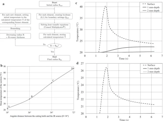
Figure 2 Details of modeling the IR heating during peeling. (a) fl ow chart of the numerical procedure, (b) infl uence of the angular distance θ between knife and IR source (T ext = 2500 ° C, v = 0.3 ms -1 , bolt diameter = 20 cm, MC = 72 % , θ = 18 ° ), (c) and (d) temporal evolution of temperature
within the bolt during one turn of external heating for T ext = 500 ° C, bolt diameter = 20 cm, and MC = 72 % ; however for (c) v = 0.1 ms -1 and for
(d) v = 1 ms -1 .
only affects the distance between the IR source and the bolt surface to a negligible extent – to that of the veneer thickness – without a signifi -cant infl uence on the numerical simulation of heat transfer .
Results and discussion
Figures 2(c) and 2(d) show the temporal evolution of
tem-perature during one turn of a rotating bolt initially at 20
° C
and heated by external IR radiation at a source temperature
T
ext= 500 ° C and for cutting speeds of 0.1 ms
-1and 1 ms
-1,
respectively. The results provide information on the heat
transfer behavior deep within the bolt and support 2-step
heating kinetics (Bedard and Laganiere 2009 ). Firstly, the IR
energy is absorbed at the wood surface to a negligible
pen-etration depth [dashed curve in Figure 2(c)]. Considering the
hypothesis of surface absorption (see Equations), IR heat is
then partly lost to the surroundings by convection and partly
transferred towards the interior of the bolt by conduction
to the deeper layers [black and gray curves in Figure 2(c)].
However, the 2 mm-deep layers never benefi t from heat by
conduction. This delay in temperature rise corresponds to the
time-lapse that must necessarily occur between the heating
and cutting stages and can be interpreted geometrically to
determine the optimum angular position of the IR source as
a function of the bolt diameter. In the present setting [Figure
2(c)], 3 s are necessary to raise the temperature of a 1
mm-deep layer to the maximum value achievable by conduction of
heat from the surface (from t
= 1.5 s to t = 4.5 s). In the present
case, for a cutting speed of 0.1 ms
-1and a bolt of 20 cm
diam-eter, these 3 s would be achieved if the IR source is located at
an angle of 170
° ahead of the cutting knife.
Distance between knife and IR source
Figure 2(b) confi rms the infl uence of the angular distance
θ between the cutting knife and the IR source (in the
pres-ent case,
θ = 18 ° ). Clearly, the further the knife is from the
IR source, the more time is needed for heat penetration into
the bolt, and therefore, the higher must be the temperature.
Temperatures in Figure 2(b) are mean values within each
seg-ment A, B, C, and D for source temperature T
ext= 2500 ° C and
peeling speed v
= 0.3 ms
-1.
Peeling speeds and source temperatures
Varying peeling speeds (0.1, 0.5, and 1 ms
-1) and source
tem-peratures (500, 1500, and 2500
° C) lead to the same 2-step heat
transfer behavior as shown in Figures 2(c) and 2(d) [Figures
3 (a) and 3(b)]. The high amount of energy absorbed at the
bolt surface is transferred by conduction to the adjacent layers
beneath. Logically, heating rates decrease with higher peeling
speed, thicker veneer thickness and lower IR source
tempera-ture [Figures 2(c), 2(d), 3(a) and 3(b)]. Approaching industrial
peeling speeds at around 1 ms
-1, the time is too short to enable
heat transfer by conduction from the surface to deeper layers.
For peeling speeds above 0.5 ms
-1, the temperature rise in the
2 mm-deep layer becomes effectively insignifi cant as shown
in Figure 3b. Increasing the source temperature from 500 to
2500
° C does not improve this situation; it only leads to the
risk of the bolt surface burning with the maximum of curves
reaching temperatures above 300
° C.
Rotation without cutting
For the above-mentioned reasons, a possibility was
inves-tigated, in which the bolt was left turning in front of the IR
source before cutting starts. This would allow more time for
heat transfer into deeper layers. Figures 3a and 3b illustrate the
temperature evolution within the bolt as a function of the
num-ber of rotations for peeling speeds of 0.1, 0.5, 1 ms
-1and source
temperature T
ext= 500 ° C. At depths of 1 mm [Figure 3(a)] and
2 mm [Figure 3(b)], the temperature rise is perceptible.
Figure 3(c) illustrates this situation (continuous curve)
before cutting starts on the 6
th
turn (dashed curve). The
temperature evolution as a function of the number of turns
is given for a “ fl oating ’ ’ layer always located at 2 mm deep
from the cutting plane, therefore, at varying bolt diameters
detailed in the data labels. These simulations provide
infor-mation about the temperatures achievable at the cutting plane,
where cutting is interrupted by heating stages. This solution
could only be considered for slicing (non-continuous cutting
process) but not for the continuous peeling process. However,
the confi guration of the heating system should be optimized
to adapt it to realistic slicing speeds (approx. 1 ms
-1) with
heating source temperatures, which would not lead to burning
of the surface.
Infl uence of MC
Figure 3(d) illustrates the infl uence of MC on temperature
ele-vation at local points of the bolt surface, for a source
tempera-ture of 2500
° C. Firstly, for the same amount of energy from
the IR source, the fi nal temperature reached at the bolt surface
Figure 3 Temperature evolution as a function of turn number for bolts with 20 cm diameter. (a) T ext = 500 ° C, e = 1 mm, variable cutting speeds, (b) T ext = 500 ° C, e = 2 mm, variable cutting speeds, (c) constant 2 mm depth, T ext = 2500 ° C, v = 0.1 ms -1 , (d ) temperature elevation at the bolt
6 A. Dupleix et al.
is lower when the MC is higher. Then, the time required to
reach the maximum surface temperature is longer when the
MC is higher. Figure 3(d) illustrates that the infl uence of MC
on wood heating can be predicted by means of parametric
defi nitions of the physical properties of wood. Given the
sig-nifi cant infl uence of MC, it might be of interest, in the future,
to integrate mass transfer equations in the model to take into
account the effect of drying during heating. Although the
pre-sented model does not take into account the heterogeneity of
wood, it clearly shows the roles that various parameters play
in infl uencing heat transfer. It is particularly the case
concern-ing the infl uence of MC on wood heat transfer.
Conclusions
The simulation provides information on the optimum confi
g-uration of the IR heating system, to achieve the temperatures
required on the cutting plane. Firstly, to ensure heat
penetra-tion up to the cutting plane, it is necessary to let the bolt turn in
front of the IR source before cutting starts. The model enables
calculation of the number of turns before cutting commences,
according to the peeling settings. Then, the position of the IR
source can be geometrically determined as a function of the
time calculated by the model for heat transfer from the bolt
surface to adjacent layers. Given the signifi cant losses due
to convection to the exterior environment and the relatively
slow conduction process, the IR source should be located as
far as possible from the knife. The presented model could be
a part of an essential decision-making tool, prior to the design
of in-line IR heating system directly embedded on the cutting
machine. The results support the utilization of IR heating for
slicing processes. Experimental data are needed for validating
the presented calculations. The fl exibility of this model
per-mits the modifi cation of input parameters, if necessary, in the
course of matching data of simulation and experiments. In the
future, the model should integrate the thermal properties of
wood (C
p,
λ ) also above the fi ber saturation point. Moreover,
the optical properties of green wood in terms of emissivity,
transmissivity, and absorptivity must be taken into account
for situations when IR should penetrate into deeper layers.
Last but not least, the presence of wood radial elements, such
as knots and rays, whose high densities play a signifi cant role
in heat transfer, must be included into future models.
References
Baldwin, R.F. (1975) Plywood Manufacturing Practices. Miller Freeman Publications Inc., San Fransisco, California, pp. 62 – 78. Bardet, S., Beauch ê ne, J., Thibaut, B. (2003) Infl uence of basic
den-sity and temperature on mechanical properties perpendicular to grain of ten wood tropical species. Ann. Forest Sci. 60:49 – 59. Bedard, N., Laganiere, B. (2009) Debarking enhancement of frozen
logs. Part II: infrared system for heating logs prior to debarking. Forest Prod. J. 59:25 – 30.
Buchelt, B., Pfriem, A. (2011) Infl uence of wood specimen thickness on its mechanical properties by tensile testing: solid wood versus veneer. Holzforschung 65:249 – 252.
Coste, N. (2005) Interest of radiant energy for wood peeling and slic-ing process. Master ’ s thesis, University of Melbourne.
Dupleix, A., Marchal, R., Bl é ron, L., Rossi, F., Hughes, M. (2011) On-line heating temperatures of green-wood prior to peeling. Joint International Symposium on Wood Composites and Veneer Processing and Products Proceedings.
Flir Systems (2004) ThermaCAM User ’ s Manual.
Gaudilliere, C. (2003) Contribution au d é veloppement d ’ une chauffe é lectrique rapide de bois vert de Douglas en vue de son d é rou-lage. Master ’ s thesis, Arts et M é tiers ParisTech.
Glass, S.V., Zelinka, S.L. (2010) Wood handbook, Chapter 03: Moisture relations and physical properties of wood. General Technical Report FPL-GTR-190 Department of Agriculture, Forest Service, Forest Products Laboratory, Madison, WI, USA. 3-1–3-19.
Kl ü ppel, A., Mai, C. (2012) Effect of lignin and hemicelluloses on the tensile strength of micro-veneers determined at fi nite span and zero span. Holzforschung 66:493 – 496.
Lutz, J.F. (1960) Heating veneer bolts to improve quality of doug-las-fi r plywood. Technical report USDA Forest Service General FPL-2182, Forest Products Laboratory, Madison, WI, USA. Marchal, R., Collet, R. (2000) Contribution au d é veloppement d ’ une
chauffe é lectrique rapide de bois vert de douglas en vue de son d é roulage. Technical report, Arts et M é tiers ParisTech.
Marchal, R., Gaudilliere, C., Collet, R. (2004) Technical feasibility of an embedded wood heating device on the slicer or the peeling lathe. International Symposium Veneer Processing and Products Proceedings. pp. 29 – 44.
Marchal, R., Mothe, F., Denaud, L.-E., Thibaut, B., Bleron, L. (2009) Cutting forces in wood machining – Basics and applications in industrial processes. A review COST Action E35 2004 – 2008: Wood machining – micromechanics and fracture. Holzforschung 63:157 – 167.
Matsunaga, M., Minato, K. (1998) Physical and mechanical prop-erties required for violin bow materials II: Comparison of the processing properties and durability between pernambuco and substitutable wood species. J. Wood Sci. 44:142 – 146.
Potter, B.E., Andresen, J.A. (2010) A fi nite-difference model of tem-peratures and heat fl ow within a tree stem. Revue Canadienne de Recherche Foresti è re 32:548 – 555.
Qu é m é ner, O., Battaglia, J.L., Neveu, A. (2003) R é solution d ’ un probl è me inverse par utilisation d ’ un mod è le r é duit modal. Application au frottement d ’ un pion sur un disque en rotation. Int. J. Thermal Sci. 42:361 – 378.
Sinn, G., Sandak, J., Ramananantoandro, T. (2009) Properties of wood surfaces – characterisation and measurement. A review COST Action E35 2004 – 2008: Wood machining – micro-mechanics and fracture. Holzforschung 63:196 – 203.
Srinivasan, N., Bhattacharyya, D., Jayaraman, K. (2007) Thermoforming of wood veneer composite sheets. Holzforschung 61:558 – 562.
Stanzl-Tschegg, S., Navi, P. (2009) Fracture behaviour of wood and its composites. A review COST Action E35 2004 – 2008: Wood machining – micromechanics and fracture. Holzforschung 63:139 – 149.
Torgovnikov, G., Vinden, P. (2010) Microwave wood modifi cation technology and its applications. Forest Prod. J. 60:173. Yamauchi, S., Iijima, Y., Doi, S. (2005) Spectrochemical
character-ization by FT-Raman spectroscopy of wood heat-treated at low temperatures: Japanese larch and beech. J. Wood Sci. 51:498 – 506.