DESIGN AND TEST OF A CIRCULAR NOTCH HINGE P. Merken1, O. Smal2, J.F. Debongnie1, B. Raucent2 1Université de Liège, Dept. ASMA – Méthodes de fabrication
Chemin des Chevreuils 1 Bât. B52/3, 4000 Liège
2Université Catholique de Louvain, Unité PRM
Place du Levant 2, Bât. Stévin, 1348 Louvain-La-Neuve
ABSTRACT
At the microscale, classical bearings such as ball bearings, sliding bearings and other pivots may be difficult to manufacture. Among all possible solutions to replace them, the notch hinge seems to be very attractive through its many advantages. The major limitation is on the rotation angle. This paper presents a new simplified analytical model for the prediction of the maximum angular displacement and the angular stiffness of a notch hinge. To validate our model, an experimental set-up has been developed.
INTRODUCTION
Miniaturization and integration of functions (mechanical, sensing, control, computing) within confined spaces is becoming increasingly important in modern systems. Examples are mobile phones, wearable sound and video systems, digital organizers, robot endoscopes, micro-pumps for medical application, aerospace equipment, etc. In a micro-system, many functions need to be fundamentally reconsidered. Scale laws make some physical principles useless for microsystems, while other principles, although without interest in macrosystems, may be extremely useful for miniaturized systems.
This is the case of the hinge function. Classical bearings such as ball bearings, sliding bearings and other pivots may be difficult to manufacture at the micro scale. As it is very difficult to manufacture small parts with good tolerances, the guiding precision may be insufficient for a particular application. In micromachines, friction may become very important compared to other forces and torque. In some applications, e.g. in medical devices, cleanness exigencies practically prohibit the use of greasy lubricants. Consequently, there is an important need to develop frictionless micro bearings. Finally, the assembly of small components may become very difficult, and a device composed of the minimal number of components becomes paramount.
Among all possible solutions, the notch hinge, see fig. 1, seems to be very attractive: no friction, no lubricant required, minimum space required, only one part to manufacture, no assembly, etc. This last advantage is decisive. Indeed, the best way to simplify the assembly is to avoid, or better, to eliminate any assembly. Of course the major limitation of the presented solution concerns the rotation angle.
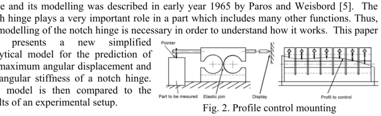
The circular notch hinge has been known for some years. It was
already used in a profile control mounting, see fig. 2 by R. Pazot [3]. This mounting is called an indicating pointer mounting and Pazot adds that this joint avoids any axis or return spring and so removes any clearance and simplifies the mounting.
Many other applications can be found in the literature as to the use of such hinges. Among other examples, Xu and King have used them in their piezoactuator displacement amplifiers [10], Ryu and al. have designed a XYθ wafer stage based on a flexure hinge [12]. The reader can find many other examples of applications in [6] and [11]. The description of the notch Fig. 1. Geometry of the
hinge and its modelling was described in early year 1965 by Paros and Weisbord [5]. The notch hinge plays a very important role in a part which includes many other functions. Thus, the modelling of the notch hinge is necessary in order to understand how it works. This paper first presents a new simplified
analytical model for the prediction of the maximum angular displacement and the angular stiffness of a notch hinge. This model is then compared to the results of an experimental setup.
ASYMPTOTIC FORMS
A first step will be to develop formulae for the case where the thickness h0 (figure 3) is very
small compared to the radius R. This gives a valuable insight to the behaviour of notch hinges.
Figure 3 presents the main geometry of the joint. The notch hinge is defined by its radius, R, minimal thickness h0, and
the thickness in the direction perpendicular to the section b. The X-axis is the axis of symmetry and the Y-axis connects the centres of the two circular arcs, ϕ is the direction angle of a particular point.
The movement of interest is the rotation about the Z-axis. We therefore basically want to determine the total deflection
angle αf of the beam under a given load, Mf. This is calculated by a classical expression of
strength of materials [4]. Only the notch hinge zone (witch extends from –R to R along the X-axis) is considered to deflect under the action of the bending moment and so, the rest of the beam is assumed to have infinite stiffness. The integral expression is similar to known integrals of lubrication theory [2] and so, Sommerfeld’s change of variables [1] is used to solve this expression. After some simple developments, the notch stiffness is found to be
5 2 0 2 9 f f M h Eb R
α = π , where E is the elastic modulus. (1)
The maximum stress in the notch is given by 0
max 2 0 6 4 3 f f M h E R bh σ α π = = . (2)
Thus, a maximum bending angle can be calculated, depending on the material and on the requested geometry 0 3 4 f R E h π σ α = . (3)
The other stiffnesses are obtained in the same manner, as fully described in [7].
For torsional stiffness (X axis), we obtain 8 05 2
9 t t M h Gb R
α = π , G being the torsion modulus. (4)
Calculation of the stretching stiffness (X axis) leads to N 1Eb h0
u =π R (5)
where N is the applied load (stretching load) and u the corresponding displacement.
The bending stiffness in the transverse direction (Y axis) is given by 1 3 0
12 ft ft M h Eb R α = π (6)
where the hinge bends through an angle αft under the load Mft along the Y-axis.
A shearing effect appears when a load is applied in the Y-axis direction. Figure 4 presents a theoretical case where shear appears, causing the translation of one side of the beam along the
Fig. 2. Profile control mounting
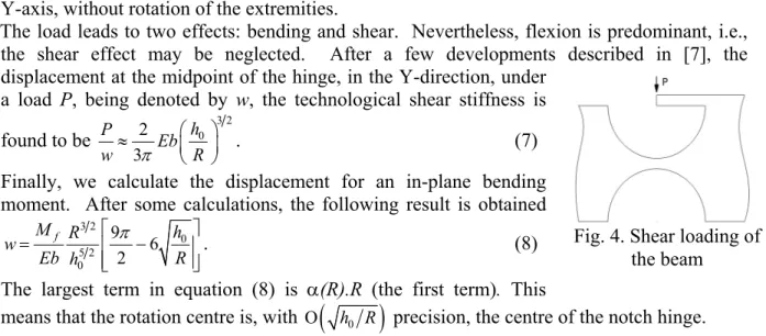
Y-axis, without rotation of the extremities.
The load leads to two effects: bending and shear. Nevertheless, flexion is predominant, i.e., the shear effect may be neglected. After a few developments described in [7], the displacement at the midpoint of the hinge, in the Y-direction, under
a load P, being denoted by w, the technological shear stiffness is found to be 3 2 0 2 3 h P Eb w π R ⎛ ⎞ ≈ ⎜ ⎟ ⎝ ⎠ . (7)
Finally, we calculate the displacement for an in-plane bending moment. After some calculations, the following result is obtained
3 2 0 5 2 0 9 6 2 f M R h w Eb h R π ⎡ ⎤ = ⎢ − ⎥ ⎢ ⎥ ⎣ ⎦. (8)
The largest term in equation (8) is α(R).R (the first term). This
means that the rotation centre is, with Ο
(
h R0)
precision, the centre of the notch hinge.CORRECTION COEFFICIENTS
The preceding results were established under the hypothesis that the ratio h0/R remains very
small. But, due to machining considerations, there is a lower bound of obtainable hinge thicknesses, so that in actual applications, higher values of h0/R may prevail, up to 0,5.
The preceding asymptotic expressions are then no longer valid. However, a system of correction factors, depending only on the ratio h0/R, has been developed by two of the authors
[7], in the following way. First, the exact values of the integrals involved in the preceding computations are developed in closed form. The correction factors are then obtained via a numerical approximation scheme.
The corrected formula for the bending stiffness is 05 2 0
1 1 2 , 1 0,137 9 f f M h h Eb R R α = Κ π Κ = + . (9)
Conversely, expression (3) must be replaced by
1 0 1 3 4 f R E h π σ α = Κ . (10)
The torsional stiffness correction factor is the same as for the bending stiffness because the same integral is involved. In the same way, a factor K2 was found for the stretching stiffness
0 0 2 2 1 , 1 0,97 h h N Eb u = Κ π R Κ = + R . (11)
The same factor K2 holds in the case of transverse bending stiffness. Formula (7) becomes 3 2 0 0 3 3 0 1 0,5 2 , 3 1 2,2 h h R P Eb w π R h R + ⎛ ⎞ = Κ ⎜ ⎟ Κ = + ⎝ ⎠ . (12)
Finally, relation (8) becomes 3 2 0
4 4 5 2 1 0 0 1 9 1 6 , 2 1 0,5 f M R h w Eb h R h R π ⎡ ⎤ = ⎢ − Κ ⎥ Κ = Κ + ⎢ ⎥ ⎣ ⎦ . (13)
The maximal error, compared to the exact solution, remains below 1,6 % for all the correction coefficients [7].
The manufacturing method influences the roughness of the surface defining the hinge. Although small, this peak to valley height (Rp) corresponds to a non-negligible decrease of the
minimal thickness, h0 (for example, if h0=0,1 mm and Rp=2,75 µm, on each face, the
difference is about 5,5%). The difference is taken in account as follows:
5 2 0 1 0 2 , 1 5 9 f p r r f M h R Eb h R α π ⎛ ⎞ = Κ Κ Κ = −⎜ ⎟ ⎝ ⎠. (14)
Fig. 4. Shear loading of the beam
EXPERIMENTAL SETUP
Stainless steel hinges with thicknesses ranging from 66 to 175 µm were manufactured using Wire Electrical Discharge Machining (WEDM). The part to be manufactured is placed in a dielectric solution and a voltage difference between a conductive part and the wire produces an electrical arc forming smelts and vaporizing the material locally. As Ryu and al. [9] have explained, WEDM is the best process to machine notch hinges without any serious impact on motion induced by machining error. The sole error is a body shape error. Tosun and al. [10] have determined a relation between the CLA roughness obtained and the two important parameters in the WEDM : the pulse duration, ti(ns), and the open circuit voltage, ui(V). The
relation is 0,048 0,3613 0,3213
( )
a i i
R = t u µm . (15)
From measurements, the ratio between Ra and Rp is found to be R Ra p =0,43. (16)
Finally, the parameters used in machining the notch hinge, ti=0,7 µs and ui=80V, lead to Rp=4,86 µm. After the WEDM machining, a shot-peening treatment is applied to the surface,
which decreases Rp to about 2,75 µm.
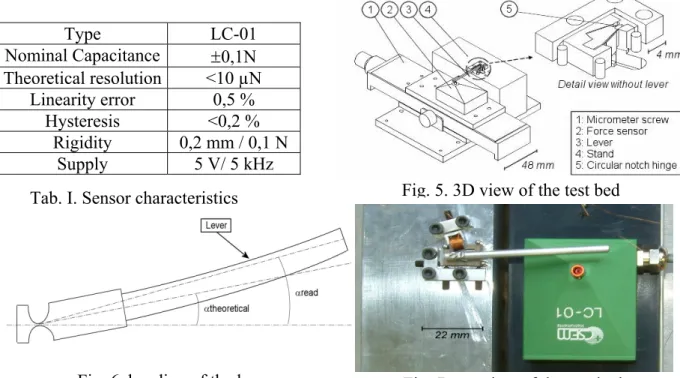
The experimental setup is depicted in figures 5 and 7. The hinge is fixed at one end. A beam (3) is fixed to the other end and the force is applied by a micrometer screw (1). A sensor (2) manufactured by CSEM is used to measure the applied force. The main characteristics of this sensor are described in table I.
Type LC-01 Nominal Capacitance ±0,1N Theoretical resolution <10 µN Linearity error 0,5 % Hysteresis <0,2 % Rigidity 0,2 mm / 0,1 N Supply 5 V/ 5 kHz
Figure 8 presents the results of the experiment conducted for one particular hinge (0,066 mm thickness). For each angular position of the hinge, three measurements of the return torque were made. The graphs present only the mean values for each position, the standard deviance being below 0,01 Nmm. This is then compared to the torque evaluated using the corrected model (9) (“model 1”).
One can easily see that the agreement between measurements and model is good for small angle displacements, smaller that 0,2°. However for large displacements, the model overestimates the experimental data. Three reasons may explain the difference.
The beam used to apply the force to the hinge may bend. The maximum deflection for a straight beam fixed at one end and free at the other is, with P the applied load, l the length of
the beam and I the area moment of inertia, Max y= −Pl3 3EI. (17)
Tab. I. Sensor characteristics
Fig. 6. bending of the lever Fig. 7. top view of the test bed
The force is not applied at the hinge axis, so this may introduce a torsional moment and thus a displacement
which can be modelled as
(
)(
1 2)
2 2 r t b d l l u l θ + + = . (18)
with θr =M Rt t , Mt =F b d
(
+)
2, d the rod diameter, Rtthe torsional stiffness of the hinge, l1 the rod length and l2
the distance between the centre of the hinge and the attachment point of the rod.
As a consequence, the displacement has three components: one resulting from deformation of the hinge (this one is interesting) , a second one from the bending of the lever and the third from the torsion of the hinge. The actual displacement is now uread = +ut uf +utheoretical. (19) The last step is now to transform this linear displacement into an angular displacement using the formula
(
)
(
1 2)
tan
a u l l
θ = + . (20)
In order to compare the measurements with the model, the measured torque must be plotted against the hinge displacement which is utheoretical = uread – ut - uf. The same
procedure can be used for angular displacements. Figure 6 shows the difference between the angular displacement measured at the end of the lever and the effective angular displacement of the hinge.
“model 2” (figure 8) considers these two modifications (bending of the lever and torsion of the hinge).
The hinge surface finish is not perfect. Roughness should be taken into account (it is not negligible compared to the thickness of the hinge). So the theoretical formula can be modified and yields a different boundary for the measurements. Returning to formula (14), another
correction coefficient has been introduced, Kr, with
Rp=2,75 µm.
In “model 3”, the complete expression of the torque (14) is considered. The results of this global method are illustrated on figure 8. The influence of the roughness is particularly interesting. The smaller the thickness of the hinge, the more important the influence of the roughness. This influence can be seen as a reduction of the thickness of the hinge thus inducing a reduction of the return torque. But it is very difficult to determine the actual value of the hinge roughness. We therefore preferred to consider the following scheme : the actual return torque lies between the modelled torque without taking into account the roughness and the torque calculated using the corrector coefficient Kr.
Figures 9 to 12 present the torque comparisons (model versus experiments) for the four different hinges that were manufactured. As explained before, to fulfil the requirements, the measurements should lie in the range defined by the model. This range is smaller for the hinge with a larger thickness. In this case, h0 has a larger value compared to Rp and so the
influence of roughness is less important. Fig. 10.
Fig. 9.
CONCLUSIONS
An asymptotic model for the prediction of the maximum angular displacement and the angular stiffness of a notch hinge has been developed. This model is valid for very
small h0/R ratios. However, due to machining
considerations, classical ratios could reach 0,5. For this value, asymptotic expressions are not valid and correction factors have been evaluated. Four hinges, manufactured using the Wire Electrical Discharge Machining (WEDM) technique, were used to validate our model. A comparison between experimental results and simulation shows good agreement for small angle deviations but not for angular deviation greater than 0,5 degrees. In addition, agreement for small thicknesses was worse than for higher thicknesses. Three reasons may explain this error: the bending of the rod used to apply the torque to the hinge, the fact that the force is not applied to the hinge axis which introduces torsion, and the hinge roughness. These three factors were modelled and taken into account to correct the model.
ACKNOWLEDGEMENTS
This work was sponsored by the Région Wallonne within the framework of the 4M-µpump project and the Belgian Programme on Interuniversity Attraction Poles initiated by the Belgian State – Prime Minister’s Office – Science Policy Program (IUAP-24).
REFERENCES
[1] A. Sommerfeld (1904)“Zur hydrodynamische Theorie des Schmiermittelreibung“, in
Zeitschrift für Math. und Physik, vol. 50.
[2] L. Leloup (1961) “Etude de la lubrification et calcul des paliers“, 2ème éd., Sciences et
Lettres, Liège.
[3] R. Pazot (1978) “Montages d’usinage. Eléments d’étude“, 4ème éd., Desforges, Paris. [4] Ch. Massonnet, S. Cescotto (1994) “Mécanique des matériaux“, 2ème éd., De Boek,
Bruxelles.
[5] J.M. Paros, L. Weisbord (nov. 1965) “How to design flexure hinges”, in Mach. Des., 151-156.
[6] Simon Henein (2001) “Conception des guidages flexibles“, Presses Polytechniques et Universitaires Romandes, Collection META.
[7] P. Merken, J.F. Debongnie (2003) “Le col circulaire comme articulation flexible“, 6ème congrès national de mécanique théorique et appliquée, Gent.
[8] J.W. Ryu, D.G. Gweon (1997) “Error analysis of a flexure hinge mechanism induced
by machining imperfection”, in Prec. Eng., vol. 21, 83-89.
[9] N. Tosun, C. Cogun, A. Inan (2003) “The effect of cutting parameters on workpiece surface roughness in wire EDM”, in Mach. Sc. & Tech., 7(2), 209-219.
[10] W. Xu, T. King (1996) “Flexures hinges for piezoactuator displacement amplifiers: flexibility, accuracy and stress considerations”, in Prec. Eng., vol. 19, 4-10.
[11] N. Lobontiu (2003) “Compliant mechanisms. Design of flexures hinges”, CRC Press.
[12] J.W. Ryu, D.G. Gweon, K.S. Moon (1997) “Optimal design of a flexure hinge based
XYθ wafer stage”, in Prec. Eng., vol. 21, 18-28. Fig. 12.