HAL Id: tel-01395481
https://pastel.archives-ouvertes.fr/tel-01395481v2
Submitted on 13 Sep 2016
HAL is a multi-disciplinary open access archive for the deposit and dissemination of sci-entific research documents, whether they are pub-lished or not. The documents may come from teaching and research institutions in France or abroad, or from public or private research centers.
L’archive ouverte pluridisciplinaire HAL, est destinée au dépôt et à la diffusion de documents scientifiques de niveau recherche, publiés ou non, émanant des établissements d’enseignement et de recherche français ou étrangers, des laboratoires publics ou privés.
titanium-composite stacks
Jinyang Xu
To cite this version:
Jinyang Xu. Numerical and experimental study of machining titanium-composite stacks. Mechanics of materials [physics.class-ph]. Ecole nationale supérieure d’arts et métiers - ENSAM, 2016. English. �NNT : 2016ENAM0022�. �tel-01395481v2�
2016-ENAM-0022
École doctorale n° 432 : Sciences des Métiers de l'Ingénieur
présentée et soutenue publiquement par
Jinyang XU
le 15 juillet 2016
Numerical and experimental study of machining
titanium-composite stacks
Doctorat ParisTech
T H È S E
pour obtenir le grade de docteur délivré par
l’École Nationale Supérieure d'Arts et Métiers
Spécialité “ Mécanique - matériaux ”
Directeur de thèse : Mohamed EL MANSORI
T
H
È
S
E
JuryM. Fabrice PIERRON, Professeur, Engineering and the Environment, University of Southampton, UK Président
M. Steven Y. LIANG, Professeur, Georgia Institute of Technology, USA Rapporteur
M. Hervé PELLETIER, Professeur, ICS - UPR 22 CNRS, INSA de Strasbourg, France Rapporteur
M. Mohamed EL MANSORI, Professeur, MSMP - EA 7350, Arts et Métiers ParisTech, France Examinateur
M. Robert PIQUET, Maître de Conférences - HDR, ICA, Université Paul Sabatier, Toulouse, France Examinateur
M. Fahad ALMASKARI, Maître de Conférences, The Petroleum Institute, Abu Dhabi, UAE Invité
Arts et Métiers ParisTech - Centre de Châlons-en-Champagne
The Ph.D. work has been finalized in the Laboratory of Mechanics, Surfaces and Materials Processing (MSMP – EA 7350) of Arts et Métiers ParisTech with the financial support of the China Scholarship Council (CSC) (Contract No. 201306230091). The study experience is a valuable and glorious journey for my life. Herein I am so fortunate to know my respected supervisor and beloved colleagues, and so lucky to receive their sincere concern and kind assistance during my three-year stay in France.
First and foremost, I would like to express my sincere gratitude to my thesis director: Prof. Mohamed EL MANSORI, for his invaluable guidance and encouragement throughout my Ph.D. research. I appreciate his responsible supervision, dedicated support, and kind assistance during my stay in France. His rigorous scholarship, keen research insight, and active academic thinking have deeply encouraged me, which will inspire me to go ahead in my future research work.
I would like to thank Prof. Fabrice PIERRON from University of Southampton, UK, for accepting to be the president of my Ph.D. defense committee as well as for his insightful comments and constructive advice on my thesis. I am very grateful to Prof. Steven Y. LIANG from Georgia Institute of Technology, USA, and Prof. Hervé PELLETIER from INSA de Strasbourg, France, for accepting to be the referees and for spending their precious time and great efforts in reviewing my thesis. I am also honored to be able to invite Prof. Robert PIQUET from Université Paul Sabatier, France, and Dr. Fahad ALMASKARI from The Petroleum Institute, Abu Dhabi, UAE, to attend my Ph.D. defense, and I sincerely appreciate their valuable comments on my thesis.
I gratefully acknowledge the financial support of the China Scholarship Council (CSC), which enables me to finalize my Ph.D. study in Arts et Métiers ParisTech, France.
I would like to acknowledge and extend my appreciation to all the technicians and staffs in the MSMP laboratory of Arts et Métiers ParisTech, especially Mr. Julien VOISIN, Mr. Claude SCHMITT, Dr. Lotfi HEDJAZI, Dr. Laurence FOUILLAND-PAILLÉ and Dr. Anne HUGUET who have provided me much technical assistance throughout my Ph.D. work. Besides, I am grateful to Prof. Halim HADDADI and Dr. Sabeur MEZGHANI for providing me many helpful suggestions and constructive comments on both my research work and future job plan. Furthermore, my cordial and sincere thanks also go to all the labmates in the MSMP and my friends in France including Mohammed YOUSFI, Simon JOLIVET, Faissal CHEGDANI, Kévin SERPIN, Imane OUTMANI, Fan LI, Qing XIA, and Peng WANG with whom I have shared an enjoyable and wonderful time in France.
Last but not least, I would like to give the most heartfelt thanks to my parents for their selfless support, deep love, and endless encouragement. Their meticulous care and excellent support are the key sources of my continuous endeavor, progress, and growth in both study and life. Herein I sincerely wish them successful work, good health, and good luck.
Jinyang Xu
ABSTRACT
In modern aerospace industry, the use of hybrid CFRP/Ti stacks has experienced an increasing trend because of their enhanced mechanical/physical properties and flexible structural functions. The key advantages of delivering energy saving and improving system function have awarded the bi-material a promising alternative for substituting individual composite and metal applications in various industrial fields. However, due to their anisotropic mechanical behaviors and poor machinability, machining hybrid CFRP/Ti stacks in one shot time still remains the main scientific and technological challenge in modern manufacturing sectors. Particular issues may arise from the high force/temperature generation, poor surface quality, and rapid tool wear. On the current research advancement, the existing scientific work dealing with hybrid CFRP/Ti stack cutting was still performed solely via the experimental methodology, which is cost-prohibitive and time-consuming.
Compared to the previous investigations in literature, the present work aims to provide a combined numerical and experimental study on cutting comprehension of hybrid CFRP/Ti stacks. To this aim, an original FE model comprising three fundamental physical constituents was established to construct the anisotropic machinability of the bi-material system. The CFRP phase was modeled as an equivalent homogeneous material (EHM) by implementing the Hashin damage criteria to simulate the rupture and separation of the fiber/matrix system. The Ti phase was assumed isotropic with elastoplastic behavior, and Johnson-Cook criteria were utilized to replicate the local failure of the metallic phase. The CFRP/Ti interface physically described as an intermediate constituent was modeled through the concept of cohesive zone (CZ). The numerical work aims to provide preliminary inspections of the key cutting mechanisms dominating the hybrid CFRP/Ti machining in order to facilitate the post-experimental studies.
Afterward, some systematic experimental work including orthogonal cutting, combined CFRP/Ti machining, and hole drilling was carefully performed versus different input cutting conditions. The key responses of hybrid CFRP/Ti stack machining including chip separation process, machined surface quality, tool wear mechanism were precisely addressed via both numerical and experimental methodologies. Special foci were made on the inspections of different cutting sequences’ influences on hybrid CFRP/Ti stack machining and induced bi-material interface damage formation. The combined numerical-experimental studies provide the key findings aiming to (i) reveal the activated mechanisms controlling the interface cutting and subsequent interface damage formation, (ii) clarify the influences of different cutting-sequence strategies (CFRP → Ti
Ti → CFRP) on hybrid CFRP/Ti stack machining, (iii) outline the machinability classification
of hybrid CFRP/Ti stacks, and (iv) analyze the parametric effects and tool geometry/material influences on cutting of hybrid CFRP/Ti stacks.
I
Contents
Chapter I ... 1
1.1 Introduction ... 4
1.2 Material properties and characterization ... 5
1.2.1 FRP composite phase ... 5
1.2.2 Titanium alloy phase ... 6
1.2.3 FRP/Ti stacked assembly ... 7
1.3 Drilling force characterization ... 10
1.4 Cutting mechanisms controlling FRP/Ti drilling ... 13
1.4.1 FRP-phase drilling: brittle fracture dominant mechanisms ... 14
1.4.2 Interface drilling: interrelated and mixed cutting mechanisms ... 15
1.4.3 Ti-phase drilling: plastic-deformation dominant mechanisms ... 17
1.5 Drilling-induced damage... 17
1.5.1 Hole damage produced in FRP phase ... 18
1.5.2 Interface damage: the weakest interfacial region ... 21
1.5.3 Hole damage produced in Ti phase ... 22
1.6 Tool wear mechanisms in FRP/Ti drilling ... 25
1.7 Strategies for high-quality drilling ... 29
1.7.1 Cutting parameters ... 30 1.7.2 Cutting tool ... 31 1.7.3 Cutting environment ... 35 1.8 Numerical approaches ... 36 1.8.1 FRP composite modeling ... 36 1.8.2 Ti alloy modeling ... 40 1.9 Concluding remarks ... 43
Chapter II ... 45
2.1 Introduction ... 472.2 Physical behavior and basic configuration of hybrid CFRP/Ti stacks ... 47
2.2.1 Ti alloy phase ... 48
2.2.1.1 Microstructure and composition of Ti6Al4V alloy ... 48
2.2.2 CFRP laminate phase ... 50
2.2.2.1 Mechanical property and behavior of CFRP laminate ... 50
2.2.2.2 Machining behavior of CFRP laminates ... 52
2.3 Geometrical features and boundary conditions of the hybrid composite model ... 53
2.3.1 Adopted assumptions for numerical simulations ... 53
2.3.2 FE model for interface cutting and interface damage formation investigation ... 53
2.3.3 FE model for cutting sequence and frictional response studies ... 56
2.3.4 Equations of motion: Abaqus/Explicit scheme ... 57
2.4 Material constitutive law and progressive damage criterion ... 58
2.4.1 Ti-phase constitutive model ... 59
2.4.2 CFRP-phase model ... 61
2.4.3 Interface constitutive model ... 65
2.5 Experimental validation of the OC model ... 68
2.6 Conclusions ... 71
Chapter III ... 73
3.1 Introduction ... 75
3.2 Workpiece configuration and properties ... 75
3.3 Cutting tool details ... 78
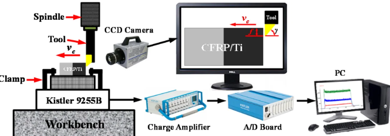
3.4 Measuring systems and experimental techniques ... 82
3.4.1 On-site measuring system ... 83
3.4.1.1 Force generation characterization ... 83
3.4.1.2 Chip separation process monitoring ... 84
3.4.2 Post-treatment analyses ... 84
3.4.2.1 Optical microscope and microhardness analysis ... 84
3.4.2.2 Surface roughness and 3D profiling ... 85
3.4.2.3 Hole dimensional feature measurement ... 88
3.4.2.4 SEM and EDS techniques ... 88
3.5 Experimental setup and cutting design ... 89
3.5.1 Orthogonal cutting and combined CFRP/Ti machining setup ... 89
3.5.2 Experimental setup for hole drilling ... 91
3.6 Conclusions ... 92
Chapter IV ... 95
4.1 Introduction ... 97
4.2.1 Cutting process investigation ... 98
4.2.2 Mechanisms of interface damage formation ... 100
4.2.3 Subsurface damage study ... 107
4.3 Evaluation of different cutting-sequence strategies ... 109
4.3.1 Comparison of chip formation process ... 110
4.3.2 Assessment of machined surface morphology ... 113
4.3.3 Evaluation of induced subsurface damage ... 115
4.4 Parametric effects on hybrid CFRP/Ti stack machining ... 116
4.4.1 Cutting process inspection ... 116
4.4.2 Machined surface quality inspection... 119
4.4.3 Parametric study on CFRP/Ti cutting responses... 122
4.5 Frictional responses dominating CFRP/Ti cutting process ... 124
4.5.1 Frictional effects on specific cutting energy ... 125
4.5.2 Frictional effects on machined surface quality ... 129
4.5.3 Frictional effects on induced damage and surface integrity ... 130
4.6 Conclusions ... 134
Chapter V ... 137
5.1 Introduction ... 139
5.2 Chip removal process ... 139
5.3 Cutting process and force signal analysis ... 145
5.4 Parametric effects on force generation ... 147
5.5 Machined surface quality inspection... 151
5.6 Surface roughness and microhardness ... 157
5.7 Tool performance and wear mode investigation ... 160
5.8 Conclusions ... 164
Chapter VI ... 167
6.1 Introduction ... 169
6.2 Drilling process and force signal characterization ... 170
6.3 Drilling force magnitudes and specific drilling energy ... 175
6.4 Analysis of chip type in drilling ... 180
6.5 Hole quality analysis ... 181
6.5.1 Surface roughness ... 182
6.5.2 Hole diameter and roundness error ... 184
6.6.1 Hole edge morphology ... 187
6.6.2 Delamination damage analysis ... 189
6.6.3 Burr defect analysis ... 191
6.7 Hole wall topography and surface morphology ... 193
6.7.1 Hole wall topography ... 193
6.7.2 SEM analysis of drilled hole surface ... 196
6.8 Drill design implications ... 198
6.9 Conclusions ... 199
Chapter VII ... 203
7.1 Key conclusions ... 204
7.2 Future perspectives ... 206
Annexe A : Résumé de thèse ... 209
Appendix B: Publication list and scientific presentation ... 227
1
Chapter I
Literature review: the state-of-the-art
advances in hybrid FRP/Ti stack
Nomenclature
a Dimensional constant
Adel Delamination area
Anom Nominal area of the drilled hole
b Dimensional constant
CTFI Critical thrust force for metal → FRP
CTFII Critical thrust force for FRP → metal
BCC High-temperature β phase
D Drill diameter
D11 Coefficients for the bending stiffness of FRP laminate
D12 Coefficients for the bending stiffness of FRP laminate
D22 Coefficients for the bending stiffness of FRP laminate
D66 Coefficients for the bending stiffness of FRP laminate
Dc Equivalent bending stiffness coefficient of FRP laminate
Dmax Maximum diameter of the delamination area
Dnom Nominal hole diameter
DRAT Two-dimensional delamination factor
E Elastic modulus
f Feed rate
Fd One-dimensional delamination factor
Fda Adjusted delamination factor
FRP → Ti Drilling strategy from FRP phase to Ti phase
FRP → Ti
Ti → FRP Drilling from FRP → Ti and/or Ti → FRP
GIC Critical energy release rate in fracture mode I
h Dimensional constant
HCP Low-temperature α phase
n Spindle speed
Pch Concentrated force
q Uniformly distributed force
Ra Arithmetic mean roughness
Rt Peak to valley height
Rz Ten point mean roughness
T Material thickness
Ti → CFRP Drilling strategy from Ti phase to CFRP phase
tm Multi-tool-work interaction time
vc Cutting speed
WC/Co Tungsten carbide
α Used weight in Fda
αr Rake angle
β Used weight in Fda
v Poisson’s ratio
ϕ Drill point angle
ψ Drill helix angle
λ Thermal conductivity
ξ Proportional coefficient
Abbreviation
Al Aluminum ALE Arbitrary Lagrangian Eulerian
BCJ Baummann-Chiesa-Johnson
BUE Built-up edge
CTF Critical thrust force
CVD Chemical Vapor Deposition
doc Depth of cut
EHM Equivalent homogeneous material
FEM Finite element method
FRP Fiber reinforced polymer
HSS High-speed steel
JC Johnson-Cook MQL Minimum quantity lubrication
MTS Mechanical Threshold Stress
PCD Polycrystalline diamond
PVD Physical Vapor Deposition
TEC Thermal expansion coefficients Ti Titanium
1.1 Introduction
In modern aerospace industry, the manufacturing sectors are seeking the use of hybrid composite stacks to enhance the characteristics of new-generation structures and continuously motivate the development of mechanical assemblies favoring the energy saving [1]. Material made of multi-phases of fiber reinforced polymer (FRP) and aluminum (Al) or titanium alloy (Ti) is a typical example of hybrid composite stack configuration. The benefits of the composite-to-metal alliance arise from the ability to combine resistance and to enhance specific characteristics without significantly increasing the part weight [2]. The key advantages of delivering energy saving and improving system performance have made the material a viable candidate to override standard composites and single metal alloys in various industrial applications [3, 4]. Aircraft structures subjected to high thermo-mechanical stresses are successfully fabricated with these materials. The typical application is the use of the wing-fuselage connection of the Boeing 787 Dreamliner.
Among the available configurations of hybrid composite stacks, FRP/Ti configuration (FRP/Ti, FRP/Ti/FRP, Ti/FRP/Ti), is identified as a most popular one due to its best combination of metallurgical and physical properties including high strength-to-weight ratio, low density, excellent corrosion/erosion resistance [5-7]. In particular, the FRP/Ti stack exhibits a high strength-to-weight ratio with yield strength as high as 830 MPa and a density of roughly 4 g/cm3 [8]. Moreover, the FRP/Ti coupling yields also many advantages over the FRP/Al coupling in several aspects such as reduced galvanic corrosion, improved specific strength, etc. [9, 10]. Such superior properties have made their key application focus on manufacturing the key load-bearing components of large commercial aircraft in modern aerospace industry.
With regard to its assembly, the stacked FRP and Ti phases are usually joined by mechanical fastening technique, which is the principal method currently used for aerospace structural assembly with the advantage of good reliability, easy detachability and convenient inspectability [11-14]. Since the assembly process demands a large number of holes, the good control of machining becomes extremely crucial for achieving undamaged parts. In addition, the FRP and Ti phases are often stacked together prior to being cut off in one-shot time. This minimizes the positional errors and favors tight tolerances in actual production.
Although machining FRP/Ti stack in one one-shot time is beneficial from a manufacturing standpoint [2, 8, 15, 16], the processing task still remains extremely challenging because of the large disparity in properties of involved phases. For instance, the FRP laminate shows anisotropic behavior [17, 18] and abrasive nature [19] consisting of two distinct constituents (reinforcing fiber and polymer matrix) with neatly different properties. The reinforcing fiber exhibits elastic brittle behavior and poor thermal conductivity, while the polymer matrix shows ductile behavior. As for the Ti alloy, it exhibits poor thermal conductivity, low elastic modulus, and high chemical reactivity to most used tool materials [20-22]. These characteristics typically lead to severe abrasive tool wear and tool edge chipping especially against the FRP phase [23-26]. Besides, the tool experiences serious Ti adhesion, intense flank wear and premature tool failure in Ti machining[27, 28].
Technically, the key challenges involved in hybrid FRP/Ti machining may arise from the poor conditions of the multi-tool-work interactions associated with the disparate natures of the stacked constituents. The non-compliance between the tool-metal interface, on one hand, and the tool-composite interface, on another hand, induces local interface discontinuities and, hence, affects
the cutting behavior. These discontinuities present the major obstacles to be overcome for better controlling of the cutting conditions and proper selection of the tool-work configuration, which consists of the main scientific and technological challenge. To cope with the key challenge encountered in industry, great efforts have been made in the past few decades aiming to improve the machinability of the hybrid composite stack by considering various input factors including cutting parameter, cutting tool and cutting environment. In such circumstance, pointing out a state-of-the-art advances concerning hybrid FRP/Ti machining can provide a beneficial guide for both current and future research.
This Chapter is thus dedicated to making a rigorous literature survey of the most significant achievements gained in hybrid FRP/Ti machining. The multiple aspects related to hybrid composite stack cutting have been carefully addressed based on analyses of the open literature. Several strategies and approaches devoted to high-quality machining of hybrid FRP/Ti stacks are also precisely investigated. Moreover, the numerical approaches for potential solution to hybrid FRP/Ti machining are also finally reviewed.
1.2 Material properties and characterization
1.2.1 FRP composite phase
Advanced composite laminates, such as fiber reinforced polymer (FRP) laminates have been broadly employed in structural components due to their attractive properties including high specific stiffness, high strength and high corrosion resistance. The main family of FRP laminates commonly used in industries includes CFRP (carbon fiber reinforced polymer) laminates [29], GFRP (glass fiber reinforced polymer) laminates [30], and fiber metal laminates (FMLs) [31]. Among them, the CFRP and GFRP laminates are by far the most-used constituents in a hybrid composite stack configuration in view of their high mechanical properties. The primary constituents in the FRP phase are reinforcing fibers (e.g., carbon and glass) and polymer matrices (e.g., thermoplastic resin and thermosetting resin). The fibers are characterized by lightweight, stiff and strong nature, which contributes to enhanced mechanical and tribological properties of the material system, while the polymer matrix binds the fibers together, providing load transfer and structural integrity. The mechanical properties of FRP laminates critically depend upon the fiber layup along the epoxy matrix. For example, the unidirectional fiber-orientation prepreg ply (UD-ply) shown in Fig.1.1(a)
[32, 33]exhibits quite-different mechanical properties along/in perpendicular to the fiber direction,
i.e., maximum stiffness/strength along the fiber direction and minimum properties in perpendicular
to the fiber direction. However, a bidirectional fiber-orientation prepreg ply (woven-ply) presented
in Fig. 1.1(b) [32, 33] almost has the maximum stiffness/strength along the both directions. For
multi-orientation FRP laminates, they are usually made by bonding many prepreg plies together at different fiber orientations (cross-ply) to gain enhanced properties. Fig.1.1(c) shows the scheme of one type multi-orientation FRP laminate following the quasi-isotropic stacking sequence of [0°/45°/90°/-45°]6s[33, 34].
The FRP laminate globally exhibits heterogeneous characteristic, anisotropic nature, and brittle behavior, which inevitably results in extremely poor machinability. Structural components made of FRP laminates are mostly manufactured in near-net-shape to gain accurate dimensional tolerance and ensure excellent assembly performance, especially in a hybrid stack configuration. The
disparate natures of the fiber-epoxy system as well as their inherent heterogeneity make the machining operation more difficult than conventional metal cutting. Drilling FRP laminate in a hybrid stack configuration exhibits a more challenging task than standard composite drilling case due to the interrelated coupling with the metal-phase cutting and serious damage in the composite-metal interface. Relevant discussion will be presented in the following subsections of this Chapter.
Figure 1.1. Scheme of the commonly-used FRP composite structures: (a) UD-ply laminate [32, 33], (b) woven-ply
laminate [32, 33], and (c) multi-orientation laminate following quasi-isotropic stacking sequence of [0°/45°/90°/-45°]6s
[33, 34]. 1.2.2 Titanium alloy phase
Titanium alloys used in a hybrid stack configuration aim at providing high strength-to-weight ratio, high hot hardness, excellent corrosion resistance and good fatigue properties of the assembly. The superior properties of titanium phase mainly have a close relation with the presence of its metallurgical characteristics in the matrix. In the viewpoint of crystalline state, the titanium exists in two different phases referring to a low-temperature α phase (HCP) and a high-temperature β phase (BCC). The HCP structure of titanium affords a limited number of slip or shear planes while the BCC structure has more slip systems, thereby enabling more deformation locally transformed from HCP into BCC. Pure titanium typically undergoes an allotropic transformation probably at 882°C, changing from the low-temperature close-packed hexagonal α phase to the higher-temperature body-centered cubic β phase [6]. The allotropic transformation temperature is very sensitive to some certain added elements. For instance, the α stabilizers such as Al, O, N, Ga, and C elements produce an increase in the temperature while the β stabilizers such as Mo, V, Cu, Cr, Fe, Mn, Ni, ect., produce a decrease of the transformation temperature [35]. In contrast, some other neutral elements like Sn, Si, and Zr have gentle influences on the transformation temperature.
Typically, the Ti alloys can be categorized into four main groups according to its basic metallurgical characteristics: (i) commercially pure alloy, (ii) α and near α alloy, (iii) α - β alloy, and (iv) β alloy [6, 35].
Commercially pure (unalloyed) titanium: exhibits excellent corrosion resistance and low strength properties.
α and near α alloys: contain α stabilizers and exhibit excellent creep resistance.
α - β alloys: comprise both α stabilizers and β stabilizers. The α - β alloys are generally
structural alloys and are widely used in structures and engine components in the aerospace industry. Among them, Ti6Al4V is the most well-known one comprising about 45 % to 60 % of the total titanium production.
β alloys: include significant quantities of β stabilizers. This type of alloys often shows high
hardenability and high density.
With respect to its machinability, the titanium alloy is usually regarded as a difficult-to-cut material in current manufacturing industries, which is attributed to its inherent high strength maintained at elevated temperature and low thermal conductivity leading to high cutting temperature generation. The Ti chips are usually formed in the “serrated” nature as a result of various cycles of compression and adiabatic plastic shear phases in the chip formation process, causing high fluctuations of cutting force acting over a small tool-chip contact area (probably 1/3 of that in the case of steel) [36, 37]. Moreover, the titanium alloy also exhibits high chemical reactivity to most-used tool materials at high elevated cutting temperature. In titanium alloy drilling, special issues may arise from the high force/temperature generation, rapid tool wear and poor surface integrity. For drilling Ti phase in a hybrid composite stack configuration, the Ti drilling action obtains significant coupled influences from the composite-phase drilling making the cutting mechanisms more complicated than single Ti alloy drilling cases. Relevant discussion will be presented in the following subsections of the Chapter.
1.2.3 FRP/Ti stacked assembly
The emergence of hybrid FRP/Ti stack aims to overcome the individual limitations of each constituent involved and to obtain enhanced structural functions. The typical configurations of FRP/Ti stacks are CFRP/Ti6Al4V and GFRP/Ti6Al4V that are widely used in modern aerospace industry. The bi-material system usually offers enhanced superior properties of each stacked phase including high strength-weight ratio, higher specific strength, high corrosion resistance, etc., which makes them an ideal substitute for single composite or metal application and leads to an increasing demand in modern aircraft manufacturing.
Drilling is indeed one of the most important and fundamental machining operations prior to the applications of the hybrid FRP/Ti stack. However, due to the varying properties and poor machinability of the stacked constituents, drilling FRP/Ti stack with acceptable hole quality remains the most difficult and challenging task in modern manufacturing sectors. Severe hole damage, excessive interface consumption as well as rapid tool wear are the key problems encountered in drilling. Exploring the drilling behavior and improving the machinability of the FRP/Ti stacks play a crucial role in high efficiency-precision machining of the material. To this aim, great motivations have been exploited in order to address deeply the topics, and a large amount of scientific work has been undertaken within the past few decades. Table 1.1 summarizes the experimental studies that have been conducted in the open literature concerning FRP/Ti drilling topics [2, 3, 8, 15, 38-51].
Table 1.1
Experimental researches concerning hybrid FRP/Ti drilling in the open literature [2, 3, 8, 15, 38-51].
Reference Stack configuration Drill type Cutting conditions Key topics addressed
Ramulu et al. [2] FRP (Gr/Bi)/Ti6Al4V
FRP: IM-6 graphite bismaleimide composite θ = [45°/90°/-45°/0°/-45° /0°/45°/0°/-45°/90°/-45° /0°/45°/0°/45°/90°/-45° /90°/90°]s T = 7.62/3.1 mm HSS, HSS-Co, carbide twist drills
n = 325, 660, 1115, 1750, 2750 rpm f = 0.03, 0.08, 0.13, 0.20, 0.25 mm/rev Drilling forces, Hole production, Tool wear, Hole damage, Surface topography Brinksmeier and Janssen [15] AlCuMg2/CFRP/Ti6Al4V θ = [45°/90°/0°/45°]s T = 10/10/10 mm Uncoated twist drill, Step drills (uncoated, TiB2, diamond) D = 16 mm, ϕ = 130° ψ = 30° vc = 10, 20 m/min f = 0.15 mm
Cutting environment: dry and oil mist conditions
Workpiece quality, Tool wear
Park et al. [8] CFRP/Ti6Al4V CFRP: quasi-isotropic graphite/epoxy laminate T = 7.54/6.73 mm WC twist drills D = 9.525 mm ϕ = 135° ψ = 28° n = 2000, 6000 rpm (CFRP) n = 800, 400 rpm (Ti) f = 0.0762 (CFRP), 0.0508 mm/rev (Ti)
Cutting environment: dry and wet
Drilling forces, Tool wear, Hole quality
Park et al. [45] CFRP/Ti6Al4V
CFRP: multidirectional graphite epoxy composites T = 7.54/6.73 mm WC, PCD drills D = 9.525 mm ϕ = 135° ψ = 28° n = 2000, 6000 rpm (CFRP); 300, 400, 800 rpm (Ti) f = 0.0762 mm/rev (CFRP); 0.0508 mm/rev (Ti) Cutting environment: mist
Drilling forces, Tool wear Isbilir and Ghassemieh [42] CFRP/Ti6Al4V CFRP: T700-M21CFRP θ = [90°/-45°/0°/45°]5s T = 20/20 mm TiAlN-coated drills D = 8mm ϕ = 140° ψ = 45° n = 1400 rpm (Ti) and 4500 rpm (CFRP) f = 119 mm/min (CFRP) and 457 mm/min (Ti) Drilling forces, Delamination, Burrs, Surface roughness, Tool wear Kim and Ramulu [43] FRP (Gr/Bi)/Ti6Al4V FRP: IM-6 graphite bismaleimide composite θ = [45°/90°/-45°/0°/-45° /0°/45°/0°/-45°/90°/-45° /0°/45°/0°45°/90°/-45° //90°/90°]s T = 7.62/3.1 mm HSS-Co, split-Point, carbide drills n = 660, 1115, 1750 rpm f = 0.08, 0.13, 0.20, 0.25 mm/rev Drilling process optimization, Hole quality, tool wear
Brinksmeier et al. [3] AlCuMg2/CFRP/Ti6Al4V CFRP: multiphase of unidirectional prepregs T = 10/10/10 mm
Twist drill, step drill
D = 16mm
vc = 40 m/min
vf = 5 mm/min
Cutting environment: minimum quantity lubrication (MQL) Thermal and mechanical loads, Surface microstructure and damage Shyha et al. [49] Ti6Al4V/CFRP/Al-7050
θ = [45°/0°/135°/90°/45° /0°]s T = 10/10/10 mm Uncoated, CVD diamond-coated, C7-coated drills D = 6.35mm ϕ = 130° ψ = 30° 20 m/min ≤ vc ≤ 120 m/min f = 0.05,0.10,0.15 mm/rev
Cutting environment: wet, spray mist condition
Hole size, Hole surface roughness,
Hole edge quality, Microhardness of metal, Chip formation Ghassemieh [41] CFRP/Ti6Al4V CFRP: M21E CFRP C7-coated carbide drills D = 6mm n = 1400 and 4500 rpm f = 119 and 457 mm/min Drilling forces, Tool wear, Surface roughness Beal et al. [38] CFRP/Ti6Al4V
CFRP: quasi-isotropic graphite/epoxy laminate T = 7.54/6.73 mm WC drills D = 9.525mm ϕ = 135° ψ = 28° n = 400, 800 rpm (Ti) n = 2000, 6000 rpm (CFRP) f = 0.0508 mm/rev (Ti) and
0.0762 mm/rev (CFRP)
Cutting environment: wet lubrication condition
Drilling forces, Tool wear, Hole quality, Surface roughness
Park et al. [46] CFRP/Ti6Al4V CFRP: quasi-isotropic graphite/epoxy laminate T = 7.54/6.73 mm WC, BAM-coated drills n = 2000, 6000 rpm (CFRP); 400, 800 rpm (Ti) f = 0.051 mm/rev Tool wear, Tool performance Fujiwara et al. [40] CFRP/Ti6Al4V CFRP: composed of 1 ply GFRP and 10 ply CFRP T = 3/9.5 mm and 3/10.5 mm
TiAlN, TiSiN and TiAlCr/TiSi-coated drills
D = 6 mm
vc = 18.8 m/min
f = 0.2 mm/rev
Cutting environment: dry and mist-water cooling Drilling forces, Tool wear, Hole quality Tashiro et al. [50] CFRP/Ti6Al4V CFRP: composed of 1 ply GFRP and 10 ply CFRP T = 3/9.5 mm TiAlN, TiAlCr/TiSi coated drills D = 6mm vc = 9.4, 18.8 m/min f = 0.1, 0.2 mm/rev
Cutting environment: dry and water-mist-cooling Cutting forces, Tool wear, Hole quality, Cutting environment comparison SenthilKumar et al. [48]
CFRP/Ti6Al4V Solid WC twist
drills (with different tool point angles) ϕ = 130° ψ = 30° n = 612 and 1826 rpm f = 0.05 mm/rev Tool wear, Chip formation, Effects of drill point angle on tool wear
Poutord et al. [47] CFRP/Ti6Al4V T = 20.7/25.5 mm K20 uncoated drill D = 12mm n = 2652 rpm (CFRP); 265 rpm (Ti) Drilling forces, Tool wear
ϕ = 140° ψ = 30°
f = 0.05 mm/rev (CFRP); 0.2
mm/rev (Ti) Kuo et al. [44] Ti6Al4V/CFRP/Al-7050
θ = [45°/0°/135°/90°/45° /0°]3s T = 10/10/10 mm DLC diamond drill, CVD diamond drill D = 6.38 mm ϕ = 140° ψ = 30° vc = 30 m/min (Ti); vc = 120 m/min (CFRP, Al) f = 0.08, 0.15 mm/rev Thrust force, Torque, Tool wear, Hole accuracy, Burr formation Carvajal et al. [39] CFRP/Ti; CFRP/Al; CFRP/CFRP
Not specified Variable cutting conditions including drilling machine, nature of materials, feed rate, spindle speed, etc.
Effects of different input factors on hole diameter
Wang et al. [51] CFRP/Ti6Al4V, Ti6Al4V, CFRP θ = [(0°/45°/90°/-45°)4 (0°/90°/0°/90°)]s T = 7.54/6.73 mm Uncoated, AlTiN, nanocomposite coated drills D = 9.525 mm ϕ = 135° ψ = 25° n = 6000 rpm, f = 0.0762 mm/rev (CFRP, CFRP/Ti); n = 500 rpm, f = 0.0508 mm/rev (Ti, CFRP/Ti) Drilling forces, Tool wear mechanisms in CFRP-only, Ti-only and CFRP/Ti drilling
1.3 Drilling force characterization
Force generation represents the key cutting physics in FRP/Ti drilling, which indicates the mechanical energy consumption of multi-tool-work interactions governing the chip removal process. The force generation primarily has a close relation with the inherent properties of each stacked constituent as well as their disparate modes of chip formation. From the aspect of force analysis, the force generation induced in drilling is commonly decomposed into two components, i.e., thrust force and the torque, which signify the tribological behaviors between tool-chip interaction and tool-machined surface interaction, respectively. Severe force fluctuations in both thrust and torque components are often encountered when drilling hybrid FRP/Ti stacks. The force-magnitude discrepancy mainly arises from the fiber orientation’s effects on the FRP-phase drilling, the variable chip separation mode in interface drilling and the serrated chip formation in Ti-phase drilling. The changeable chip formation modes occurring on tool rake face would be the key factor significantly affecting the torque-force component in the stack drilling. The thrust force component, however, signifies the interactions between tool flank face and the machined hole wall surface. In addition, the disparate properties arising from the composite-metal phases also cause the drilling-force signal to exhibit certain stage characteristics. Fig.1.2 shows the thrust force and torque signals varied with cutting depth when drilling FRP (Gr/Bi)/Ti stack by using standard HSS drill under the fixed cutting conditions of n = 660 rpm and f = 0.2 mm/rev [2]. It is observed that three major regions referring to the FRP, interface and Ti drilling zones in thrust and torque profiles are noticeable. Furthermore, the entire hybrid FRP/Ti drilling action can also be distinguished by seven minor regions.
Region 1 defines the period when the chisel edge firstly penetrates into the FRP phase. Both thrust and torque force components increase gradually from zero.
Region 2 implies that the cutting lips are gradually involved in the FRP-phase drilling. The cutting-force signals increase gradually with tool advancement.
Region 3 entails the period of full engagement of the drill lips through the FRP-phase. The thrust force and torque nearly keep constant in this region drilling.
Region 4 denotes the period of drill bit involved in the FRP/Ti interface drilling. The tool-work interaction transfers from the absolute tool-FRP interaction, gradually to multi-tool-work interaction and finally to absolute tool-Ti interaction, resulting in the significant increase of the drilling forces.
Region 5 indicates that the cutting lips have gradually cut into the Ti phase and continuous force elevation has been obtained. The maximum thrust force is achieved at the end of this region drilling.
Region 6 represents that the cutting lips have totally cut into the Ti phase.
Region 7 signifies the period that the chisel edges have gradually penetrated out of the Ti phase. The thrust force component is found to decrease gradually to zero. However, torque component above zero is expected at the end of the process due to tool friction, depending on the elastic springback effect of the composite material.
Figure 1.2. Drilling-force versus cutting depth when drilling hybrid FRP (Gr/Bi)/Ti stacks by using standard HSS
drill. (Material: Gr/Bi FRP/Ti6Al4V, θ = [45°/90°/-45°/0°/-45°/0°/45°/0°/-45°/90°/-45°/0°/45°/0°/45°/90°/-45°/90°/90°]s,
cutting parameters: n = 660 rpm and f = 0.2 mm/rev) [2].
Moreover, the force generation in FRP/Ti drilling exhibits strong sensitivity to the input variables. Special variables commonly addressed are drilling parameters (spindle speed and feed rate), drilled hole number (tool wear), etc. Ramulu et al. [2] studied the influence of drilling parameters on the force generation when drilling FRP (Gr/Bi)/Ti stacks, as depicted in Fig. 1.3. Results showed that the feed rate played a pivotal role in affecting the thrust force magnitudes for both HSS and carbide drills. Generally, a slight increase of feed rate often gave rise to a significant elevation of the thrust force, irrespective of the tool material. This is because higher feed rate typically signifies larger
uncut chip thickness to be removed and denotes more cutting energy to be consumed, i.e., the drill bit is required to cut off more chip volume per revolution and overcome much higher cutting resistance. As a result, the thrust force was elevated dramatically. In contrast, the relation between spindle speed and thrust force was inconspicuous. In addition, the spindle speed was observed to have minor effects on the thrust force generation in all regions except region 7 when using HSS and carbide drills as depicted in Fig. 1.3(b) and Fig. 1.3(d). Furthermore, in other literature [41, 42], the spindle speed was confirmed to exhibit positive effects on the drilling forces (thrust and torque components) for FRP-phase drilling while have negative effects on the drilling forces (thrust and torque components) for Ti-phase drilling. The phenomenon can be attributed to the hardening and softening effects of increased high temperature on the work materials caused by the elevated spindle speed, respectively.
Figure 1.3. Thrust force versus feed rate and spindle speed when drilling hybrid FRP/Ti stacks: (a) n = 660 rpm - HSS
drill, (b) f = 0.0732 mm/rev - HSS drill, (c) n = 660 rpm - carbide drill, (d) f = 0.0732 mm/rev - carbide drill work. (Material: Gr/Bi FRP/Ti6Al4V, θ = [45°/90°/-45°/0°/-45°/0°/45°/0°/-45°/90°/-45°/0°/45°/0°/
45°/90°/-45°/90°/90°]s, T = 7.62/3.1 mm)[2].
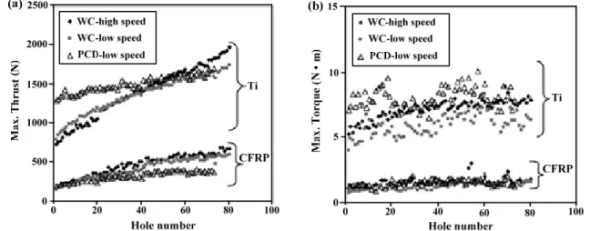
In most open literature, drilled hole number (tool wear) was identified as another key factor significantly influencing the drilling force generation. Fig.1.4 shows the experimental results gained
by Park et al. [45] when drilling CFRP/Ti6Al4V with WC and PCD drills. It is apparent that the
thrust force and torque produced in CFRP-phase and Ti-phase drilling are linearly proportional to the drilled hole number, irrespective of the used tool materials. The phenomenon can be explained by the fact that when a large number of holes have been drilled, the tool will suffer excessive and expanded tool wear. As a result, the tool undergoes high tool-work friction coefficient when drilling further uncut chip material, resulting in high cutting energy consumption and subsequent high-force
generation. The identical findings were also confirmed by Beal et al. [38], Fujiwara et al. [40],
Tashiro et al. [50] and Wang et al. [51].
Figure 1.4. Effects of drilled hole number on (a) thrust force and (b) torque when drilling hybrid FRP/Ti stacks by
using WC and PCD drills. (Material: multidirectional graphite epoxy composites/Ti6Al4V, T = 7.54/6.73 mm; cutting tools: WC and PCD with ϕ = 135°, ψ = 28°; cutting parameters: WC - high speed: n (CFRP) = 6000 rpm, n (Ti) = 800 rpm; WC-low speed: n (CFRP) = 2000 rpm, n (Ti) = 400rpm; PCD-low speed: n (CFRP) = 2000 rpm, n (Ti) = 300 rpm;
f (CFRP) = 0.0762 mm/rev, n (Ti) = 0.0508 mm/rev; cutting environment: mist coolant) [45].
1.4 Cutting mechanisms controlling FRP/Ti drilling
Drilling hybrid FRP/Ti stacks exhibits behavior quite different from drilling standard composites and single metal alloys due to the multi-tool-work interaction domains. The disparate natures of each constituent make the chip formation modes more coupled and interrelated governing the bi-material machining. The interrelated mechanism dominating the material removal process plays a pivotal role in affecting the machining responses and physical phenomena. Revealing the mechanisms controlling FRP/Ti drilling can provide a beneficial guide for cutting-parameter optimization, hole-quality control and tool selection.
Figure 1. 5. Schematization of the FRP → Ti cutting sequence used
in vertical drilling of hybrid FRP/Ti stacks[10, 45].
In FRP/Ti drilling, two different cutting-sequence strategies referring to Ti → FRP and FRP →
Ti commonly exist from the aspect of tool-entry and tool-exit throughout the material removal process. The reasonable cutting sequence would rest the FRP material on top of the Ti alloy and cut from the FRP phase first especially from the viewpoint of vertical drilling configuration as illustrated schematically in Fig. 1.5 [10, 45]. This is because in this cutting sequence the Ti alloy can act the role of supporting plate in preventing laminate deflection and limiting the workpiece dynamics during the drilling operation. Therefore, it can result in the low extent delamination damage and improved tool life. The beneficial role of FRP → Ti sequence was also proven by several relevant work [2, 42, 45]. Fig.1.6 presents a comparison of the exit CFRP surface damage generated in drilling single CFRP laminate without Ti phase and in drilling CFRP/Ti stacks [42]. It was apparent that the CFRP → Ti drilling sequence promoted less fiber pullout (probably near-net shape) than the single CFRP drilling case. Therefore, based on the proposed drilling sequence (FRP → Ti), the FRP/Ti drilling mechanisms are then discussed from FRP-phase drilling, to interface drilling and finally to Ti-phase drilling, respectively.
Figure 1.6. CFRP surface damage at the exit side after drilling the 1st hole:
(a) drilling of standard CFRP laminates after making the 1st hole and (b) drilling of hybrid CFRP/Ti stacks (CFRP → Ti cutting sequence). (Material: CFRP (T700-M21, θ = [90°/-45°/0°/45°]5s, T = 20 mm) / Ti6Al4V(T = 20 mm); cutting
tool: AlTiN twist drill; cutting parameters: n = 4500 rpm, f = 457 mm/min)[42]. 1.4.1 FRP-phase drilling: brittle fracture dominant mechanisms
In FRP-phase drilling, the cutting mechanisms differ significantly from conventional metal cutting cases due to the brittleness and heterogeneity of the fiber/matrix system. The mechanisms governing the FRP-phase drilling should be responsible for the specific chip formation mode and chip type.
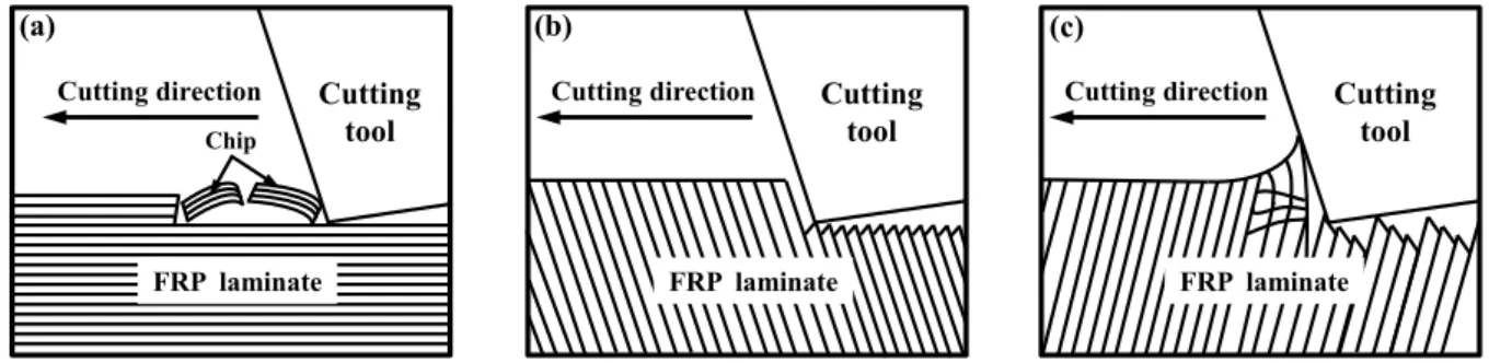
Figure 1.7. Schematization of the chip formation mechanisms in FRP laminate cutting: (a) layered peeling fracture, (b)
extrusion shear fracture, and (c) bending shear fracture[52].
When drilling FRP phase, material removal occurs through a series of successive ruptures aided by diverse nature and uneven load shearing between matrix and fibers. Such chip formation is motivated by brittle fracture due to crack initiation and propagation in the primary shear zone after
Cutting tool Cutting direction (b) FRP laminate Cutting tool Cutting direction Chip FRP laminate (a) Cutting tool Cutting direction (c) FRP laminate
the chip is partly formed as shown in Fig. 1.7 [52]. Since brittle fracture operates as the dominant cutting mode controlling the material removal process, the resected “discontinuous” chips are often produced in the form of “powdery” dust. However, the chip type produced in drilling greatly depends on the properties and fiber volume fraction of fiber/matrix system. In some cases, the “continuous” chip formation as like metal cutting can also be generated. The experimental findings obtained by Hocheng and Puw [53] indicated that when drilling carbon/epoxy the main chip-type were absolutely “discontinues” form but for carbon/acrylonitrile butadiene styrene (ABS) drilling, the predominant chip type would be “continuous” one. The activated mechanisms controlling the chip characteristics could be expalined by the fact that the material removal of the former was governed by brittle fracture while the latter was ruled by predominant plastic deformation due to the ABS’s capacity of large elongation under cutting loads. In addition, when increasing fiber volume fraction, the majority of the composite materials are removed by a series of fracture due to the non-uniform plastic deformation that promotes the formation of “discontinuous” chip type. Moreover, the chip type is also influenced by input cutting parameters like feed rate. Results gained
by Kim et al. [54] showed that when low-feed drilling (f = 0.02 mm/rev) of PEEK thermoplastic
composites, the resected chips were typically “continuous” and curling for a wide range of speeds due to high overall toughness of the thermoplastic matrix. In contrast, when higher feed rate was employed (f = 0.25 mm/rev), the generated chips were basically “discontinuous”. However, the key mechanism dominating the feed-rate effects on the chip-type transition from “continuous” to “discontinuous” was not clarified in the authors’ research. Anyway, the mechanisms controlling the chip separation can be identified as the key contributor to the produced chip type. The chip-separation mechanism dominating the FRP-phase drilling, however, is critically dependent on tool rake angle (γ), i.e., the angle between fiber orientation (θ) and cutting direction. However, these factors are not reviewed here individually, since the key objective of this Chapter is to survey the mechanism issues on hybrid composite stack drilling. Readers are recommanded to refer to the mentioned literature [55-63]. It should be stressed here that in drilling, the changeable fiber breaking type versus θ, on one hand, is a key contributor to severe hole-wall damage like delamination, fiber pullout, micro cracking, matrix degradation, etc. On the other hand, it makes the distribution of some local defects like fiber pullout, delamination, spalling, etc., exhibit regional symmetrical characteristic. These findings were also confirmed by some pertinent research work
[17, 61, 64, 65].
1.4.2 Interface drilling: interrelated and mixed cutting mechanisms
In FRP/Ti drilling, the bi-material interface machining commonly involves multiple aspects of mechanical/physical consumptions and experiences mixed cutting behaviors governing the material removal process. The drilling mechanisms dominating the interface cutting are generally the interaction of both composite-leading mode and metal-leading mode. The interrelated chip separation modes make the region more vulnerable to various damage formation and defect generation.
As the drill bit penetrates into the FRP/Ti interface (as shown in Fig. 1.8), discontinuous tool-work interactions consisting of tool-FRP coupling and tool-Ti coupling take place and dominate the tool active cutting zones, causing the tool to be involved in a multi-tool-work
interaction machining. Cutting mechanism governing this region drilling comprises multiple aspects of physical and mechanical phenomena in the cutting zones and mixed cutting behaviors in the material removal process. The non-compliance among the tool-work interfaces inevitably gives rise to a particular harsh cutting condition and more interrelated cutting behavior dominating the drilling operation. The cutting edge segments as depicted in Fig. 1.8 will then experience a mixed material removal process of fiber fracture and metal elastic-plastic deformation simultaneously throughout the multi-tool-work interaction time.
Figure 1.8. Schematization of the drill bit involved in the FRP/Ti interface drilling.
The multi-tool-work interaction time (tm) governing the interface drilling, as illustrated in Fig.1.8,
is critically dependent on the used drill diameter (D), drill point angle (ϕ), spindle speed (n) and feed rate (f), and can be expressed as follows.
cot 2 2 m D t nf (1.1)
During the interface drilling period, the main cutting edges, on one hand, undergo discontinuous and disparate thermal effects and mechanical loads from the multiple tool-work interfaces, which may result in significant weakening of tool material and serious tool blunting. On the other hand, they experience an interface transition during the material removal process, i.e., transforming from absolute tool-FRP interaction to multi-tool-work interaction and finally to absolute tool-Ti interaction. As a result, the cutter will suffer intense force fluctuation and load vibration, and hence will result in the instability of the tool-work system during the stack drilling. These phenomena can be identified as a main trigger to the hole damage formation concerning the FRP/Ti interface. In addition, since the tool-FRP coupling and tool-Ti coupling exhibit disparate tribological behaviors, the drill in such condition will suffer mixed wear patterns during the interface cutting. The combined wear modes will significantly accelerate the tool wear and greatly shorten the tool life.
To alleviate the detrimental effects arising from interface drilling, reducing the multi-tool-work interaction time would be a direct solution. As shown in Eq.(1.1), it can be inferred in theory that reducing drill diameter (D) as well as increasing point angle (ϕ), spindle speed (n) or feed rate (f) can lead to the reduction of interface cutting time, and hence can promote desirable drilling results. In general, the interface drilling can be regarded as the most difficult cutting stage as compared to the FRP-phase drilling and Ti-phase drilling. However, to the authors’ best knowledge, the underlying physical/mechanical behavior governing the multi-interaction area drilling and also the
1 2 1 2D m L n f t
parametric effects on interface drilling are still not well understood. Relevant in-depth researches focused on the issues are rarely found. The lack of experimental studies on the aforementioned issues can be attributed to the challenge and difficulty in inspecting the multiple and sophisticated tool-work interactions in actual drilling cases. In the future, special attempts should be made to address deeply the issues.
1.4.3 Ti-phase drilling: plastic-deformation dominant mechanisms
When the drill edges thoroughly cut into the Ti phase, the multi-tool-work interaction coupling governing the cutting zones is absolutely transformed into the tool-Ti interaction. The metal elastic-plastic deformation then dominates the Ti-tool interaction area. The shearing actions from the thermal-mechanical coupling effects generate “continuous” chips that flow on the tool rake face. Under such fixed cutting condition, the drilling process is assumed to reach a steady state for which the cutting force, drilling temperature, and surface integrity could be predicted to an acceptable accuracy. However, since the Ti phase has poor thermal conductivity and strong chemical affinity to used tool materials, the drilling action may cause serious hole damage and catastrophic tool failure
[27, 45]. On one hand, the smaller contact area between tool-chip interfaces in Ti alloy drilling
often results in stress concentration at the tool edge where the maximum cutting stresses are reached. In addition, the poor thermal conductivity of Ti alloy often results in inefficient heat dissipation and causes intense heat accumulation on tool substrate, which will lead to the severe thermal damage of the tool cutting surface. On the other hand, the hot and continuous chips produced in Ti drilling also considerably impair the FRP hole and deteriorate the hole quality during their evacuation from the bottom layer.
The unfavorable chip transportation always causes catastrophic abrasion and erosion as well as high hole-diameter tolerance in the FRP phase. Such results observed by Brinksmeier and Janssen [15] showed that the scratching effect of Ti chips on the CFRP hole could cause a high-depth erosion of approximately 300 μm by using conventional twist drill in multi-phase AlCuMg2/CFRP/Ti6Al4V stack drilling. To alleviate the chip-evacuation effects, some researchers
[2, 43] asserted that it was not suggested to employ cutting parameters consisting of low spindle
speed and low feed rate in hybrid composite stack drilling since these parameters favored the formation of “continuous” Ti chips, which would result in a large extent of subsurface damage in the polymeric holes.
Therefore, considering the distinct cutting mechanisms for each phase drilling, it is recommended to make a compromise selection in tool geometry and cutting parameters that often lead to high drilling forces, poor hole quality and severe tool wear in hybrid composite stack drilling [43, 66, 67]. Since the Ti phase usually causes the biggest problems, it has been reported that the process parameter selection in drilling FRP/Ti stacks should match that of the more difficult-to-drill workpiece Ti alloy rather than that of the easier-to-drill material FRP [68].
1.5 Drilling-induced damage
Drilling-induced damage is often characterized by the extent of geometric defects, thermal injuries and physical damage. Since the hybrid composite stack comprises both FRP and Ti phases, the machined holes always have not only the unique defects of composite material (e.g., matrix
cratering, delamination, fiber pullout, thermal alteration) but also the hole imperfections of metallic alloy (e.g., hole size error, roundness error, position error, burrs). The composite-metallic damage usually results in the poor assembly tolerance and long-term performance deterioration of the machined structural components [69]. A list of the commonly addressed drilling damage in FRP/Ti cutting is summarized in Table 1.2. Fig. 1.9 [16, 43] shows the schematic diagram of the drilling-induced hole damage distribution in FRP/Ti stack.
Table 1.2
Commonly induced hole damage types when drilling hybrid FRP/Ti stacks.
Phase type Drilling-induced damage
FRP phase Matrix cratering, delamination, fuzzing, micro crack, fiber/matrix debonding, spalling, fiber pullout, fiber breaking, resin loss, surface cavities, thermal alteration, etc.
FRP/Ti interface Discoloration ring, damage ring, delamination, etc.
Ti phase Hole size error, roundness error, position error, surface drag, burr, cracking, feed marks, tearing surface, debris of microchips, surface plucking, deformed grains, surface cavities, etc.
Figure 1.9. Schematization of the hole damage distribution in hybrid FRP/Ti stack drilling [16, 43].
1.5.1 Hole damage produced in FRP phase
In FRP phase drilling, damage formation commonly occurs through a series process of fiber fracture, matrix cracking and inter-laminar debonding, etc. Owing to the heterogeneity and anisotropy of the fiber/matrix system, severe hole damage is often promoted in drilling. Generally, the drilling-induced damage of FRP phase can be classified into four categories: geometric defects, temperature-related damage, delamination at drill-entry and drill-exit [70]. The tool geometry related damage is associated to the angle between fiber direction and the cutting edge. The temperature-induced damage including micro crack, resin loss, and matrix degradation is commonly produced by the thermal effects of drilling heat on the hole wall surface. In contrast, the damage due to delamination is usually a matter of greatest concern as it affects surface finish and work strength significantly leading to a large number of part rejections. The delamination depends on not
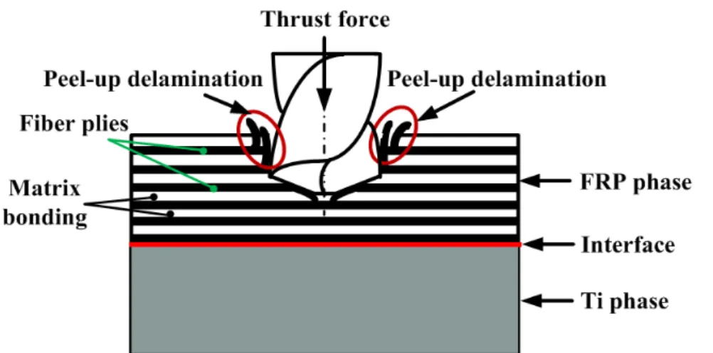
only fiber/matrix natures but also their adjacent properties [71, 72]. It should be stressed that in single FRP drilling, two mechanisms responsible for delamination may take place at the entry and exit of the drilled hole periphery, which are well-known as “peel-up delamination” and “push-out delamination”, respectively. However, in FRP/Ti stack drilling, especially under FRP → Ti drilling sequence, the peel-up delamination may become a dominant one while the push-out delamination is less likely to happen due to the beneficial effect of bottom-supporting Ti phase on preventing the deflection and deformation of the upper composite phase. Qi et al. [73] further revealed that the bottom-supporting metal thickness also has significant effects on the push-out delamination formation, especially when the metal thickness exceeds a so-called critical value (a specified thickness threshold for the free-delamination occurrence), no push-out delamination takes place. For peel-up delamination, as the drill bit cuts into the FRP phase, the cutting edges of the drill abrade the laminate. In such case, a concentrated peeling force will be formed through the slope of the drill flutes and then will separate the plies from the uncut portions beneath the tool forming a delamination zone around the hole entry periphery, as illustrated in Fig. 1.10.
Figure 1.10. Scheme of the peel-up delamination in drilling hybrid FRP/Ti stacks (FRP → Ti cutting sequence).
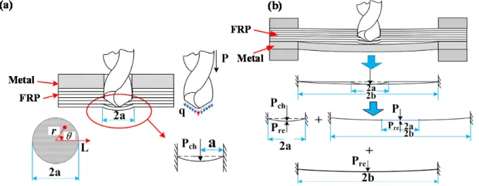
Since the delamination belongs to an irreparable damage and an inter-ply failure, it is recognized as a most critical factor that severely impairs the performance of the machined components and accounts for probably 60 % of the part rejections in the aerospace industry [33, 53, 70, 74-76]. In general, it is believed by many researchers [73, 77-79]that there exists a critical thrust force (CTF) in composite drilling or composite/metal drilling, below which no delamination takes place. And for detailed information about CTF readers are recommended to refer to the aforementioned literature. In order to predict the CTF in FRP/metal stack drilling, Qi et al. [73] established the analytical models based on linear elastic fracture mechanics, classical bending plate theory and the classical lamination theory. In their models, the CTF (P) responsible for the push-out delamination was simplified and modeled as a resultant force of a concentrated one (Pch) at the chisel edge and a
uniformly distributed one q at the cutting lips, which could be expressed as Pch = ξ × P, where ξ
represented a proportional coefficient varied in the range of 50 % - 70 % depending on the tool geometrical parameter and the cutting variables [80]. Both CTF models in two drilling sequences,
i.e., drilling from FRP → metal and drilling from metal → FRP, were discussed in their research,
which are illustrated in Fig. 1.11and summarized in Table 1.3, respectively. The results showed that the CTF obtained from the theoretical models yielded an acceptable agreement with the
experimental measurements. When drilling from FRP → metal, the CTF yielded a higher value than that operated in metal → FRP drilling sequence, which indicated that the FRP → metal drilling sequence would be more beneficial for free-delamination drilling of hybrid FRP/metal stack than its counterpart one. Furthermore, the authors also pointed out that when the metal thickness exceeded the critical thickness, no delamination damage would take place in the case of FRP → metal drilling sequence, regardless of the process parameters. However, the established models were restrained to solely predicting the CTF of conventional twist drill in drilling hybrid FRP/metal composite and ignored some internal factors like the effects of composite layup and plate shape on push-out delamination.
Figure 1.11. Delamination analysis for different cutting-sequence strategies applied in hybrid FRP/metal drilling: (a)
metal → FRP cutting sequence and (b) FRP → metal cutting sequence [73].
Table 1.3
Analytical models for predicting CTF under different cutting-sequence strategies when drilling hybrid FRP/metal composite [73].
Drilling sequence Scheme of delamination Analytical model of critical thrust force (CTF)
Metal → FRP cutting sequence Fig.1.11(a)
11 12 22 66
2 3 3 2 3 4 I I IC CTF P G D D D D 11 12 22 66 1 3 2 3 4 3 c D D D D D FRP → metal cutting sequence Fig.1.11(b)
11 12 22 66
2 3 3 2 3 4 II II IC CTF P G D D D D K
2 2 2 2 2 2 2 2 2 2 3 2 ln 2 ln 9 1 2 c c a a b a a b D D K a a b a b a b Eh b D Note: CTFI, CTFII – critical thrust forces for metal → FRP and FRP → metal drilling, respectively; GIC - the
critical energy release rate in mode I; ξ-proportional coefficient; D11, D12, D22, D66 - coefficients stand for the
bending stiffness of the uncut FRP laminate; Dc - the equivalent bending stiffness coefficient of the FRP laminate; v
In addition, the delamination visualization and assessment in hybrid FRP/Ti drilling also remain a difficult and challenging task because of its internal and external nature. At present, the most used non-destruction methods for characterizing the size, shape, and location of delamination are optical microscopy, ultrasonic C-Scan and X-ray computerized tomography [75, 78, 79, 81-85]. In addition, the extent of the delamination damage is often evaluated by using one-dimensional delamination factor (Fd) [17, 23, 79], two-dimensional delamination factor (DRAT or DF) [24, 86, 87] or adjusted
delamination factor (Fda) [88] as listed in Table 1.4. The main differences among the three criteria
rely on fact that the one-dimensional delamination factor represents the simplest way to measure the extent of delamination damage in actual production while the two-dimensional and adjusted delamination factors can accurately assess the real extent of delamination damage since they minimize the influences of a few fibers peeled up or pushed down on the delamination measurement.
Table 1.4
Delamination factors used for damage evaluation when drilling FRP laminates [17, 23, 24, 79, 86-88].
Type of delamination factor Equation expression Remarks Authors
One-dimensional Fd d max nom D F D
Dmax -maximum diameter
of the delamination area;
Dnom - nominal diameter
of the drilled hole
Xu et al. [17], Chen [23], Tsao and Hocheng [79]
Two-dimensional DRAT or DF del RAT nom A D A 100% del nom F nom A A D A
Adel - delamination area; Anom - nominal area of the
drilled hole
Faraz et al. [24], Davim and Reis [86], Mehta et al.
[87]
Adjusted Fda da max del
nom nom
D A
F
D A
α, β - the used weights in
Fda Davim et al. [88]
1.5.2 Interface damage: the weakest interfacial region
In FRP/Ti drilling, the interface linking the composite phase and metal phase boundaries would be the weakest region vulnerable to severe damage formation due to the particular harsh and varying cutting conditions governing the cutting zones as discussed in subsection 1.4.2. Since the FRP phase and Ti phase exhibit disparate mechanical/physical properties, it induces local interface discontinuities and non-compliance among the tool-work interfaces, which significantly affects the tool cutting behavior. When the cutting tool reaches the interface region, the tool tips and cutting
edges suffer severe shocks and vibrations due to the changeable chip separation modes from tool-FRP interaction to tool-Ti interaction and vice versa. Such physical phenomenon makes the drilling operation much easier to promote damage formation. Generally, the interface damage was reported in the form of discoloration ring, damage ring, fiber pullout and delamination as shown in
Fig.1.12 [2].The mentioned interface damage was often irreparable and fatal, which would promote
crack initiation and fatigue fracture during the stack’s assembly process.
Figure 1.12. (a) Damage region at the composite/Ti interface, (b) the top view of the damage region, and (c) the side
view of the damage region of (b). (Material: Gr/Bi FRP/Ti6Al4V, θ = [45°/90°/-45°/0°/-45°/0°/45°/0° 45°/90°/-45°/0°/45°/0°/45°/90°/-45°/90°/90°]s, T = 7.62/3.1 mm; (a): cutting tool: HSS, HSS-Co and carbide drills,
cutting parameters: n = 1750 rpm, f = 0.08 mm/rev; (b) and (c): cutting tool: HSS-Co drill, cutting parameters: n = 2720 rpm, f = 0.08 mm/rev) [2].
Concerning the interface damage formation, several scholars [2, 8] have revealed that the cutting heat and chip evacuation are the pivotal factors contributing to the damage initiation and propagation. Specific reason can be attributed to the unique physical properties of the Ti phase. Since the Ti alloy is characterized by poor thermal conductivity (λs ≈ 7-7.9 W·m−1°C−1), the cutting
heat generation in the interface cannot be dissipated effectively, which, in turn, induces a local heat concentration at the bi-material interface. The accumulated cutting heat will cause thermal softening and degradation of the FRP/Ti interface. Besides, the produced continuous Ti chips also result in severe scratches and intense abrasions on the bi-material interface, leading to the force-induced delamination. In addition, Ramulu et al. [2] pointed out that the drilled hole number (tool wear) and feed rate also influenced the interface damage. For instance, when lower feed rate was used, larger interface damage was generated due to the longer tool-work engagement resulting in more Ti heat generation accumulated on the interface region. However, apart from the feed rate and tool wear, in fact, tool geometries like drill diameter and point angle (as illustrated in subsection 1.4.2) also have crucial effects on the generated interface damage, while their effects were not studied by the authors. Moreover, the explicit theories to explain the interface damage formation and the in-depth studies on quantitatively correlating the interface damage and input parameters are still significantly lacked.
1.5.3 Hole damage produced in Ti phase
When the tool edges attack the Ti phase, the previous brittle fracture changes into elastic-plastic shearing, and thus the generated surface quality tends to be improved a bit as compared to the FRP phase drilling. However, the most significant problem in hybrid composite drilling always occurs in the metal phase due to the poor thermal conductivity of the Ti alloy that leads to the localized heat generation concentrated at the tool-chip interface. The thermal congestion inevitably results in high cutting temperature governing the tool active zones, exacerbating the interface damage, burr defect, heat-induced delamination and surface roughness. The key forms of the surface defects as reported
![Figure 1.1. Scheme of the commonly-used FRP composite structures: (a) UD-ply laminate [32, 33] , (b) woven-ply](https://thumb-eu.123doks.com/thumbv2/123doknet/2961105.81452/19.892.182.707.278.612/figure-scheme-commonly-used-composite-structures-laminate-woven.webp)
![Figure 1.15. Cutting performance of different tool materials used in hybrid FRP/Ti stack drilling [111]](https://thumb-eu.123doks.com/thumbv2/123doknet/2961105.81452/45.892.185.712.686.992/figure-cutting-performance-different-materials-hybrid-stack-drilling.webp)

![Figure 2.8. Typical uniaxial strain-stress response of ductile material failure process [172]](https://thumb-eu.123doks.com/thumbv2/123doknet/2961105.81452/73.892.197.693.560.853/figure-typical-uniaxial-response-ductile-material-failure-process.webp)
![Figure 2.11. Scheme of the mechanical responses of the cohesive zone under different fracture modes [187] : (a) fracture mode II and mode III, (b) fracture mode I.](https://thumb-eu.123doks.com/thumbv2/123doknet/2961105.81452/80.892.124.776.299.566/scheme-mechanical-responses-cohesive-different-fracture-fracture-fracture.webp)