O
pen
A
rchive
T
OULOUSE
A
rchive
O
uverte (
OATAO
)
OATAO is an open access repository that collects the work of Toulouse researchers and makes it freely available over the web where possible.
This is an author-deposited version published in : http://oatao.univ-toulouse.fr/ Eprints ID : 12160
To link to this article : DOI:10.4028/www.scientific.net/AST.91.117 URL : http://dx.doi.org/10.4028/www.scientific.net/AST.91.117
To cite this version :
Etcheparre, Pierre-Luc and Vergnes, Hugues and Samélor, Diane and Sadowski, Daniel and Brasme, Caroline and Caussat, Brigitte and Vahlas, Constantin Amorphous alumina coatings on glass
bottles using direct liquid injection MOCVD for packaging
applications. (2014) Advances in Science and Technology, vol. 91 .
pp. 117-122. ISSN 1662-0356
Any correspondance concerning this service should be sent to the repository administrator: [email protected]
Amorphous alumina coatings on glass bottles using direct liquid
injection MOCVD for packaging applications
P.-L. Etchepare
1, a *, H. Vergnes
2,b, D. Samélor
1,c, D. Sadowski
1,dC. Brasme
3,e, B. Caussat
2,f, C. Vahlas
1,g1
Centre Interuniversitaire de Recherche et d’Ingénierie des Matériaux (CIRIMAT) ENSIACET, 4 Allée Emile Monso, BP 44362, 31432 Toulouse Cedex 4, France
2
Laboratoire de Génie Chimique (LGC)
ENSIACET, 4 Allée Emile Monso, BP 84234, 31432 Toulouse Cedex 4, France
3
SGD, Avenue Pierre et Marie Curie, 80350 Mers-les-Bains, France
a
[email protected], b [email protected], c [email protected],
d
[email protected], e [email protected], f [email protected],
g
Keywords: MOCVD, direct liquid injection, amorphous alumina, aluminum tri-isopropoxide, complex geometry, process modeling, hydrolytic resistance.
Abstract. In the field of packaging, coatings are commonly applied on containers to avoid
interactions between them and their content. For glass bottles, application of a thin film prevents interactions with the phase in contact and consequently the alteration of surface properties of the latter. In this article, we propose an innovative way to apply amorphous alumina coatings on glass bottles by metalorganic chemical vapor deposition from aluminum tri-isopropoxide. A numerical model, using the Computational Fluid Dynamics code FLUENT, has been developed to calculate local profiles of gas flow, temperature, concentration and deposition rates into the reactor. The sub-micrometric alumina films have been deposited at reduced pressure between 480°C and 670°C. Uniform thickness profiles have been determined on cross sections over the length of the bottle and have been successfully simulated. Strongly improved hydrolytic resistance with regard to the uncoated bottles reveals the excellent performance of the films.
Introduction
Aluminum oxide is a promising material with an increasing technological and industrial interest regarding its numerous properties for a wide panel of applications: refractive index and optical transmittance for the optical field [1], insulating properties for microelectronic components [2, 3], chemical inertness and high hot-hardness for wear resistance [4], catalyst support [5], protection against corrosion [6, 7]. Alumina thin films also provide enhanced barrier properties [8-10]. Different techniques exist to form alumina coatings on metal or polymer substrates such as electron beam evaporation [2], magnetron sputtering [3], atomic layer deposition [9], sol-gel [6] or metal-organic chemical vapor deposition (MOCVD) [1]. Among them, MOCVD is one of the most attractive for the preparation of such coatings on complex-in-shape geometries with conformal coverage i.e. uniform thickness along the surface and controlled nature and structure of the material. Alumina MOCVD requires the decomposition of a precursor, such as aluminum tri-isopropoxide (ATI) [6, 11-15], aluminum tri-sec-butoxide [1] or aluminum dimethyl-isopropoxide [4]. ATI is able to produce amorphous and stoichiometric alumina coatings with a smooth and dense microstructure in the temperature range 450°C to 700°C [11-14]. Deposition of thin films inside cavities or near-closed geometry has only been scarcely investigated [10]. The objective of this study is to apply alumina coating on an almost closed geometry substrate such as a glass bottle, to understand the phenomena occurring during the elaborated MOCVD process by implementing a numerical model, and to test the barrier properties of the film. In that which follows, the MOCVD reactor and processing conditions will be exposed in parallel with the design and assumptions of the process modeling. Results of local profiles of gas velocity and precursor concentration will be
presented, followed by experimental and calculated thickness profiles. Coating morphologies and performances will be investigated using Scanning Electron Microscopy (SEM) and hydrolytic resistance respectively.
Experimental
The classical MOCVD of ATI requires conditioning the liquid compound inside a bubbler and vaporizing it with N2 flow. However, with this technique it is difficult to get constant vapor
pressure of the precursor. Taking in account the low activation energy for this process in the entire temperature range of interest [14] which results in mass transport limited operation, it is tedious to establish a robust and reproducible process. Direct liquid injection (DLI) allows overcoming the previously mentioned drawbacks [16, 17]. However, the implementation of a DLI technology in a CVD process involving ATI requires its dissolution in a solvent to allow its injection, vaporization and transport to the deposition area. Cyclohexane (C6H12) was selected as a convenient solvent of
ATI.
ATI is sensitive to humidity and is subjected to ageing upon exposure to ambient atmosphere [11]. Water vapor undergoes partial and total hydrolysis of the ATI molecule Al(OiPr)3
in a few volatile compounds Al(OiPr)3-n(OH)n (n = 1, 2) and Al(OH)3 respectively [11, 18]. ATI
(98% pure, Acros Organics CAS N° 555-31-7) was used as received. It was stored in a glove box and manipulated under dry argon atmosphere: It was sealed into a glass ampoule inside the glove box and then cyclohexane (99.5% extra dry, Acros Organics CAS N° 110-82-7) was injected with a syringe using Schlenk technique under argon flow.
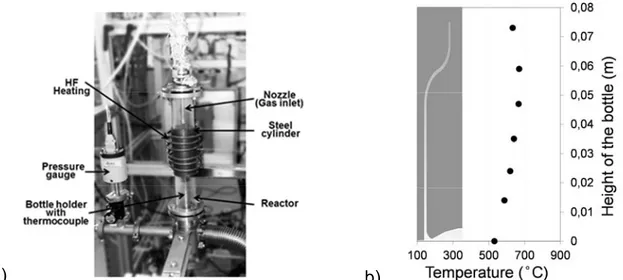
Depositions were performed in a vertical hot-wall reactor, composed of a quartz tube and an inductively heated, external coaxial stainless steel (SS) tube for thermoregulation. Figure 1a presents a photograph of the MOCVD setup. The glass bottle to be coated was positioned on a metallic support. Temperature was monitored by a thermocouple grazing its external bottom surface on the central axis of the bottle. All experiments were performed at 480°C at that point, corresponding to an experimentally determined temperature profile at the internal walls of the bottle shown in Figure 1b. The DLI of the solution is carried out with a Kesmtream Vapbox 500® instrument.
a) b)
Fig. 1 : (a) Photograph of the MOCVD reactor for deposition of alumina coating inside glass bottles – (b) Temperature profile on the internal wall (sketched) of the bottle
The reactive gas phase was introduced from the upper part of the reactor through a SS nozzle. It was composed of the vaporized solution and of dilution gas. 99.9992% pure N2 (Air
Products) was used and was fed through lines equipped with MKS mass flow rate controllers. The total flow rate (dilution N2, cyclohexane, ATI) was maintained unchanged at 585 standard cubic
centimeters per minute (sccm) for all experiments. The liquid flow rate was 0.7 g/min corresponding to an inlet ATI molar fraction of 1.7 10-3. The regulated total pressure was set at 666 Pa. At the reactor outlet, products of the reactions were trapped upstream to the pump. Deposition experiments duration was 30 min. After treatment, the coated bottles were fractured following their height. Film thickness and surface morphology along the internal surface of each bottle was measured on cross sections by SEM performed on a LEO 435VP instrument.
Coatings performance was determined by the hydrolytic stability, which is the resistance to the release of soluble mineral substances from the inner surface of the container in contact with water. The measurement conditions come from the European pharmacopoeia taken as reference [20]. Glass bottles were carefully cleaned and then filled with distilled water. They were placed into an autoclave and heated during 1 h at 121°C. The hydrolytic resistance was measured by titrating released alkali with 0,01M hydrochloric acid.
Process modeling
A numerical model using the ANSYS suit and the Computational Fluid Dynamics (CFD) code FLUENT 12.1 was used to simulate the deposition of alumina from ATI into the glass bottle. An axisymmetric, 2D configuration was considered, composed of 100,620 cells. The mesh was refined in regions close to the bottle surface and in those with high gradients in particular at the aperture of the bottle, using the velocity gradient as indicator. Grid independence of the results was verified. Conservation equations of mass, momentum, energy and gas species concentration including kinetics of alumina deposition were solved to calculate local profiles of gas flow, temperature, mass fraction and deposition rate inside the reactor. Steady-state, laminar conditions and compressibility effects were considered. Heat of reaction was not taken into account due to the low ATI molar concentration. Properties of the gaseous species and the multicomponent diffusion coefficients were calculated using the kinetic theory. Lennard-Jones parameters for N2 and H2O
were taken from the FLUENT database whereas those for C6H12 and C3H6 were found in the
literature [19]. These parameters were unknown for ATI and taken from the molecule of n-decane which has almost the same number of carbon atoms. The following apparent chemical reaction was used to describe the deposition of alumina from ATI [14]:
[Al(OC3H7)3]4 → 2 Al2O3 + 12 C3H6 + 6 H2O (1)
The corresponding apparent heterogeneous kinetic law is:
Rsi = k0*exp(-Ea/RT)*[ATI]n (kg/(m2s)) (2)
where k0 is a pre-exponential constant, Ea (J/mol) an activation energy, T (K) the temperature,
[ATI] the ATI concentration and n the apparent reaction order. The kinetic parameters have been taken from Vergnes et al. [18] as k0 = 5.81 107 kg.m2.5/(mol1.5s), Ea = 78.1 kJ/mol and n = 1.5.
The inlet ATI and C6H12 mass fractions were taken equal to those provided by the DLI
system at the upper section of the nozzle inlet. On the walls, a classical no-slip condition was used for gas velocity and the mass flux density of each species was assumed to be equal to the corresponding heterogeneous reaction rate. The experimentally measured thermal profile was fixed as thermal boundary conditions on the bottle walls.
Results and Discussion
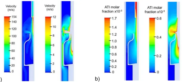
Figure 2 presents calculated local profiles in large and fine scales of gas velocity (Fig. 2a, 2b) and of ATI molar fraction (Fig. 2c, 2d). Gas flow presents a parabolic profile inside the nozzle and near to the bottle inlet, characteristic of laminar flow. The gas velocity at the entrance of the
bottle reaches 97 m/s, and 12 m/s at half-height on the central axis which reveals the existence of high convective transfer rates. These values correspond to a residence time inside the bottle shorter than 100 ms. Moreover, a high velocity (50 m/s) can be observed close to the inlet walls of the bottle contrary to lateral and bottom walls. So, complex combinations of convective and diffusive phenomena exist in the bottle during deposition. ATI is rapidly consumed at the inlet of the bottle. The ATI molar fractions at the bottle inlet decrease to 50% of the initial molar fraction due to the deposition of alumina. However, the ATI concentration close to the internal walls is quite homogeneous even if a higher concentration can be noticed at half-height due to the higher convective flux in this zone.
a) b)
Fig. 2 : Local profiles at two different scales of gas velocity (a,b) and ATI molar fraction (c,d).
Figure 3 presents the experimentally measured thickness of the coating along the bottle (squares). The thickness profile is almost constant on the lateral walls between 0 and 50 mm, ranging between 0.25 and 0.48 µm with a local maximum at 30 mm. The thickness highly increases at the bottle entrance to exceed 3 µm. Similarly, the calculated profiles present a smooth curved evolution along the bottle from 0 to 50 mm and a high increase at the inlet. A satisfactory agreement between experimental results and simulation is obtained which validates in a first approach the model and in particular the adopted kinetic scheme. At the bottle inlet, the calculated high gas velocities which involve a high supply of ATI, lead to the high thicknesses. On the lateral walls between 0 and 50 mm, the curved thickness profile can be related to the experimental thermal profile (Fig. 1a) and also to the ATI molar fraction field in this area (Fig. 2b). The experimental conversion rate of ATI, calculated by the ratio between the inlet ATI molar fraction and the deposited alumina molar fraction, is 14%.
Fig. 3 : Experimental and simulated profiles of alumina thickness along the height of the internal bottle wall
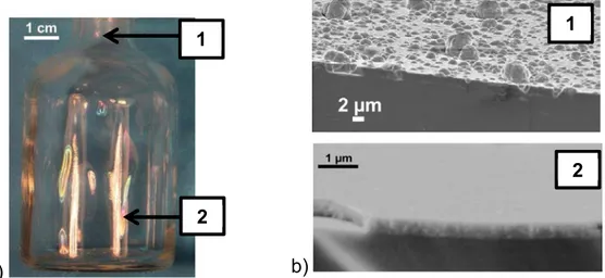
A macroscopic observation of the coated bottle reveals colorful iridescences which indicate effective deposition on the entire internal surface, but with thickness variations. Figure 4 presents a photograph of a coated glass bottle with iridescences at the bottom part and a macroscopic white
stain at the entrance and the corresponding SEM cross-section micrographs. The coating morphology at the bottom on the lateral walls looks dense and smooth, i.e. it matches exactly the glass surface, in agreement with previous studies [13]. At the bottle inlet, a smooth and glassy layer also exists but with spherical sub-micrometric nodules at the film surface. Krumdieck et al. [15] also noticed this phenomenon during deposition of Al2O3 from ATI on stainless steel using
pulsed-pressure MOCVD. They correlated the surface morphology with the process i.e. the generation of pulsed concentrated precursor droplets heated and pyrolysed close to the surface. This phenomenon could also be related to gas phase nucleation or homogeneous reactions of ATI, high growth rate or misalignment of the nozzle with the glass bottle. EDX measurements indicate that no carbon is present in the coating. Alumina thin films deposited in the equivalent operating conditions on Si substrate do not diffract X-rays [11-13, 15].
a)
b)
Fig. 4 : (a) Photograph of a coated glass bottle and (b) SEM cross-section micrographs of alumina coatings
The hydrolytic resistance was measured on three bottles, coated in the same processing conditions. Because of the low capacity (50 ml) of the bottles, results are extrapolated to 100 ml with respect to the European pharmacopoeia [20]. The mean hydrolytic stability of the coated bottles corresponds to a volume of 0.27 ± 0.01 ml of 0.01M HCl. This value favorably compares with that of uncoated glass bottle, which is 3.3 ml of 0.01M HCl. It thus appears that alumina coatings on soda-lime glass bottles present excellent performances improving the hydrolytic resistance of uncoated bottles.
Conclusions
Alumina coatings were processed on glass bottles by MOCVD from ATI at 666 Pa in a vertical hot-wall reactor. A numerical model based on an apparent heterogeneous kinetic law was established from operating conditions to simulate the deposition of alumina. The good agreement between the experimental and the calculated thickness profiles validates the process model for the tested conditions. The results point up high film thicknesses at the bottle entrance due to high ATI molar fractions and high gas convective flux. The model allows better understanding the chemical and physical phenomena occurring inside the bottle. The coating morphology is dense and smooth on the internal walls except at the bottle entrance where spherical nodules are present at the surface. It is expected that the model will help optimizing the process in order to obtain uniform thickness profiles of smooth alumina films. The first results obtained for hydrolytic resistance reveal excellent performances of the amorphous alumina films.
Acknowledgments
We are indebted to Hervé Guillon, Kemstream Montpellier for advice on the operation of the DLI facility.
1
2 2
References
[1] D.H. Kuo, B.-Y. Cheung, R.-J. Wu, Thin Solid Films 398–399 (2001) 35. [2] L. Wu, J. Wu, L. Zhao, C. Jiang, Ceram. Int. 33 (2007) 747.
[3] M. Voigt, M. Sokolowski, Mater. Sci. Eng., B, Solid-State Mater. Adv. Technol. 109 (2004) 99. [4] R. M’Saoubi, S. Ruppi, CIRP Annals – Manufacturing Technology 58 (2009) 57.
[5] K. Haas-Santo, M. Fichtner, K. Schubert, Appl. Catal. A General 220 (2001) 79.
[6] J. Masalski, J. Gluszek, J. Zabrzeski, K. Nitsch, P. Gluszek, Thin Solid Films 349 (1999) 186. [7] R. Emmerich, B. Enders, H. Martin, F. Stippich, G.K. Wolf, P.E. Andersen, J. Kudelha, P. Lukac, H. Hasuyama, Y. Shima, Surf. Coat. Technol. 89 (1997) 47.
[8] C.F. Stuller, P.J. Kelly, N.J. Copeland, Surf. Coat. Tech. 241 (2014) 130-137.
[9] T. Hirvikorpi, R. Laine, M. Vähä-Nissi, V. Kilpi, E. Salo, W.-M. Li, S. Lindfors, J. Vartiainen, E. Kenttä, J. Nikkola, A. Harlin, J. Kostamo, Thin Solid Films 550 (2014) 164.
[10] M.D. Groner, F.H. Fabreguette, J.W. Elam, S.M. George Chem. Mater. 16 (2004) 639 [11] M.-M. Sovar, D. Samélor, A.N. Gleizes, C. Vahlas, Surf. Coat. Tech. 201 (2007) 9159. [12] A.N. Gleizes, M.-M. Sovar, D. Samélor, C. Vahlas Adv. Sci. Tech. 45 (2006) 1184.
[13] S.K. Soni, D. Samélor, B.W. Sheldon, C. Vahlas, A.N. Gleizes, Electrochem. Soc. 25, 8 (2009) 1309.
[14] H. Vergnes, D. Samélor, A.N. Gleizes, C. Vahlas, B. Caussat, Chem. Vap. Dep. 17 (2011) 181. [15] S. Krumdieck, S. Davies, C. M. Bishop, T. Kemmitt, J.V. Kennedyn Surf. Coat. Tech. 230 (2013) 208.
[16] M. Manin, S. Thollon, F. Emieux, G. Berthome, M. Pons, H. Guillon, Surf. Coat. Tech 200 (2005) 1424.
[17] J. Mungkalasiri, L. Bedel, F. Emieux, J. Doré, F.N.R. Renaud, F. Maury, Surf. Coat. Tech. 204 (2009) 887.
[18] N.Y. Turova, V.A. Kozunov, A.I. Yanovskii, N.G. Bokii, Y.T. Struchkov, B. L. Tarnopol’skii, J. Inorg. Nucl. Chem. 41 (1979) 5.
[19] R.B. Bird, W.E. Stewart, E.N. Lightfoot, Transport Phenomena, second ed., John Wiley & Sons, 2007.