HAL Id: hal-00982817
https://hal.archives-ouvertes.fr/hal-00982817
Submitted on 24 Apr 2014
HAL is a multi-disciplinary open access archive for the deposit and dissemination of sci-entific research documents, whether they are pub-lished or not. The documents may come from teaching and research institutions in France or abroad, or from public or private research centers.
L’archive ouverte pluridisciplinaire HAL, est destinée au dépôt et à la diffusion de documents scientifiques de niveau recherche, publiés ou non, émanant des établissements d’enseignement et de recherche français ou étrangers, des laboratoires publics ou privés.
Development of a feedstock formulation based on
polypropylene for micro-powder soft embossing process
of 316L stainless steel micro-channel part
Mohamed Lakdhar Sahli, Jean-Claude Gelin
To cite this version:
Mohamed Lakdhar Sahli, Jean-Claude Gelin. Development of a feedstock formulation based on polypropylene for micro-powder soft embossing process of 316L stainless steel micro-channel part. International Journal of Advanced Manufacturing Technology, Springer Verlag, 2013, 69, pp.2139 -2148. �10.1007/s00170-013-5170-z�. �hal-00982817�
DEVELOPMENT OF A FEEDSTOCK FORMULATION BASED ON
POLYPROPYLENE FOR MICRO POWDER SOFT EMBOSSING PROCESS OF 316L STAINLESS STEEL MICRO-CHANNEL PART
M. Sahli* and J-C Gelin
Femto-ST Institute, Applied Mechanics Dept., UMR 6174 CNRS, ENSMM, 25030 Besancon cedex, France
Mohamed.sahli@ens2m.fr
Abstract. To exploit the potential of micro-system technology, the micro-powder embossing process,
a rapid manufacturing production technology of micro structured die mould, was currently being investigated. Present work focused on establishing a suitable binder system for micro-powder embossing process. Multi-component binder systems, comprising of different weight percentages of Paraffin Wax (PW), Stearic acid (SA) and Polypropylene (PP) were investigated. The compatibility between binder constituents was studied by Thermogravimetric analysis (TGA) showing a partial miscibility between both components. The feedstock comprised of 316L stainless steel powder and a wax-based thermoplastic binder was used to achieve a feedstock with 60 to 68% vol. powder loading. The degradation temperature of binders was determined by using Thermogravimetric analysis (TGA) and flow behaviour through rheometer. Homogeneity of the feedstock was verified by using Thermogravimetric analysis (TGA) and Scanning Electron Microscopy (SEM). Then, hot embossing was done and it was found that the feedstocks having solid loading up to 68 vol% were successfully embossed and components were without physical defects.
The polymeric part was driven off by thermal debinding using a thermal cycle designed on the basis of a thermogravimetric study of the binder. Finally the vacuum sintering of the parts allow high quality parts to be obtained.
Key words. Hot embossing, binder system, 316L stainless steel, rheological characteristics,
homogeneity.
1. INTRODUCTION
Hot embossing is a significant processing method for polymer-based micro-fabrication. It provides several advantages such as low-cost for moulds, high replication accuracy for micro-features and simple operation [1, 2]. In the last few years, hot embossing is being explored as a shaping method for the fabrication of micro-structured die mould for thermoplastic moulding applications, characterized by very low roughness (<0.01 m), such as micro-fluidic systems. In hot-embossing, both the base polymer substrate and the master die are heated above the glass transition temperature (or softening point) of the thermoplastic and a controlled force is applied. The assembly is then cooled below the glass transition temperature after which the substrate is separated from the mould/die.
In recent years, many studies have been conducted to investigate the hot embossing process. As example, the pressure distributions on the surface of polymer during hot embossing process have been investigated. The results indicate that a higher embossing pressure results in more uniform shrinkage in the elastically deformed state during cooling [3]. Becker and Heim [4] demonstrated that the hot embossing process could enable microstructures replication with high aspect ratio (height/section) over large thermoplastic polymer areas. The metal embossing process consists of four steps. Initially, metal powders are mixed with suitable organic binders. Binder is added between metal powder particles as the flow-vehicle to get embossed micro-parts of the desired shape. The embossing mixture of binder and powder is called feedstock. During embossing, the feedstock flows into and fills a
mould under heat and pressure to form a green part with the desired shape. The embossed micro-part then undergoes a debinding step where the polymer is extracted out and the powder is sintered to get full or near full density. This process enables the use of a wide range of materials such as those with high strength, hardness or other functional properties, which will broaden the applications of micro-components. Various investigations have been conducted, concerning the influence of physical or processing parameters such as size and loading rate of the powder in the mixture, the sintering temperature on the control and dimensional changes; density; mechanical properties and roughness surfaces of components have received increasing attention in recent years [5]. Meng et al. [6] have conducted an experimental analysis on replication of micro-fluidic system by micro powder injection moulding using 316L stainless steel. In addition, they have also investigated the dimensional change and surface roughness of the micro-mixer. They obtained in this study, the proper replication with appropriate shape retention and without visible defects by powder injection moulding using 316L stainless steel. The dimensional shrinkage of the micro-mixer took place mainly in the sintering step, whilst the dimensional change was not noticeable in the debinding step. The surface topography of the silicon mould insert was well replicated in the stainless steel micro-mixer.
Recently, Tay et al. [7] have succeeded in the manufacturing of micro-gears using the micro-powder injection moulding process with 316L stainless steel powder possessing particle sizes of 2.4 m and a multi-component wax-based binder system. The analysis revealed different grain structures at the tooth (≈35 m) and hub of the micro-gear (≈ 5 m). Significant grain growth was also observed at the tooth. Meng et al. [8] conducted an experimental analysis on the replication of a micro-fluidic system by micro-powder injection moulding using 316L stainless steel. Additionally, they also investigated the dimensional change and surface roughness of the micro-mixer. They obtained proper replication with appropriate shape retention lacking in visible defects by use of a powder injection moulding process with a 316L stainless steel feedstock. The dimensional shrinkage of the micro-mixer occurred mainly in the sintering step, whilst the dimensional change was not noticeable in the debinding step. The surface topography of the silicon mould insert was properly replicated in the stainless steel micro-mixer. German et al. [9] investigated the effect of powder loading on the in situ dimensional change during solvent debinding of powder injection moulded components. Tseng [10] evaluated the influence of powder loading on the dimensional control in ceramic injection moulding using a statistical analysis. Fu et al. [11] investigated the manufacturing of a 316L stainless steel cylindrical micro-structure array using a silicon mould insert with the hot embossing process. Their results demonstrated the effects of various embossing parameters on the filling of cavities in the silicon mould insert and the de-moulding of micro-structures. Meng et al. [12] have conducted an experimental analysis on the dimensional change and surface roughness of replication of micro-fluidic system by micro powder injection moulding using 316L stainless steel. They obtained the well replication with good shape retention and without visible defects. The dimensional shrinkage took place mainly in the sintering step. The surface topography of the silicon mould insert was well replicated in the stainless steel micro-mixer.
This study uses the lithography technology to fabricate the silicon mould insert with nanoscale details and surface roughness at a lower cost. Due to the mechanical strength limitation, silicon material is usually not suitable to use as mould material. In this study, the silicon master was used for casting of silicone to fabricate elastomeric micro-fluidic mould. The choice to use a flexible mould was related to the de-moulding facilities for the micro-structures and the increase of lifetime of the mould when used in the hot embossing process. In this study, the whole process is examined using 316L stainless steel, known by their good mechanical properties and corrosion resistance, behaviour suitable for a wide range of applications. The thermo-physical and rheological characterisation, and feasibility of the feedstock using a multi-component binder system for micro hot embossing of a micro-fluidic system, is reported in this paper. The work covers the determination of a suitable powder loading for feedstock preparation, evaluation of the feedstock homogeneity, thermal characteristics and mechanical properties, in using properly formulated binders, as well as the morphology of the microstructures.
2. MATERIALS AND EXPERIMENTAL WORKS 2.1. Materials
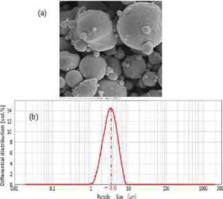
Fine powders of 316L stainless steel were used to develop the mixtures dedicated to the hot embossing process. The powder particulates had a spherical shape and an average particle size equal to 5 µm (Fig. 1a). This shape is generally more appropriate for obtainning a feedstock with a low viscosity. The powders had a density equal to 7.9 g.cm-3 and were provided by Sandvik Osprey Company®. Fig. 1b gives a photographs of the 316L stainless steel powder particle distribution. The binder system consists of paraffin wax (PW), stearic acid (SA) and polypropylene (PP) where the highest melting temperature of the binder system measured on a Setaram differential scanning calorimeter (DSC 92) is 160 °C. The lowest degradation start temperature of the binder system measured on a Setaram® thermogravimetric analyser is 180 °C. The character istics of the different binder systems were related in Table 1.
Figure 1. (a) scanning electron micrograph, (b) particle size distribution for 316L stainless steel
2.2. Rheology characterisation and thermogravimetric analysis (TGA)
The rheological behaviour of the feedstock was measured using a capillary rheometer provided by Instruments Bohlin®. A series of experiments were performed in which the samples were extruded through a die with a 1 mm diameter and measuring 16 mm in length. Three different temperatures 170 °C, 190 °C and 210 °C were used. Shear rates of 102 to 104 s-1 were applied using the die with the measurements reported above, giving a ratio (L/D) equal to 16.
The degradation temperature ranges of the binder components in the powder-binder feedstocks were obtained from thermogravimetric analyses (TGA) using a Setaram Setsys analyser®. The analysis results were essential to determine the maximum embossing temperature and removal of binder in thermal debinding cycle. Thermogravimetric analysis was carried out in the temperature range 25 - 500 °C at a heating rate of 10 °C/min.
Table 1. Characterisation of the different binder components
Binders Density Melting temperature Degradation temperature range
Stearic acid (SA) 0.890 70 °C 180-280 °C Paraffin wax (PW) 0.910 60 °C 200-330 °C Polypropylene (PP) 0.900 160 °C 340-450 °C 2.3. Mixing tests and soft embossing process
Experiments related to the mixing of binders and feedstocks were carried out using a Brabender® Plastograph EC mixer with a pair of rotor blades. The maximum capacity of the mixing chamber was 55 cm3. The mixtures were prepared with different vol.% incremental solid loadings from 20 vol.% up to 80 vol.% with an incremental increase of 5% for each level. The mixing temperature was set at 170 °C, which is within the highest melting temperature (160 °C). This allowed complete melting and prevented total binder degradation. During mixing, the binder system was fed at first followed by the addition of powder in small consecutive loadings. The embossing tests were carried out to an imposed displacement, equal to 1mm, using an universal testing machine (type 6025, Instron®). Soft embossing was carried out above the upper melting point of the feedstock at 170 °C in a micro -structured mould.
2.4. Fabrication of micro-fluidic system
The silicon (Si) mould master was fabricated with micro-fluidic structure by means of photolithography and Deep Reactive Ion Etched technique (DRIE) to emboss micro- fluidic structure on stainless steel 316L feedstocks (Fig. 2). The dies were fabricated as follows. Firstly, the wafer was cleaned in piranha solution for 2 min followed by de-ionized water rinse for 2min and dehydration on a hotplate at 110 °C for 5 min. A 2.5 µm thick SPR220 positive photoresist was deposited on the surface of the wafer using a spin coater using a spin speed of 1200 rpm and a spinning time of 30 s and then soft baked at 115 °C for 15 min on a hot plate , then cooled down to room temperature. The resist was exposed using an EVG®620 automated mask alignment with an energy of 300 mJ/cm2.
The DRIE was performed on Alcatel A601 machine with the Bosch process technology. Silicon structures with depth of approximately 100 µm were obtained. Finally, the dies were treated with C4F8 gas under a flow of 500 sccm for 5 min to
create a thin layer of Teflon-like material on the sidewall surfaces to further facilitate mould release and to reduce the friction between Si die mould and elastomeric replicas during de-moulding. The silicone rubber (Sylgard 184) provided by Dow Corning Inc® was used as the material for the elastomeric moulds. A silicone base and catalyst were thoroughly mixed with a ratio 1:1. The mixture was degassed during approximately 5 min in primary vacuum to avoid air trapped in the silicone leading to a porous matrix and defects in the resulting replicas. Next, it was poured over the Si master and cured at 70 °C during 4 h. F ig. 3a shows micrographs of patterned on silicone elastomeric substrates used in this study. Example of schematic drawing with dimensions of the micro-structures of the elastomeric mould is shown in Figure 3b. The forming temperature of the proposed feedstock was tested in the range of 170 to 210 °C.
Figure 2. SEM micrographs of silicon master mould: (a) reservoir and (b) channel.
Figure 3. (a) Elastomeric die cavity mould, (b) definition of mould size dimension for µfluidic
geometries. 2.5. Debinding and sintering stages
Firstly, the debinding was performed at 500 °C in a thermal oven. The embossed parts were placed on an Al2O3 plae. The debinding temperature used was based on
the TGA curve identified for the binder system. Because the SA and PW finish begin to degrade at approximately 330 °C, the first debin ding temperature used was 350 °C. The temperature was then gradually increased to 500 °C, which corresponding to the TGA curve that leads to a significant loss of polypropylene weight and the removal of all residual binder. Secondly, the stage of solid state sintering process was conducted in vacuum furnace with graphite heating element offering a maximum temperature of 1900 °C. The temperature were increa sed up to 1000 -1360 °C, with 0.1 °C/min to 10 °C/min for 316L stainless.
3. RESULTS AND DISCUSSIONS 3.1. Thermo properties
The thermal properties of the binders provide basic guidelines for subsequent replication process steps. Fig. 4a shows the differential scanning calorimetry result of the binders where three endothermic peaks, 60 °C, 7 0 °C and 170 °C, were observed during heating due to the melting of major binder components. From the differential scanning calorimetry result, the melt temperature for hot embossing process should be higher than 170 °C so as to enable complete fill ing of the micro-cavities.
Figure 4. (a) Differential scanning calorimetry result of binders, (b) TGA curves of all binders and the
combined binder systems (PW 55 %, PP 40 %, SA 5 %).
The degradation temperature ranges, as related to the binder components in the powder/binder feedstocks, were obtained by thermogravimetric analyses (TGA), which were performed using a Setaram Setsys analyser®. Fig. 4b shows the TGA curves of the multi-component binder and the individual binder components. In the TG curves collected above 180, 200 and 340 °C, the stearic acid, paraffin wax and
polypropylene each start to decompose, respectively. Additionally, each degradation temperature range is very broad, and the associated mass percentage loss of each of the three materials tends to 0 % (complete loss) at higher temperatures, which is the ideal case for binder removal in debinding of the Metal Injection Molded (MIM) part. Similarly, the multi-component binder, which resulted from mixing of the individual binder components, also underwent two distinct degradation steps. Through a comparison of the TGA curves, it is reasonable that the full degradation of PW and SA occurred in the first degradation temperature range (180 - 330 °C), whereas the degradation of PP took place at the higher temperatures (340 - 450 °C). Above 450 °C, all of the binder components were bur ned off. Based on the TGA results, a multi-step debinding profile was established, demonstrating the progressive removal of each of the three binder components. The progressive debinding over a wide temperature range can help to retain the integrity of the micro-structured cavities and prevent the formation of debinding defects, such as cracking and slumping.
The thermograms of Fig. 5 indicate a significant decrease in weight loss of the blends. The results show that the thermal stability of blends decreases with an increase in wax content. A decomposition was registered around 450 °C, except for the compound containing that the PW virgin whose decomposition finished around 330 °C and the decomposition process ended around 5 00 °C.
Figure 5.TGA curves for (a) 100% PW; (b) 80/20 PW/PP blend; (c) 60/40 PW/PP blend; (d) 40/60 PW/PP blend; (e) 20/80 PW/PP blend and (f) 100% PP.
3.2. Mixing behaviour and powder loading
In order to study the effect of the loading rate of each component on the rheological properties of feedstock suitable for filling micro-cavities in hot embossing process, three different mixtures with two starting components were carried out. In the mixing tests, the component loading of each PW or 316L stainless powder was increased gradually from 0% to 100% by adding the PW or 316L stainless powder with an increment equal to 5% for each level. The mixing torque vs. mixing time is related in Fig. 6a. The related mix torques corresponding in the combines (PW, PP) evolves the same way with lower values then (PP, 316L stainless). We can conclude that using more paraffin wax can reduce the viscosity of the mixture and using the
polypropylene gives component rigidity to the embossed. On the basis of these comments, this study will be realised using the feedstocks prepared, using two different formulations (F1 : 28wt.% PW + 2wt.% SA + 10wt.% PP; F2 : 10wt.% PW + 2wt.% SA + 28wt.% PP).
Figure 6. Mixing torque vs. powder volume loading, obtained through the continuously rising powder
loading technique (a) at 170 °C and mixing time 30 min, (b) feedstock formulation F1 and F2, mixing time: 60 min, mixing temperature: 170 °C.
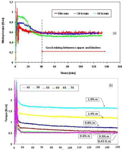
Mixing tests by continuously increasing powder loading were also realised to determine the critical solid loading using the two formulations. The powder loading was increased gradually from 20% to 80% by adding the powders with an increment equal to 5% for each level. The mixing torque vs. mixing time is related in Figure 6b. Three different zones appear looking the curve in Fig. 6b. In zone 1, there is mainly binder in the mixture and the torque remains almost at the same low level. In zone 2 (F1: 50% to 65%, F2: 50% to 70%) the torque begins to slightly increase starting from powder loading equal to 50%. In zone 3, the torque increases rapidly from 70% or 80% depending on the chosen formulation, to the maximal powder loaded feedstock corresponding to 70% or 80%. So in relation with this incremental test, the critical solid volume loading was determined for F1, F2 equal to 70% and 80%, respectively. It results that the mixing torques using formulation 1 were smaller than the torques of the next test using formulation 2 for the same powder loading as shown in Fig. 6b. Fig. 7a shows the variation in the torque with time during the mixing experiments. The experiments were performed for a mixing temperature of 170 ºC (according to ATG tests) and mixer speeds values: 10, 30 and 50 rpm. For a given powder particle loading, it was observed that an increase the mixing speed results in a decrease in the mixing torque. Reducing the mixing time, below 40min, results in a high
heterogeneity of feedstocks. However, in this case, steady state torque was not achieved. The proper mixing conditions were obtained from a temperature, speed and mixing time equal to 170 °C, 50 rpm and 60 min, respectively.
Fig. 7b shows the torque evolution for feedstock with a different reloading powder, using formulation 2. The torque stabilizes at a steady level in a short time (60 min) indicating uniform mixing. The torque value increases as the powder loading varies from 45 vol.% to 70vol.% due to the higher powder content. It is proportional to the shear stress of the mixer, which indicates the work energy consumed to disperse and distribute the powder in the binder.
Figure 7. (a) Torque vs. mixing time profiles associated to the feedstocks with different mixing
velocity, (b) mixing behaviour for six different powder loadings, Formulation 2.
The scanning electron micrographs of the feedstock were shown in Fig. 8. In the figure, stainless steel and binder system could be distinguished due to various contrast levels caused by different levels of atomic number. Stainless steel appears brighter than the binder system due to more back-scattered electrons released by virtue of its higher atomic number. For the mixed feedstock, the particles disperse homogeneously into the matrix and were surrounded by the binder. Finally, the proper parameters in the mixing tests were 170 °C f or the mixing temperature, 50 rpm as the mixing rotation speed and 60 min for mixing time, but the weight of the powders were different.
Figure 8. SEM photo of feedstock (powder volume loading equal 60%) after mixing stage used in the
proposed investigations.
3.3. Rheological characteristics
Fig. 7a shows the results from the capillary rheometer in term of shear viscosity vs. shear rate curves of the mixed feedstock (from F1 and F2, 316L stainless steel powder, D50=5 m) tested at 170 °C. According to the viscosity cur ves related in
Figure 9a, the formulations F1 and F2 give a similar behaviour for 316L stainless steel powder. The viscosity of the feedstock decreases with shear rate, indicating pseudo-plastic flow behaviour. Normally, feedstock exhibiting pseudo-plastic flow during embossing eases cavities filling. As shown in the figure 9b, the viscosity is also temperature sensitive, decreasing with increasing temperature.
Figure 9. Shear viscosity vs. shear rate corresponding to (a) feedstock formulations F1 and F2
3.4. Debinding and sintering results
To investigate the micro-replication feasibility of the feedstock for hot embossing, subsequent processing steps were conducted. For this, it is of interest to examine cylindrical samples compacted at different stages of manufacturing. The cylindrical samples (Ø 6 mm × 10 mm) were successfully compacted using two formulations, already presented previously. The samples after compaction (green bodies) were debound and sintered under the conditions imposed in the cycle and according to the TGA analysis. As example, on compacted samples with formulation 1, it was found that for a speed V1, from 1 to 10 °C/min, all samples underwent a slum ping, whatever
the value of speed V2. For a speed V1 equal to 0.1 °C/min, the sample was cracked
with distortion, for V2 equal to 2 at 10 °C/min. Decreasing the second spe ed, V2 at 1
°C/min, was conducted, no visual defects such as cr acks, bubbles, slumping, distortion or cracking were observed (see Fig. 10). From a rheological point of view, a formulation F1 was more fluid than F2 but also more sensitive to the first level of the debinding since it contains more paraffin.
Figure 10. Dedound and sintering of cylindrical samples at different conditions: (a) F1 and (b) F2.
3.5. Fabrication of micro-fluidic die mould
In order to allow to investigate the influence of forming temperature on the filling stage and replication accuracy during the hot embossing process, set of experiments were performed. From 170°C to 210°C, the imposed he ating rate was 5°C/s, the hot embossing time was also 5min and an imposed displacement was set to 1mm. In this case, the final qualities of metallic replicas using two different feedstock (F1, F2), described previously, were measured with Scanning mechanical microscope (SMM) to determine dimensions and surface roughness. Fig. 11 shows the side view of the embossed reservoirs where the walls of the microstructures were successfully replicated. The down surfaces of the reservoirs and channels were flat, indicating good filling during hot embossing process. The feedstocks gradually fill the cavities of the elastomeric mould when increasing the forming temperature. The surface roughness was much lower in the replicas made from a feedstock 1 (F1) as the
feedstock 2 (F2). So the surface of replicated parts were smooth with Ra<0.1µm
using feedstock 1. It can be related to the fact that a decreasing viscosity was favourable to decrease surface roughness. The microstructures were debound and sintered. The debound micro-fluidic systems have no visual defects such as slumping, distortion or cracking.
Figure 11. 3D topographies imprint of 316L stainless steel replicas realised though soft embossing
process at different forming temperatures. 4. CONCLUSIONS
316 stainless steel feedstock using a multi-component binder system consisting of PW and PP was produced for the micro hot embossing of micro-fluidic systems. A study of the influence of feedstock fluidity on filling rate of cavities and roughness surface replicas were performed. Two kinds of formulations were used to obtain feedstocks with different solid loading contents. The findings can be summarized as follows:
1) DSC and TGA show that hot embossing of the feedstock should be carried out above 160 °C (i.e. the upper melting temperature) b ut below 250 °C as beyond which the binder components paraffin wax and stearic acid start degrading.
2) The torque measurements of mixtures of binder and 316L stainless steel reveal that the stearic acid reduces the viscosity. Besides, torque values also increase when polypropylene quantity increases indicating a higher viscosity. We can also observe that torque values were higher when powder loading increases.
3) Rheological tests show that the feedstocks exhibit pseudoplastic flow behaviour and moldability. From rheological measurements it was observed that viscosity of all the feedstocks decreases when the shear rate increase.
4) Based on the thermal and rheological characterisations of the feedstock, the feasibility of the feedstocks for hot embossing of micro-fluidic systems was investigated. The results show that micro-structures can be successfully fabricated. The microstructures have the necessary strength for demolding, there have no visual debinding defects and the final sintered microstructures have good shape retention.
5) Finally, from the experiments carried out, it was concluded that, binder formulations and MIM feedstocks were shown a pseudo-plastic flow behavior and suitable for hot embossing. The addition of steatite powder to the binder formulations increased the viscosity of the feedstocks.
REFERENCES
1. Juang Y.-J., James L.L., Hot embossing in microfabrication, I. Experimental, Polym. Eng. Sci., 42, 539-550, (2002)
2. Juang Y.-J., James L.L., Hot embossing in microfabrication. II. Rheological characterization and process analysis, Polym. Eng. Sci., 42, 871-888, (2002)
3. Lin C.-R., Chen R.-H., Hung C., Preventing non-uniform shrinkage in open-die hot embossing of PMMA microstructures, J. Mater. Process. Technol., 140, 173-178, (2003).
4. Becker H., Heim U., Hot embossing as a method for the fabrication of polymer high aspect ratio structures, Sens. Actuators, 83, 130–135, (2000).
5. Heaney D. F., Spina R, Journal of Materials Processing Technolgy, 191, 385-390, (2007).
6. Meng J., Loh N. H., Fu G., Tor S. B.and Tay B. Y., Replication and characterization of 316L stainless steel micro-mixer by micro powder injection moulding, Journal of Alloys and Compounds, 496, 293-299, (2010).
7. .BY. Tay, NH. Loh, SB. Tor, FL. Ng, G. Fu, XH. Lu, Characterisation of micro gears produced by micro powder injection moulding, Powder Tech. 188 (2009) 179-182.
8. J. Meng, NH. Loh, G. Fu, SB. Tor, BY. Tay, Replication and characterization of 316L stainless steel micro-mixer by micro powder injection moulding, J.Alloys Comp. 496 (2010) 293-299.
9. R.M. German, E.J. Westcot, C. Binet: International Journal of Powder Metallurgy, 46-1, 2003, pp. 61-67.
10. W.J. Tseng: Journal of Materials Processing Technology, 79-1-3, 1998, pp. 242-250.
11. G. Fu, SB. Tor, NH. Loh, DE. Hardt, Micro-hot-embossing of 316L stainless steel micro-structures, Appl. Phys. 97 (2009) 925-931.
12. L. Moballegh, J. Morshedian and M. Esfandeh, Copper injection moulding using a thermoplastic binder based on paraffin wax, Materials Letters 59, 2005, pp. 2832-2837.
13. J. Meng, N.H. Loh, G. Fu, S.B. Tor and B.Y. Tay, Replication and characterization of 316L stainless steel micro-mixer by micro powder injection moulding, Journal of Alloys and Compounds 496 (2010) 293-299.