Development of a Liquid-Fueled Micro-Combustor
by
Jhongwoo Jay Peck
B.S. Mechanical and Aerospace Engineering, Seoul National University, 2001 S.M. Aeronautics and Astronautics, Massachusetts Institute of Technology, 2003
Submitted to the Department of Aeronautics and Astronautics in partial fulfillment of the requirements for the degree of
Doctor of Philosophy
at the
MASSACHUSETTS INSTITUTE OF TECHNOLOGY
June 2008
Author.
@ Massachusetts Institute of Technology 2008. All rights reserved.
2 Department of Aeronautics and Astronautics
^ May 23, 2008
Certified by...
Ian A. Waitz erome C. Hunsaker Professor He) of the Department,~ikeroiaautics and Astronautics Thesis Supervisor Certified by...
//
/ Certified by... .. ... Alan H. Epstein R. C. MacLaurin Professor obuart A. Jacobson rPrincipal Research EngineerAccepted by ... --- c I• ,
-MASSACHU
S !NsT
OF TECHNOLOGYAUG 0 1 2008
ISRARIESDavid L. Darmofal
UAssociate Department Head Chair, Committee on Graduate Students
Development of a Liquid-Fueled Micro-Combustor
by
Jhongwoo Jay Peck
Submitted to the Department of Aeronautics and Astronautics on May 23, 2008, in partial fulfillment of the
requirements for the degree of Doctor of Philosophy
Abstract
Advances in Micro-Electro-Mechanical Systems (MEMS) have made possible the de-velopment of shirtbutton-sized gas turbine engines for use as portable power sources. As part of an effort to develop a microscale gas turbine engine, this thesis presents the modeling, design, fabrication, and experimental characterization of a micro-combustor that catalytically burns JP8 fuel. Due to high energy densities stored in hydrocarbon fuels, microscale heat engines based on them are estimated to have specific energies about one order of magnitude higher than those of current battery systems. In addition, utilizing a commonly available logistics fuel would provide ad-vantages for military applications. Thus, a microengine burning JP8 fuel is attractive as a portable power source and potential replacement for batteries.
The thesis first presents a number of models developed to design the fuel vapor-izer, the fuel-air mixing chamber, and the combustion chamber. Among these is a reduced-order mass transfer model that simulates catalytic combustion of a slow-diffusing hydrocarbon fuel. A two-phase heat transfer model was also developed to design an on-board fuel vaporizer with an array of micro-channels. Using the model results, a liquid-fueled micro-combustor test rig with a combustion chamber volume of 1.4cc and an overall die size of 36.4 mm x 36.4 mm x 6.5 mm was built. This device is a hybrid structure composed of silicon, sapphire, and glass. Deep reactive ion etching was mainly used to fabricate the silicon parts. The sapphire and glass parts were built by ultrasonic machining.
The liquid-fueled micro-combustor was then experimentally characterized. Two configurations were tested and compared; one with the whole combustion chamber filled with a catalyst, and the other with a catalyst filling the chamber only partially. In the fully-loaded configuration, JP8 combustion was stably sustained at mass flow rates up to 0.1 g/sec, and an exit gas temperature of 780 K, an overall combustor efficiency of 19%, and a power density of 43 MW/m3 were achieved. The primary limitation on increasing the mass flow rates and temperatures further was structural failure of the device due to thermal stresses. With the partially-loaded configuration,
a mass flow rate of 0.2 g/sec, and a corresponding power density of 54 MW/mrn3 were obtained. The exit gas temperature for the partially-loaded configuration was as high as 720 K, and the maximum overall efficiency was over 22%. Although the reduced amount of catalyst led to incomplete combustion, smaller thermal losses resulted in an increase in the overall combustor efficiencies and power densities. The overall effi-ciency and the exit gas temperature were lower than the operational requirement of the microengine in both of the device configurations. A non-dimensional operating map was constructed based on the experiment, and suggestions for future liquid-fueled micro-combustors were made; to achieve maximum efficiency for a volume as small as possible, improving the thermal efficiency would be necessary.
Thesis keywords: Power-MEMS, microengine, micro-combustor, catalytic
combus-tion, JP8 combustor, micro fuel vaporizer, micro-fabricacombus-tion, deep reactive ion etch-ing
Thesis Supervisor: Ian A. Waitz Title: Jerome C. Hunsaker Professor
Acknowledgments
This thesis was completed with help of many people. First and foremost, I sincerely thank my advisor Professor Ian Waitz. His extraordinary guidance and encourage-ment made this work possible, and he deserves the greatest acknowledgencourage-ment.
Professor Alan Epstein served as a member of my thesis committee. I am thankful for his insightful advice during the course of this research. I am truly grateful also to Dr. Stuart Jacobson for managing the microengine program and serving in the thesis committee. He provided precious advice throughout the research.
Dr. Chris Spadaccini and Professor Zolti Spakovszky willingly became readers of the thesis. I appreciate their valuable comments.
My gratitude extends to the fellow students who worked on the microengine project with me. Dr. Chiang Juay Teo has been a close friend and good counselor. Bernard Yen shared useful tips in the cleanroom.
Our wonderful micro-fabrication team also deserves thanks. Dr. Hanqing Li, Dr. Haifeng Dong, and Linhvu Ho provided helpful advice on the micro-fabrication. Dr. Woo Sik Kim, purely out of friendship, helped me with doing the micro-fabrication, coating catalysts, and taking SEM images.
During my stay in the Gas Turbine Laboratory, it was my privilege that I was raised by the excellent faculty. This includes Professor Jack Kerrebrock, Professor Edward Greitzer, Dr. Gerald Guenette, and Dr. Choon Tan. I also owe many thanks to the technical and administrative staff at the GTL: Dr. Yifang Gong, James LeTendre, Lori Martinez, Holly Anderson, Susan Parker, and Diana Park.
Robin Palazzolo at Professor Waitz's office, Marie Stuppard at the department office, and Maria Brennan at the Internaltional Student Office should also receive my special thanks as their aid was just as essential as the academic guidance.
Finally, I thank my parents and brother whose love and care carried me through. My wife Hyeju and my first son Nathan should be esteemed for their support.
This research was sponsored by DARPA and the U.S. Army Research Laboratory under the Collaborative Technology Alliance Program.
Contents
1 Introduction 23
1.1 Need for portable power sources . . ... .. . . 23
1.2 Power-M EM S ... 24
1.2.1 Applications ... 24
1.2.2 Pertinent technologies ... 25
1.3 MIT microengine ... 27
1.4 Motivation and objectives of the research . ... 32
1.5 Contributions of the research ... 35
1.6 Review of previous research ... 36
1.6.1 Previous MIT micro-combustor research . ... 36
1.6.2 Other microscale combustion research . ... 46
1.7 Micro-combustor challenges ... 48
1.7.1 Short residence time for high power density devices ... 49
1.7.2 Large heat loss ... 49
1.7.3 Materials and fabrication constraints . ... 51
1.7.4 Challenges specific to the use of liquid-fuels . ... 52
1.8 Organization of the thesis ... 54
2 Experimental Apparatus Design 57 2.1 M aterial selection ... 58
2.2 Combustor volume ... 59
2.2.1 Overview of the model ... .. 60
2.2.3 Results . . . . 2.2.4 Summary of the combustor volume model 2.3 Fuel vaporizer ...
2.3.1 Two-region heat transfer model . . . . 2.3.2 Results . . . . 2.3.3 Summary of the fuel vaporizer model . . . 2.4 Fuel injection holes and mixing chamber . . . . . 2.5 Packaging and fluid connections . . . . 2.6 Clam ps . . . . 2.7 Final design ...
2.8 Chapter summary ...
3 Apparatus Fabrication and Experimental Setup 3.1 Silicon micro-fabrication . . . .
3.1.1 Overview ...
3.1.2 Photolithography . . . . 3.1.3 Deep Reactive Ion Etching . . . . 3.1.4 Silicon fusion bonding . . . . 3.1.5 Silicon-to-glass anodic bonding . . . . 3.2 Ultrasonic machining . . . . 3.3 Preparation of the catalystic inserts . . . . 3.4 Experimental setup and diagnostics . . . . 3.5 Chapter summary ...
4 Experimental Characterization
4.1 Ignition procedure of catalytic combustion . . . . 4.2 Catalytic JP8 combustion . . . . 4.2.1 Temperature response . . . . . 4.2.2 Efficiency breakdown . . . . . 4.2.3 Non-dimensional operating map . . . . . . 4.3 Catalytically-anchored gas-phase combustion .
8 91 91 91 93 95 95 97 102 104 106 108 111 111 112 112 117 118 124 : : : : : : :
4.3.1 Temperature response ... 126
4.3.2 Efficiency breakdown ... 126
4.4 Device comparison ... 127
4.5 Catalytic combustor design case studies . . . ... 131
4.5.1 Case #1: Liquid-fueled micro-combustor revisited ... . 133
4.5.2 Case #2: Combustor for TPV application . ... 137
4.6 Performance of the fuel vaporizer ... 139
4.7 Assessment of device degradation . ... . 139
4.8 Chapter summary ... 143
5 Summary and Conclusions 145 5.1 Summary of research ... 145
5.2 Review of contributions ... 147
5.3 Recommendations for future work . ... . 149
A Drawings of Photomasks 151 B Mechanical Drawings of Ultrasonically Machined Parts 159 C Monte-Carlo Simulation on the Fuel Vaporizer Design Model 163 D Heat Loss Model 165 D.1 Convective heat loss ... 166
D.2 Radiative heat loss ... 167
D.3 Conductive heat loss ... 167
E Uncertainty Analysis on Experimental Measurements 169 E.1 Uncertainties in the independent measurements . ... 169
E.2 Uncertainties in the derived quantities . ... 170
E.2.1 Equivalence ratio ... 170
E.2.2 Overall combustor efficiency . ... 171
E.2.3 Chemical efficiency ... 172
E.2.4 Thermal efficiency ... 173 9
E.2.5 Peclet number ... ... 174
List of Figures
1-1 Potential for power-MEMS technologies . ... 26 1-2 Cross-sectional view of the MIT microengine (a) and schematic of the
fully packaged engine system (b) (Courtesy of Diana Park) ... 29 1-3 Schematic (a) and SEM image (b) of three-stack silicon micro-combustor
[1] . . . 38 1-4 Schematic (a) and SEM image (b) of six-wafer engine static structure [1] 40 1-5 Exit gas temperature (a) and combustor efficiency (b) vs. mass flow
rate for premixed hydrogen-air combustion in the six-wafer
micro-com bustor [1] . . . .
41
1-6 Combustor efficiency for six-wafer micro-combustor with ethylene-air
(a) and propane-air (b) [1] ... 42
1-7 Cross-sectional diagram of the dual-zone micro-combustor [2] .... . 44 1-8 Schematic of the catalytic micro-combustor (adapted from Spadaccini
[2]) . . . .. .. . 46 1-9 Development paths of the MIT micro-combustor ... 47 2-1 Definition of the control volume for the combustor volume design model 62 2-2 Results of the catalytic combustion model for various equivalence ratios
(tube diameter = 700M m, P = 2.0 atm) ... 69 2-3 Results of the catalytic combustion model for various tube diameters
( = 1.0, P = 2.0atm) ... .. 70
2-4 Results of the catalytic combustion model for various pressures (0 =
2-5 Final design of the combustion chamber layer . ... 72
2-6 Thermocouple locations ... . ... 72
2-7 Illustrative description of the two-region heat-transfer model .... . 74
2-8 Modeling results for various design cases (rhf = 0.04g/sec, D = 500 pm, and N = 49, unless otherwise noted) . ... 79
2-9 Final design of the fuel vaporizer layer (a) and a zoom-in view (b) . . 80
2-10 Fuel injection holes viewed from above (a) and below (b) ... 82
2-11 Penetration of a jet injected into a cross-flowing air [3] ... 82
2-12 Normalized coverage of the injected fuel vapor as a function of the hole diameter ... ... ... .. 83
2-13 Fuel-air mixing chamber layer . ... ... 83
2-14 Extended packaging block . ... ... 85
2-15 Finite element model of the extended packaging . ... 85
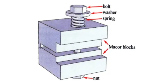
2-16 Schematic of a spring-laoded clamp that holds the parts together . . 86
2-17 Exploded view of the experimental apparatus . ... 88
2-18 Flow paths in the experimental apparatus . ... 88
2-19 Schematic of the experimental apparatus assembly ... 89
2-20 Schematic of the fully packaged test bed . ... . . 89
3-1 Label, material, features, and fabrication method for each part . . .. 92
3-2 Schematic description of the micro-fabrication procedure (not to scale) 94 3-3 Layer 1 after Deep Reactive Ion Etching . ... . 96
3-4 Infrared images taken during the silicon direct bonding: immediately after contact (a), after the voids were pressed down (b), and after annealing for an hour (c) . ... .... ... . 99
3-5 Picture of the bonded wafers for Layers 3 and 4 . ... 99
3-6 Front side of the completed silicon piece (showing the front side of Layer 3) ... .. ... .... .. ... ... 100
3-7 Back side of the completed silicon piece (showing the back side of Layer 4) ... .. ... ... 101
3-8 Schematic of anodic bonding between silicon and SD-2 glass . . . 101
3-9 SD-2 glass and silicon pieces mounted in an anodic bonding chuck . . 102
3-10 Electric current across the silicon-SD2 interface during anodic bonding under 1200V ... . 103
3-11 Layers 1 and 2 anodically bonded ... . 103
3-12 Picture of ultrasonically machined Layer 2 (SD-2 glass) . . . 104
3-13 Picture of ultrasonically machined Layer 5 (sapphire) . . . 105
3-14 Picture of ultrasonically machined exit tube (sapphire) . . . 105
3-15 Prepared catalytic insert ... 107
3-16 Test stand assembly built out of steel . ... 107
3-17 Complete test rig ... 108
3-18 Schematic of the experimental facility . ... 109
4-1 Photograph of the JP8 combustor in operation (a) and a zoomed view (b) . . . .... . . . .. . 113
4-2 Thermal infrared image of the liquid-fueled micro-combustor during JP8 combustion (0 = 1.1, rh = 0.1 g/sec) ... 114
4-3 JP8 combustion result: exit gas temperature vs. equivalence ratio for different mass flow rates ... 115
4-4 JP8 combustion result: exit gas temperature (a) and structural tem-perature (b) vs. mass flow rate for different equivalence ratios . . . . 116
4-5 JP8 combustion result: efficiency breakdown for ¢ = 1.1 . . . . 119
4-6 JP8 combustion result: Peclet number vs. mass flow rate . . . 121
4-7 JP8 combustion result: lines of constant Peclet numbers on a chemical efficiency and thermal efficiency plane . . . 122
4-8 JP8 combustion result: chemical efficiency (a) and thermal efficiency (b) vs. Peclet number ... .. 123
4-9 Relevant parameters divided into non-dimensional parameters . . . . 125
4-10 Partially-loaded catalytic micro-combustor result: temperatures vs. mass flow rate for -= 0.9 ... .... 127
4-11 Partially-loaded catalytic micro-combustor result: efficiencies vs. mass
flow rate for q = 0.9 ... .. ... 128
4-12 Device comparision: exit gas temperatures (a) and structural temper-atures (b) vs. mass flow rate for
4
= 0.9 . ... . 1294-13 Efficiency breakdown comparison between the fully-loaded and the partially-loaded catalytic combustors (0 = 0.9) . ... 130
4-14 Comparison of chemical efficiencies vs. Peclet number between the fully-loaded and the partially-loaded (with corrected Peclet number) catalytic combustors ... ... ... 131
4-15 Device comparison on a non-dimensional operating space ... 132
4-16 Non-dimensional operating map of liquid-fueled micro-combustor. .. 133
4-17 Peclet number vs. mass flow rate for all data acquired in the liquid-fueled micro-combustor ... ... 135
4-18 Thermal efficiencies vs. Peclet number for the liquid-fueled micro-combustor and the silicon micro-micro-combustor based on catalytic propane combustion ... .. .. ... ... 135
4-19 Non-dimensional operating map of silicon micro-combustor based on catalytic propane results (data obtained from Spadaccini [2]) ... 136
4-20 Boiling front formed in the middle of the fuel supply channel at low fuel flow rates ... ... 140
4-21 Fuel injection holes before testing (a) and after 10 hours of operation (b)141 4-22 Catalytic insert before testing (a) and after 10 hours of operation (b) 142 A-1 M ask # 1 ... ... .. ... .. ... . 151 A-2 M ask #2 ... ... .. ... ... . 152 A-3 Mask #3 ... .... .... .... ... ... ... 153 A-4 Mask #4 ... .. . ... .. .... ... 154 A-5 Mask #5 ... . . .. ... 155 A-6 Mask #6 ... . . . ... 156 A-7 Mask #7 ... ... 157
B-1 Layer 2 (SD-2 glass) ... . 159
B-2 Layer 5 featuring the combustion chamber (sapphire) ... 160
B-3 Exit tube (sapphire) ... ... ... ... . 161
List of Tables
1.1 Specific energies and energy densities of different fuels for a
power-M Epower-M S device ... 33
1.2 Comparison of all the gas-phase micro-combustors ... 45
1.3 Comparison of micro-combustors from other research groups .... . 49
2.1 Operational specifications of the liquid-fueled micro-combustor . . .. 58
2.2 Fluid properties used for the solutions . ... 67
2.3 Variances in the estimated reaction times [ms] (and deviations from the baseline value, 1.54 ms) due to uncertainties in the fluid properties 67 2.4 Fluid properties of JP8 ... 76
2.5 List of the vaporizer design parameters and the dimensions set by the design m odel ... 77
2.6 Key dimensions of the experimental apparatus . ... 87
3.1 Description of each photomask ... ... 92
3.2 List of equipments in the experimental facility . ... 110
4.1 A workable set of design parameters for liquid-fueled catalytic combus-tor for a microscale TPV system ... 138
C.1 Input parameters for the Monte-Carlo simulation . ... 164
C.2 Monte-Carlo simulation result: percentile . ... 164
E.1 Uncertainties of the independently measured quantities ... 169
Nomenclature
Roman
A area [m2 ] B transfer coefficient Bi Biot number B.P. boiling point [K]C local concentration [mol/m3]
Cb bulk concentration [mol/m3]
C, constant pressure specific heat of air [J/kgK]
D diameter [m]
Dab molecular diffusion coefficient [m2/sec]
Da Damk6hler number
g constant of gravity [m/sec2]
h heat transfer coefficient [W/m2K] / specific enthalpy [J/kg] / height [m]
hf heating value of fuel [J/kg] or [J/mol]
hfg latent heat of vaporization [J/kg]
J mole flux [mol/m2sec]
k thermal conductivity [W/mK]
L length scale [m]
M molecular weight [g/mol]
Th mass flow rate [kg/sec]
Nu Nusselt number
P pressure [Pa] or [atm]
p periphery [m]
Pe Peclet number
Pr Prandtl number
q heat flow [W]
q" heat flux [W/m 2]
R Gas constant of air [J/kgK]
R radius [m] / thermal resistance [K/W]
r radial location [m]
Ra Rayleigh number
Re Reynolds number
SA surface area [m2 ]
ShD Sherwood number based on diameter
T temperature [K]
t time [sec]
U velocity [m/sec]
V volume [mi3 ] v diffusion volume X location [m] y location [m] z location [m]
Greek
a thermal diffusivity [m2/sec] / coefficient of thermal expansion [K-1] volumetric thermal expansion coefficient [K- 1]
6 jet spreading [m]
e emissivity of thermal radiation
7r efficiency
p dynamic viscosity [Ns/m 2]
v kinetic viscosity [m2/ sec]
p density [kg/m3]
a surface tension [N/m] / Stefan-Boltzmann constant [W/m2K 4]
7 characteristic time [sec]
Subscripts
a air b boiling region cond conduction cony convection D diameter dif diffusionf
fuel / fluidh heating region
/
hydraulicj
jet 1 liquid / lower rad radiation res residence s solid structure u upper v vapor 0 initial oo ambientChapter 1
Introduction
1.1
Need for portable power sources
Personal electronic devices such as cellular phones, personal media players, digital cameras, and laptop computers are commonly used today. Market demand for these products is steadily growing. The current trend in these portable devices is towards including more features in a smaller form factor. As the devices have been getting smaller, it has come to a point where the battery is a factor that limits the device size. There is a need for compact and reliable power sources.
The U.S. military services also need electric power sources that are reliable and portable. Today's soldiers carry numerous electronic devices for communication, surveillance, target acquisition, and navigation. When infantry personnel are dis-patched to a battlefield, they carry batteries to power their equipments such as portable radio communications (PRC), global positioning systems (GPS), night vision goggles, and range finders. They use both primary (non-rechargeable) and secondary (rechargeable) batteries; typically, rechargeable batteries are used for training due to low cost, and primary batteries for real operations. The reason for this is because primary batteries have longer shelf life, better specific energy (energy per unit mass), and wider range of operating temperatures. BA5590, a lithium sulfer dioxide (LiSO2) primary battery system with a capacity rated as 200 Whr at room temperatures, is one of the most used batteries in the U.S. military. The U.S. military services
pur-chase about 350,000 BA5590 batteries every year. The BA5590 weighs about 1.2 kg with a package size of 880cc (127mm x 112 mm x 62 mm). When deployed in the field for several days, soldiers typically need 10 - 20 W continuous power, and this translates to tens of pounds of batteries. This limits other carrying resources, such as food, water, or ammunition.
1.2
Power-MEMS
There have been extensive efforts to invent a battery replacement technology. Progress in Micro-Electro-Mechanical Systems (MEMS) during the last few decades has opened a possibility that a micro-fabricated device could be used to generate electrical power. Power-MEMS is a field that explores the capabilities of MEMS technology for devel-oping such power-generating devices. Diverse concepts are being pursued. Internal heat engines, fuel cells, and (thermo)photovoltaics are among them. Power-MEMS devices are often based on hydrocarbon fuels. The specific energy of hydrocarbons is larger than that of batteries by two orders of magnitude; hydrocarbons have a spe-cific energy of approximately 40 MJ/kg, whereas the best lithium-ion batteries have about 0.5 MJ/kg for safe operation. Therefore, a hydrocarbon-based device with a chemical-to-electric efficiency of only a few percent could have benefits over batteries. Another noteworthy merit of fuel-burning devices is short charging time and ease of checking fill level. Fueling can be done in a matter of minutes as opposed to many hours for battery recharge. Power-MEMS manifests itself as a promising technology to resolve the need for high-density power sources.
1.2.1
Applications
Power-MEMS technologies, for the most part, aim to replace current battery systems that are in the tens-of-watts regime. Power systems for individual soldiers, such as described in the previous section, fall into this category. Small robotic platforms such as PackBot®1 ask for high-power/high-density energy sources and thus, are an area
in which a power-MEMS device could also replace batteries.
As for civil applications, laptop computers typically require 10 - 50 W power. Current laptop batteries can hold about 60 Whr of charges, providing up to 5 hours of battery life. Among other criteria, consumers often shop for laptops with a long battery life, so this is a potential market in which a high-density power-MEMS device can compete. ICAO (International Civil Aviation Organization) passed a regulation, effective since January 1, 2007, that allows airline passengers and crew to carry and use certain fuel cartridges on board [4]. So there is an open opportunity for portable fuel-burning generators to be used in laptop computers.
Portable generators are one of the potential markets as well. Due to lifestyle changes, portable power generators are a growing market. People enjoying activities such as camping and tailgating use portable generators to power diverse electronic gadgets. According to SBI (Specialists in Business Information) [5], the U.S. market for portable power generators with an output up to 15 kW was driven to $723 million in 2006 at a compound annual growth rate (CAGR) of 21% since 2002. The market is expected to keep growing at a 19% CAGR through 2011. Although not specified outright in this report, a new market for a portable generator with sub-kW power is emerging owing to fuel cell technologies.
Figure 1-1 lists feasible implementations of power-MEMS technologies. Soldiers, laptop computers, and most robotic platforms are currently powered by batteries (primary and rechargeable), whereas portable generators and some robotic platforms use internal combustion engines. These applications fall into a category of 10
-1000 W power. For smaller power/energy devices, batteries are likely to prevail for a time being. And for devices requiring larger powers, heat engines are expected to dominate. However, there exists a healthy market between them in which micro-fabricated power-generating devices may seriously contend.
1.2.2
Pertinent technologies
There are several competing power-MEMS technologies, and fuel cell is one of them. A fuel cell is an energy conversion device producing electricity between fuel (anode)
Figure 1-1: Potential for power-MEMS technologies
and oxidizer (cathode). The Direct Methanol Fuel Cell (DMFC) is one of the major fuel cell technologies, and is available commercially. Smart Fuel Cell is one of the market leading companies in fuel-cell-based mobile power supply. They manufacture fuel cell systems that can deliver - 50 W of power out of a 7 kg (without fuel) device.
One 5 L methanol cartridge (weighing 4 kg) can provide 4.5 kWhr of energy [6]. This translates to a specific energy of 1.5 MJ/kg, a three-fold increase over Li-ion batteries. Proton Exchange Membrane Fuel Cell (PEMFC) is also recognized as a promising technology. With help of a fuel reformer, PEMFC is fuel-flexible allowing the use of high-density hydrocarbon fuels. Since hydrocarbon fuels have higher specific energy than methanol (- 40 MJ/kg as opposed to methanol's - 20 MJ/kg), PEMFC is
more prospective for higher specific energy than DMFC.
Thermophotovoltaics (TPV) are another technology being researched as a portable power source. A TPV system consists of a thermal emitter and a photovoltaic diode cell. The thermal emitter radiates photons when it is heated to 900 - 1300 C. The photovoltaic diode absorbs these radiated photons and converts them into electricity. Photovoltaics, commonly known as solar cells, are effectively TPV devices in which the Sun functions as the emitter. Photovoltaics have been used to power calculators and watches for many years. Recently, owing to the advance of MEMS technology, highly efficient emitters and photovoltaic diodes can be micro-fabricated. If combined
'I
I
mPower [W] 1
10
100
1,000
10,000
"IS
00, Iwith a heat source burning hydrocarbon fuels, TPV may be a contender as a battery replacement.
1.3
MIT microengine
MIT initiated a research program in the mid 1990's to develop a technology for microscale gas turbine engines. Epstein et al. [7, 8] led this initiative in designing and building shirtbutton sized gas turbine engines using silicon semiconductor micro-fabrication technology. These engines are about one hundredth the length scale of their conventional-sized counterparts, thus one millionth the volume. This is why they are called microengines [9]. Since power level scales with fluid mass flow rate, and flow rate scales with intake area, the microengines could produce about one ten-thousandth (1/10,000) the power level of the conventional-sized. This would be on the order of kilowatts, since typical power levels of those large engines are a few tens of megawatts. In reality, the microengines will have smaller pressure ratio and lower efficiencies, so the power level will be lower. Bench-top microengines are designed to produce about 10 W of electrical power or 0.1 N of thrust within a package about 1 cc in volume. The resulting engine power density2 would be on the order of 10 MW/m3. As seen in Figure 1-2, the size of the engine itself would be negligible compared to the volume of fuel. So, with just 10% chemical-to-electric conversion efficiency3, the
microengines would have a specific energy of 4 MJ/kg, which is about an order of magnitude higher than that of the best batteries available today.
Based on a gas turbine Brayton cycle, the MIT microengine contains all the func-tional components of a convenfunc-tional gas turbine engine as shown in Figure 1-2. Air is drawn in axially through the inlet, and makes a right-angle turn into the compres-sor. Then fuel is injected into the compressed air. The fuel and air are mixed in the recirculation jacket, which provides 1) preheating of the fuel/air mixture and 2)
2
This power density is based on the volume of engine only, excluding fuel or fuel storage device. Unlike power density, specific energy should be based on the system volume (or weight) including fuel system.
3
thermal isolation of the combustion chamber. The fuel/air mixture enters the com-bustion chamber, in which comcom-bustion reactions take place; chemical energy stored in the fuel is converted to fluid thermal energy. Then, the high-enthalpy combustor exhaust passes through the turbine, and finally exits the engine. During this process, the turbine extracts mechanical power from the fluid, and the power is used to drive the compressor and the electric generator.
There exist challenges for developing novel technologies for these microscale gas turbine engines. Abridged descriptions of the technical challenges are listed below. During the past ten years, each of these challenging problems has been addressed, and many publications were made by the MIT research group.
Engine system design : The microengine is based on a Brayton cycle. The ad-vantages of the Brayton cycle are simplicity and high power density. As this is a first-of-its-kind device based on pioneering technologies, simplicity is an attractive virtue. For the Brayton cycle to be self-sustaining, however, each component should meet a minimum efficiency (typically 40-50%). In addition, operating conditions such as temperatures, pressures, and mass flow rates are limited by fabrication and material constraints. For details on these issues ref-erences [7, 8, 9, 10, 11] should be consulted.
Turbomachinery : The current micro-fabrication techniques dictate the turboma-chinery geometries to be only two-dimensional extrusions with constant blade heights. Due to fabrication and size issues, the compressor and turbine are lim-ited to a single-stage as well. Furthermore, because of the small scale, the flow has low Reynolds numbers leading to high viscous losses. And due to unavail-ability of active turbine blade cooling, the spool between the turbine and the compressor must be short, so that the heat transferred to the turbine can be conducted and rejected to the compressor fluid. Although this is a simple way to keep the turbine below 950 K at which silicon starts to lose strength, it has a severe disadvantage of lowering the compression ratio. Finally, a sharp right-angle turn of intake flow into the compressor is detrimental to the compressor
Comprossor
T
Si3.7 mm
Exhat u' I \Turbine 21 mm (a) _ Enainj, (b) \ CombustorFigure 1-2: Cross-sectional view of the MIT microengine (a) and schematic of the fully packaged engine system (b) (Courtesy of Diana Park)
Starting
Air in inet
efficiency. Details on these topics can be found in references [10, 11, 12, 13].
Bearings : To get the required pressure ratios, the tip speed of the turbomachinery must be about 500mrn/sec. With a rotor diameter of 4mm, this translates to a rotational speed of approximately 2.4 million RPM. To achieve these high rotational speeds while retaining simplicity, air bearings were selected. Im-plementations of the air bearings pose challenges. Complex rotor and bear-ing dynamics problems must be resolved. Due to extremely tight clearance of the air bearings, even a small imbalance of the rotor disk can result in a fail-ure of the device. Progress has been made in this subject, and test devices demonstrated repeatable high speed operation near tip speeds of 380m/sec,
making MEMS turbomachinery viable. More details are available in references [10, 11, 14, 15, 16, 17, 18].
Combustion : The key design requirements for the microengine combustor are tem-perature rise, efficiency, low pressure drop, structural integrity, ignition, and stability. The high power density of a gas turbine engine is realized by putting large mass flow rates through small cross sectional areas. As a consequence, flow residence times in the combustor are short and may become less than chemical reaction times that are invariant with size. This causes incomplete combustion, low efficiencies, and sometimes blowout of the flame. Moreover, due to larger heat transfer coefficients at microscale (smaller length scales result in thin ther-mal boundary layers), the micro-combustor tends to lose much heat through the combustor walls. Thin walls and high thermal conductivity of silicon make the structure nearly isothermal, leading to poor thermal isolation of the combustor. This exacerbate the heat loss problem. The non-adiabatic operation lowers com-bustor temperatures, and the low temperatures reduce chemical reaction rates, making the residence time issue more severe. Thus, fluid dynamics, chemical kinetics, and heat transfer are more strongly coupled and more significant in the micro-combustor. These challenges are reviewed in detail in Section 1.7, and references [1, 2, 19, 20, 21, 22, 23, 24, 25, 26].
Electrical machinery : Micro-electrical machinery is needed for power generation and to start the engine. The requirements for the devices of interest here dif-fer from conventional-scale generators in that the power densities are at least two orders of magnitude larger. For simplicity, it is desirable for the electri-cal machinery to be integrated within the engine structure, typielectri-cally on top of the compressor, because no additional bearings or structure would be needed. But this brings an adverse thermal environment for the generator, as the mag-netic properties become deficient at high temperatures. The Curie temperature, above which a ferromagnetic material loses magnetization, is no higher than 1400 K for most useful ferromagnetic materials. Since silicon fusion bonding is followed by annealing typically at 1400 K, keeping the electrical machinery intact during the fabrication processes is challenging. References on this topic
include [8].
Fabrication : Micro-fabrication technology is the key enabler of the microengine. However, the micro-fabrication techniques restrict the geometries that can be manufactured. In many cases, this makes development of the microengine quite challenging. For instance, inability to fabricate three-dimensional com-pressor/turbine blades undermines turbomachinery performance. Difficulty in etching high aspect ratio trenches to the very stringent tolerances is a concern for bearing development. Etch non-uniformity can unbalance the rotor disk and cause instability. Wafer bonding is demanding too; mis-alignment can also cause rotor imbalance, and any particles trapped between wafers can trigger leakage flow. Each component of the microengine, and the engine as a whole, must be designed to address these challenges. Additional details on the microengine fabrication can be consulted in references [10, 11, 27, 28, 29].
This thesis focuses on the combustion system for the MIT microengine. More specifically, a combustor utilizing the most common logistics fuel, JP8, is studied.
1.4
Motivation and objectives of the research
Previous researchers at MIT have made significant progress in the field of microscale combustion. Using platinum as a catalyst, stable propane combustion has been demonstrated at mass flow rates of 0.35 g/sec with exit gas temperatures of 1100 K within a combustor volume of 191 mm3, resulting in a combustor power density4 of
about 1200 MW/m3 [2]. Burning hydrogen fuel, a power density over 1400 MW/m3 was achieved. Although hydrogen or propane are good fuels in general, in order for the microengine to be more practical, it is desirable to utilize a fuel that is easier to store, transport, and more readily available in the battlefield settings.
Table 1.1 compares the specific energy (energy per unit mass) and the energy density (energy per unit volume) of several fuels appropriate for power-MEMS appli-cations. Because an attraction of a power-MEMS device relative to a battery is the large energy stored in a small volume (or weight), these are important criteria for judging which fuel is preferable. Liquid or liquefiable hydrocarbon fuels have high energy density. Although hydrogen's combustion times are very short, which is an advantage for a micro-combustor, it is considered not practical due to low energy density. Even at extremely high pressure (700 bar), the energy density of liquid hy-drogen is only around the same order as a Li-ion battery. Only when hyhy-drogen is stored as a form of metal hydride does the energy density become reasonably high, but its specific energy becomes so low that the system will be very heavy.
JP8 is a kerosene-based liquid jet fuel that is widely used for military operations. More than 5 billion gallons are consumed every year by the U.S. Air Force, the U.S. Army, and NATO. JP8 is the U.S. Army's logistic fuel, and is the fuel of choice for most Army vehicles, and also for appliances such as heaters, stoves, and power generators. JP8 is projected to remain as the primary fuel at least until 2025. For these military applications, it is an advantage for a portable power generating device to work on a fuel that is readily available in the battlefield.
There are significant challenges, however, to using JP8 in a microengine since
4
Fuel
hydrogen (room temperature) hydrogen (at 700 bar)
hydrogen (metal hydride) methanol
ethanol
natural gas (at 200 bar) liquefied propane liquefied butane LPG gasoline JP8 Li-ion battery Specific energy
[MJ/kg]
143 143 2.1 19.7 30.0 53.6 46.4 49.1 34.4 46.9 42.8 0.54-0.72 Energy density [MJ/L] 0.0011 4.7 11.4 15.6 24.0 10.0 27.0 28.1 22.2 34.6 33.0 0.9-1.9Table 1.1: Specific energies and energy densities of different device
fuels for a power-MEMS
burning JP8 fuel in an environment resembling the microengine has not hitherto been done; the combustion model is not well known, and liquid-fuels necessitate additional component for vaporization. There is also an issue of device degradation due to coking. These challenges motivated the research program described in this thesis. Key scientific questions were identified and addressed. Test devices were designed and fabricated. Then, the devices were tested, and experimental data were collected, reduced, and analyzed. This thesis presents general guidelines for designing a combustor that burns liquid-fuels such as JP8 within several cubic centimeters of volume.
A liquid-fueled micro-combustor is a combustor with approximately one millionth the volume of a conventional gas turbine combustor, burning fuels that are in liquid-phase at standard temperatures and pressures. A liquid-fueled micro-combustor has many of the same technical challenges as a gaseous-fueled micro-combustor. How-ever, there are several additional hurdles due to different combustion time-scales, liquid-phase at room conditions, and stability of the fuel molecules. Scientific issues associated uniquely with burning liquid-fuels at microscale are listed below. These points will be discussed in detail later in Section 1.7.4.
Combustion time-scales : The designer of a liquid-fueled micro-combustor needs to size the combustion chamber large enough so that the fuel and air mixture resides in the combustion chamber longer than it takes to complete the combus-tion reaccombus-tion. The ratio between the flow residence time-scale and the reaccombus-tion time-scale is defined as the Damkohler number:
Da E- Tresidence Treaction
The Damkdhler number is required to be greater than unity. However, due to unavailability of a chemistry model for catalytic JP8 combustion, it is difficult to estimate the reaction time-scales. Thus, determining the minimum combustor volume for a JP8-fueled combustor is challenging.
Fuel vaporization : A liquid-fueled combustor differs from a gaseous-fueled com-bustor in that the former requires a fuel atomizer or vaporizer. The fuel va-porizer should be compact, and it should be easily integrated with the engine system. Further, there is limited experience in designing vaporizers at this scale. Coking : JP8 decomposes at high temperatures and leaves residual carbons on
de-vice surfaces. This is referred to as coking or sooting. The residual carbons may build up and clog the fuel flow paths including the vaporizing surfaces and the fuel injection nozzles. In addition, the coking can degrade the catalyst. Device deterioration by coking must be evaluated.
The research presented in this thesis attends to these scientific/technical problems, aiming to become a general reference in designing a microscale liquid-fuel burning system. To do so, a design model that can estimate the time-scale of the catalytic JP8 combustion must be developed. The best scheme for fuel vaporization needs to be selected, and a MEMS fuel-vaporizer must be designed and built. Research objectives also include fabrication and demonstration of a working JP8 combustor that can be integrated in the MIT microengine. Based on data collected in the test devices, general design guidelines for microscale liquid-fueled micro-combustor should
be suggested.
1.5
Contributions of the research
The contributions of this research project include:
* Demonstration of JP8 combustion in a microengine setting
Catalytic JP8 combustion was achieved at a mass flow rate of 0.2 g/sec, and a corresponding exit gas temperature of 640 K within a combustor volume of 1.4 cc. This results in a combustor power density of 54 MW/m3 and an overall efficiency of 19%. However, operational requirements of the microengine were not achieved mainly due to large thermal loss. Based on the experimental results, recommendations for better thermal management were made.
* Development of a design methodology for catalytic combustion time-scales
Catalytic combustion of heavy hydrocarbon fuels is not well understood to date. A simplified model was developed to estimate catalytic combustion time-scales, based on an assumption that catalytic combustion is a diffusion-limited process. Although this model is only applicable for diffusion-limited catalytic combus-tion, it can serve as a preliminary design tool in estimating the combustion time-scale and determining the required combustor volume for slow-diffusing fuels.
* Design, fabrication, and integration of an on-board MEMS fuel va-porizer
A two-phase heat transfer model was constructed to calculate the required sur-face area for vaporizing the fuel. An on-board fuel vaporizer consisting of an array of micro-channels in parallel was designed using the model, and fabri-cated with silicon micro-fabrication techniques. Its operability was successfully demonstrated at a fuel flow rate up to 0.01 g/sec, which is approximately a
quarter of the design specification. Inability to test at the design flow rate was because the total mass flow rate could not be pushed further.
* Construction of an empirical non-dimensional operating map
A non-dimensional operating map was generated based on the experimental data acquired in the test apparatus. The operating map is useful in explaining the characteristics of a liquid-fueled catalytic micro-combustor and in designing a similar combustor. Based on analyses via the non-dimensional operating map, suggestions for future liquid-fueled micro-combustor design were made.
* Investigation of device deterioration
After over ten hours of operation, degradation of the device was studied. Al-though some local destruction of the catalyst was observed, the exit gas tem-perature response was repeatable for the same conditions, showing that the catalyst did not degrade. Deposition of decomposed carbon was observed on the walls of the device, especially along the fuel flow path. However, pressure change in the fuel supply tube due to a blockage in the fuel flow path was not observed.
1.6
Review of previous research
1.6.1
Previous MIT micro-combustor research
Feasibility study of hydrogen combustion at microscaleWaitz, Gauba, and Tzeng [20, 21] were the first to study combustion systems for microengines. To meet operational specifications for the microengine combustion system5, a lean-burning hydrogen-air combustor was elected as a strategy. In a flame tube experiment, they proved that this concept was appropriate for micro-combustors. To further study the subject, a model micro-combustor was built. This combustor
5At the initial stage of the project, operational specifications for the combustor were 4 atm of inlet total pressure, 0.18 g/sec of mass flow rate, 500 K of inlet total temperature, and 1600 K of exit temperature.
was macro-machined out of steel, and had a combustor volume of 0.13 cc. In this de-vice, premixed hydrogen-air combustion was demonstrated, and stability limits were mapped. Computational Fluid Dynamics (CFD) was also used to better understand reacting flow phenomena at microscale. These results became the basis for the devel-opment of micro-combustors.
Three-stack silicon micro-combustor
Mehra [19, 30] built a three-stack silicon micro-combustor. A cross-sectional schematic and a Scanning Electron Microscope (SEM) image of Mehra's combustor are shown in Figure 1-3. This combustor was micro-fabricated using Deep Reactive Ion Etching (DRIE), and the three wafers were permanently bonded via aligned fusion-bonding. The three-stack micro-combustor mimicked the baseline microengine geometry. The combustor volume was 0.066 cc, and it had the ability to explore fuel injected com-bustion. Premixed and non-premixed hydrogen-air combustion were successfully sus-tained in this device. For premixed combustion, exit gas temperatures were in excess of 1800 K at mass flow rates of 0.045 g/sec, corresponding to a power density near 1200 MW/m3. For non-premixed operation, the maximum temperature achieved was
approximately 1700 K. The combustor efficiencies were in the 40-60% range. Exten-sive structural studies were also conducted in this device to assess silicon's durability in an oxidizing environment.
Six-wafer engine static structure
Mehra designed and fabricated a second micro-combustor with silicon micro-fabrication techniques [1, 19]. Figure 1-4 shows a cross-sectional schematic and SEM image of this device, which had a combustor volume of 0.191 mm3. This device replicated the MIT microengine design as conceived at the time, approximating the microengine's flow paths and thermal boundary conditions. The engine static structure did not include the rotating spool, which is complex to fabricate and not considered critical to the micro-combustor functionality. Air enters the device axially and makes a 90-degree turn into the compressor blades that have a modified blade angle, providing the flow
Air
Hydrogen
Fuel manifold/
injector plateSpacer/
inlet holes
Combustionchamber
_
5mm
mm
Center '
line
(a)
Hydrogein i Air Fuel mnanifold/ Injector plate , Spacer!-inlet holes Combustion chamtr "-"(b)
Figure 1-3: Schematic (a) and SEM image (b) of three-stack silicon micro-combustor [1]
more swirl to compensate for the absence of the rotor. Fuel is injected immediately downstream of the compressor. Fuel and air mix while passing through a recircula-tion jacket that wraps around the combusrecircula-tion chamber. The role of the recircularecircula-tion jacket is three-fold: it provides a mixing zone, preheats the combustion reactants, and thermally isolates the combustion chamber. The fuel-air mixture then enters the combustion chamber, where the combustion reactions take place. The combustion product goes through the turbine guide vanes, which are designed to choke the flow and thus offer an ability to experiment at elevated combustor pressures.
This device was developed primarily as a hydrogen combustor, and tested with both premixed and non-premixed hydrogen. As seen in Figure 1-5, for premixed hydrogen-air combustion, an exit gas temperature in excess of 1600 K was achieved at mass flow rates of 0.11 g/sec, resulting in a power density of 1100 MW/m3 and a combustor efficiency in excess of 80%. But the design mass flow rate of 0.36 g/sec could not be realized in this device because of flame blowout around 0.16 g/sec. Hy-drocarbon fuels such as ethylene and propane were also tested in the six-wafer engine static structure, and the results are shown in Figure 1-6. When burning hydrocar-bons, however, the mass flow rate capabilities were limited. Ethylene-air combustion yielded exit gas temperatures as high as 1400 K, at mass flow rates of 0.07g/sec, corresponding to a power density of 500 MW/m3 and a combustor efficiency of 60%. When burning propane, a maximum power density of 140 MW/m3 was achieved at a flow rate of 0.02 g/sec with 1250 K of exit gas temperature. The corresponding overall efficiency was 55%. Combustion was blown out around 0.04 g/sec. The reduced mass flow capabilities for hydrocarbon fuels are due to their slow reaction rates; reaction time-scales of hydrocarbon fuels are approximately an order of magnitude longer than those of hydrogen.
Dual-zone micro-combustor
To broaden the operating range of the micro-combustor, Spadaccini [2, 24] designed and fabricated a dual-zone combustor. This device was similar in design to Mehra's six stack micro-combustor, but included a bypass air flow. As shown in Figure 1-7,
Compressorb
Air
(a)
Swvaa
vans
Redrculation Com stion Exit swiur
jacket chamber vanes
(b)
Figure 1-4: Schematic (a) and SEM image (b) of six-wafer engine static structure [1] Fuel
Oknmw
OW
ressure FuelPk""~w
-
-t.- ý 2 .1f 3 -A- 4 = 0.4 -- -4=0.5 2000 1600 o-% 1200-4)
8
00,
400-0. 4 A* A A A A A A A 0 0.04 0.08 0.12Mass flow (g/sec)
Mass flow (g/sec)
(b)
Figure 1-5: Exit gas temperature (a) and combustor efficiency (b) vs. mass flow rate for premixed hydrogen-air combustion in the six-wafer micro-combustor [1]
-•- i= 0.6
031-·
,
i -u*~ 100 95% confidenceinterval
0.16 |I
10n
I8
0 0.02 0.04 0.06
Mass flow (g/sec)
(a)
0.08
Mass flow (g/sec)
(b)
Figure 1-6: Combustor efficiency for six-wafer micro-combustor with ethylene-air (a) and propane-air (b) [1]
the dilution air is taken from the compressor discharge prior to fuel injection, and fed into the rear half of the combustion chamber. Thus, the combustor is bisected into a fuel-rich primary zone and a diluted secondary zone. This scheme is used in most conventional gas turbine combustors to sustain combustion at lean overall fuel-to-air ratio. Because flammability limits of hydrocarbon fuels are relatively narrow in terms of fuel-to-air ratio, the primary zone needs to be supplied with near stoichiometric fuel-air mixture to sustain combustion and produce hot combustion products. Then in the secondary zone, dilusion air is mixed in to cool the combustion products to a temperature at which the turbine can safely operate.
Using hydrogen, exit gas temperatures in excess of 1600 K and efficiencies over 85% were achieved at mass flow rates of 0.12 g/sec. The maximum power density was 1400 MW/m3. Due to enhanced stability, the dual-zone combustor was able to sustain combustion at equivalence ratios6 as low as 0.2, whereas the single-zone micro-combustor was limited to 0.4. However, with hydrocarbon fuels, the dual-zone micro-combustor did not achieve the expected broader range of mass flow rates. Mass flow rates only up to 0.06 g/sec and efficiencies less than 50% were achieved with ethylene, while flow rates up to 0.035 g/sec and efficiencies less than 30% with propane. Corresponding power densities are 100 MW/m3 and 75 MW/m3 for ethy-lene and propane respectively. The reason for the limited performance is believed to be inadequate mixing; due to the nature of the device, fuel injection should happen downstream of the dilution holes. Moving the fuel injection ports downstream short-ened the available mixing length by 3.2 mm. Mehra surveyed this effect of variant fuel injection locations with hydrogen in his six-wafer micro-combustor [1, 19]. He found that fuel injected operation decreases combustor efficiencies by about 5%-point compared to premixed operation. In addtion, when fuel injection location is moved downstream by 3.2 mm, there was another 20%-point drop in the efficiencies. Due to longer mixing times, hydrocarbon fuels will be affected more severely. This can ex-plain why the dual-zone micro-combustor exhibited limited performance when using
actual fuel/air ratio stoichiometric fuel/air ratio
hydrocarbon fuels.
Fuel Pressure Compressor
olenum Dort vanes
SEM of Dilusion holes
2 3
4
5
1WVfI ILUG4VI I UIUfI Ig
inlet slots vanes
- 10.5 mm
Figure 1-7: Cross-sectional diagram of the dual-zone micro-combustor [2]
Table 1.2 summarizes the results from previous work at MIT on homogeneous gas-phase micro-combustors.
Catalytic micro-combustor
Hydrogen was chosen for initial studies of micro-combustors as it is a fast burning fuel with wide flammability range. However, hydrogen is not a practical fuel for the microengine due to storage issues and low energy density (see Table 1.1). Experi-mental and modeling results indicated that it would not be possible for gas-phase hydrocarbon combustion to achieve the design mass flow rate of 0.36g/sec within a combustor volume of 0.191 cc. This is due to slow reaction kinetics of hydrocarbons compared with hydrogen. To enhance the kinetics and thus to extend the mass flow
Fuel 3-stack silicon 6-wafer engine static Dual-zone
hydrogen power density 1200 MW/m3 1100 MW/m3 1400 MW/m3
(H2) efficiency 50% 70% 85%
ethylene power density 500 MW/m3 100 MW/m 3
(C2H4) efficiency 60% 38%
propane power density 140 MW/m3 75 MW/m3
(C3H8) efficiency 55% 29%
Table 1.2: Comparison of all the gas-phase micro-combustors
rate capabilities, Spadaccini et al. [2, 25, 26] developed a catalytic micro-combustor. A metal high porosity foam coated with platinum was placed inside the combus-tion chamber. Platinum is the catalyst which promotes hydrocarbon combuscombus-tion. The catalytic insert occupies the entire combustion chamber as shown in Figure 1-8. Spadaccini found that a 78% porous foam results in about a 2% total pressure loss, which is within the allowable pressure loss limit of 5%. The enhanced reaction kinet-ics increased mass flow rate capabilities, as expected. Stable propane-air combustion was achieved at mass flow rates in excess of 0.35 g/sec. However, exit gas tempera-tures were somewhat low and limited to 1100 K. The reduced exit gas temperature is believed to result from lower thermal efficiency. In the catalytic micro-combustor, heat is generated on the catalytic surfaces and transferred to the flow by convec-tion. But considerable heat is also transferred into the surrounding silicon structure by conduction along the short paths between the hot catalytic insert and the sili-con structure. This increased loss to the structure lowers the thermal efficiency of the device. Nevertheless, the increased mass flow rate results in a combustor power density of 1200 MW/m3 burning propane fuel, which is a 8.5-fold increase over the non-catalytic propane-air combustion.
Summarized in Figure 1-9 are all the versions of the micro-combustors developed at MIT including the liquid-fueled micro-combustor that is the theme of this thesis. As seen in the diagram, the dual-zone combustor and the catalytic combustor are variations of the six-wafer engine static structure. The liquid-fueled micro-combustor inherits the catalytic micro-combustor in that it catalytically burns a hydrocarbon
Compreasr
Recirculation Fuel blades A
jacket injector I a
E
vii
S Pt coated... metal foamd
10.5 mmM--Figure 1-8: Schematic of the catalytic micro-combustor (adapted from Spadaccini [2]) fuel. But it is a unique endeavor as it has a fuel vaporizer and utilizes a liquid-fuel whose reaction mechanism is not known.
1.6.2
Other microscale combustion research
Several micro-combustors are being developed by other researchers for various appli-cations. Yang et al. [31] developed a hydrogen-based combustor as a heat source for micro-thermophotovoltaics. Their stainless steel micro-combustor is a tubular type with a diameter of 3 mm and a volume of approximately 1 cc. They obtained tem-peratures about 1300 K along the wall at a mass flow rate of 0.1 g/sec. Combustors for micro-thermophotovoltaic systems are somewhat different from gas turbine com-bustors in that the former utilizes the heat flowing across the combustor walls while the latter wants to minimize that flow and maintain heat in the fluid.
Hatfield et al. [32] studied catalytic combustion of propane/air at much smaller scales than MIT microengines. Their combustor was 0.25 x 10- 3 cc in volume, which
is roughly a thousandth of the MIT micro-combustors. It was fabricated from quartz, and contained a platinum coil inside the combustor to serve as a catalyst. The device also had a counterflow heat exchanger, so that the fuel and air were premixed and preheated by combustor exhaust before entering the combustion chamber. Reaction temperatures over 1200 K were achieved at mass flow rates of 0.43 x 10⁻⁴g/sec.
feasibility study in a flame tube (Gauba, Tzeng)
o
Three-stack silicon micro-combustor E
(Mehra) "
Six-wafer engine static structure (Mehra)
VDual-zone
micro-combustor
(Spadaccini)
Figure 1-9: Development paths of the MIT micro-combustor
The Gomez group at Yale University is one of the research groups actively working on microscale liquid-fueled combustors. They developed a miniature fuel atomizer with multiplexed electrosprays. Kyritsis et al. [33] integrated the electrospray fuel atomizer into a combustion system. Their combustors, however, are open-flame type combustors as opposed to a closed-flame type of the MIT micro-combustor. So the device volumes cannot be compared directly. With catalytic JP8 combustion, they were able to achieve a catalyst temperature of 1500 K. Nominal air flow rate was on the order of 0.1 g/sec, and the volume of the mixing chamber was 15 cc. Deng et al. [34] reduced the size of these combustion systems utilizing MEMS technology. The mixing chamber volume was reduced to 0.22 cc. They were able to sustain catalytic JP8 combustion at air flow rates around 0.04 g/sec.
These research activities are summarized in Table 1.3. The power densities in the table were calculated based on the flow rates, combustion temperatures, and device volumes reported in each of the references. Since the device geometries are different and the definition of combustor volume used are not completely consistent, the values in the table should only be viewed to provide a rough sense of magnitude. The micro-combustor being discussed in this thesis is different from all of these micro-micro-combustors. Unlike those of Yang et al. and Hatfield et al., the liquid-fueled micro-combustor burns JP8 fuel, which has more energy stored per unit mass, is safely transportable and storable, and is readily available on battlefields. The Gomes group [33, 34] at Yale University is focusing on the development of a microscale fuel atomizer, and their combustor configuration is different from MIT's. Their combustor is an open-flame type, and the volume listed in Table 1.3 is that of the air and fuel mixing chamber in which JP8 fuel is vaporized and mixed with air.
1.7
Micro-combustor challenges
Reduction in length scale poses several challenges on micro-combustors relative to conventional-scale combustors. This section discusses these challenges.
![Figure 1-6: Combustor efficiency for six-wafer micro-combustor with ethylene-air (a) and propane-air (b) [1]](https://thumb-eu.123doks.com/thumbv2/123doknet/14732526.573341/42.918.257.707.184.998/figure-combustor-efficiency-wafer-micro-combustor-ethylene-propane.webp)
![Figure 1-7: Cross-sectional diagram of the dual-zone micro-combustor [2]](https://thumb-eu.123doks.com/thumbv2/123doknet/14732526.573341/44.918.100.790.91.1122/figure-cross-sectional-diagram-dual-zone-micro-combustor.webp)