HAL Id: hal-00451905
https://hal.archives-ouvertes.fr/hal-00451905
Submitted on 25 Jun 2019
HAL is a multi-disciplinary open access
archive for the deposit and dissemination of
sci-entific research documents, whether they are
pub-lished or not. The documents may come from
teaching and research institutions in France or
abroad, or from public or private research centers.
L’archive ouverte pluridisciplinaire HAL, est
destinée au dépôt et à la diffusion de documents
scientifiques de niveau recherche, publiés ou non,
émanant des établissements d’enseignement et de
recherche français ou étrangers, des laboratoires
publics ou privés.
To cite this version:
Vigen Arakelian, Victor Glazunov, Sébastien Briot, Min Tanh Nguyen. A New Class of Parallel
Cross Mechanisms. Computational Kinematics 2009 Conference, May 2009, Duisburg, Germany.
�hal-00451905�
Proceedings of CK2009, International Workshop on Computational Kinematics Duisburg May 6-8, 2009
paper xxCK2005
ON NEW PARALLEL-CROSS MECHANISMS
Brio S.1, Arakelian V.1, Glazunov V.A.2, Nguyen Minh Than3
1Institut National des Sciences Appliquées (I.N.S.A.) 20 avenue des buttes de Coësmes – CS 14315
F-35043 Rennes, France
E-mails: briot@irccyn.ec-nantes.fr, vigen.arakelyan@insa-rennes.fr
2
Mechanical Engineering Research Institute of Russian Academy of Sciences 101990 M. Kharitonievski st., 4, Moscow, Russia, ph. (+495) 446 3007, (+495) 624 0028,
E-mail: vaglznv@mail.ru
3
Hochiminh City University of Transport, D3 St., Hochiminh City, Vietnam E-mail: minhthanhnguyen@vnn.vn
Abstract. This paper addresses the new parallel-cross mechanisms, their classification and analysis. Several crossing kinematic chains of these mechanisms are located between the parallel kinematic chains. The contribu-tion concerning to these mechanisms is their more large workspace than this of parallel mechanisms.
Keywords: Parallel mechanism, parallel-cross mechanism, workspace, pressure angle, singularity.
1. Introduction
It is well known that the workspace of the parallel manipulators can be less than this of the serial manipulators because of interference of the links of the kinematic chains or because of singularities (see for example the works of Gough [1], Stewart [2], Hunt [3], Merlet [4], Gosselin and Angeles [5], Parenti-Castelli and Innocenti [6]). Besides, if parallel mechanism contains numerous kinematic chains then the construction of the base or of the moving platform can be rather complete due to necessity to situate on these links many kinematic pairs con-necting the kinematic chains with the base and with the platform. One of the solutions of this problem is to situ-ate two or more actuators in several kinematic chains so that the number of these chains will be less than six. However, in this way the architecture of the kinematis chains containing several actuators can be complete. In this paper, we develop other solution, which carried out by using mechanisms of parallel-cross structure (par-allel-cross mechanisms), i.e. mechanisms in that some crossing kinematic chains are located between parallel kinematic chains (Glazunov et al. [7]). We represent the graphical classification of these mechanisms and their analysis comparing them with parallel mechanisms taking in account singularities and pressure angles, well known in the mechanism design (Sutherland and Roth [8], Lin and Chang [9]) but not so often applied to the parallel mechanisms (see Arakelian et al. [10]).
2. Synthesis of parallel-cross structures
In this part, we would like to synthesize all possible structures with a number of degrees of freedom from 1 to 6, with at least one leg attached to two others (two legs must not be linked together by two others). In the following synthesis, each leg can be composed with at most 6 joints, and we consider that a leg with 6 joints has obligatori-ly one pair actuated.
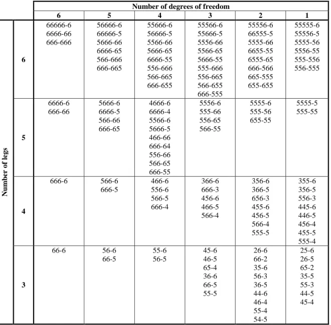
The results are summed up in table 1. In this table, the notation ijkl-mn (with i, j, k, l, m, n = 2 to 6) corresponds to:
- left term: the legs attached to both the fixed base and the moving platform with respectively i, j, k and l joints (passive of active);
- right term: the legs attached to other legs with respectively m and n joints (passive of active). Table 1. Representation of all possible structures with at least one leg attached to two others.
Number of degrees of freedom
6 5 4 3 2 1 Numb er o f leg s 6 66666-6 6666-66 666-666 56666-6 66666-5 5666-66 6666-65 566-666 666-665 55666-6 56666-5 5566-66 5666-65 6666-55 556-666 566-665 666-655 55566-6 55666-5 5556-66 5566-65 5666-55 555-666 556-665 566-655 666-555 55556-6 66555-5 5555-66 6655-55 6555-65 666-566 665-555 655-655 55555-6 55556-5 5555-56 5556-55 555-556 556-555 5 6666-6 666-66 5666-6 6666-5 566-66 666-65 4666-6 6666-4 5566-6 5666-5 466-66 666-64 556-66 566-65 666-55 5556-6 555-66 556-65 566-55 5555-6 555-56 655-55 5555-5 555-55 4 666-6 566-6 666-5 466-6 556-6 566-5 666-4 366-6 666-3 456-6 466-5 566-4 356-6 366-5 656-3 455-6 456-5 566-4 555-5 355-6 356-5 556-3 445-6 446-5 456-4 455-5 555-4 3 66-6 56-6 66-5 55-6 56-5 45-6 46-5 65-4 36-6 66-5 55-5 26-6 66-2 35-6 56-3 36-5 44-6 46-4 55-4 54-5 25-6 26-5 65-2 35-5 55-3 44-5 45-4
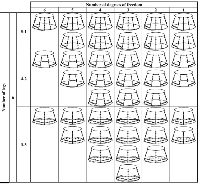
Thus, 118 different kinds of structures can be synthesized. However, such a representation gives no information about the location of the attachment points of the moving legs on the legs fixed to both base and platform. Thus, the results of table 1 can be detailed in table 2 which represents structures with the moving legs located as close as possible of the fixed base. In this table, dark lines represent rigid links and circles pairs with one degree of freedom (active of passive). The notation i-j in the column in left stands for i legs linked to both base and plat-form and j legs attached to two other legs. 118 structures can be depicted in this table, but only the structures with six legs. It is obvious that other architectures are possible, depending on the location of the attachment of the moving legs. Moreover, these 118 possible structures can be also differentiated by the position of the actuat-ed joints.
Table 2. Schematic representation of results of table 1 for manipulators with legs as close as possible from the base.
Number of degrees of freedom
6 5 4 3 2 1 Numb er o f leg s 6 5-1 4-2 3-3
In the following part, we propose to analyze two structures which can be synthesized by our approach and which have interesting characteristics.
3. Description of the proposed structure
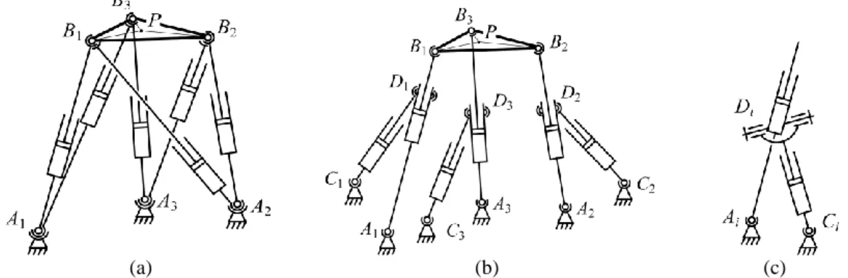
Let us now consider the architecture of the new proposed mechanisms with 6 DOF (Fig. 1). Two cases can be considered in function of the position of the actuators: the actuators are located upon the base (Fig. 1a); the actu-ators are located under the base (Fig. 1b). Both manipulactu-ators are composed of one fixed base A1A2A3 and one
moving platform B1B2B3. The platform is linked to the base by the use of three legs, each of which composed of
one spherical at point Ai, one actuated prismatic pairs AiBi and one spherical joint Bi. Moreover these legs are
linked together by the use of three other linkages composed of one spherical joint Ci, one actuated prismatic pair
CiDj and one spherical joint Dj (j = i + 1 for i = 1, 2, j = 1 for i = 3). It is obvious that such a mechanism
con-tains intern mobility which can be constrained by the use of cardan joints (Fig. 1c). Moreover, as shown on Fig. 1c, the spherical joints can be replaced by three revolute joints. Considering a manipulator composed of 6
pris-matic, 6 spherical and 6 cardan joints, the Grübler formula can give the number of degrees of freedom m of the mechanism:
6
3
4
5
6
5
4
3
n
p
p
p
m
(1)where: n corresponds to the number of body without the base (n = 13); p5 corresponds to the number of pairs
with only one degree of mobility (p5 = 6 prismatic joints); p4 corresponds to the number of pairs with two
de-grees of mobility (p4 = 6 cardan joints); p3 corresponds to the number of pairs with three degree of mobility (p3 =
6 spherical joints).
(a) (b) (c)
Figure. 1. Possible architectures of the new proposed mechanism with three actuators (a) upon the base and (b) under the base, and (c) one possible design for the legs CiDj.
Thus, the simultaneous displacements of actuated joints allow the mechanism having 3 translatory and 3 rotary DOF. We denote: the lengths of the prismatic pairs AiBi as i, (i = 1 to 3); the lengths of the prismatic pairs CiDj
as i+3, (j = i + 1 for i = 1, 2, j = 1 for i = 3). Triangles A1A2A3 and B1B2B3 are considered equilateral. We
con-sider that the controlled point is the point P located at the centre of the triangle B1B2B3. The position of P is
ex-pressed by the vector [x, y, z]T. The base frame is centred at point O located at the centre of triangle A1A2A3
(point O is not represented on Fig. 1). The x0 axis of the base frame is directed along the line A1A2 and the y0 axis
along the line OA3.
The rotations of the platform are denoted , , which can be obtained by expressing the directional cosines in terms of z0-x1-y2 Euler angles , (Fig. 2).
Figure. 2. Description of the chosen Euler angles.
Let us consider inverse geometric analysis. The positions of points Ai, Bi, Ci, Di of the manipulators can be
ex-pressed as (i = 1, 2, 3):
T b i i Rot( , 0) R 0 0 OA z (2) 0 sin cos ) , ( ) , ( ) , ( pl i i pl i R R z y x
0 Rot 1 Rot 2 Rot OB z x y (3) i i i i i l B A OA OC 1 (4)i i i i i l B A OA OD 2 (5)
with Rb = OAi, Rpl = PBi,
i
[
5
/
6
,
/
6
,
/
2
]
, (i = 1, 2, 3) (as said previously, triangles A1A2A3 and B1B2B3 are considered equilateral), l1 =A
iC
i, l2 =A
iD
i, and Rot(, w) the matrix representing the rotation ofangle ( = , and ) around the w-axis of the intermediate frame (w = z0, x1 and y2).
Thus the expressions of the articular coordinates are given by:
i i
T i i i AB AB , for i = 1, 2, 3, (6)
i j
T j i i3
C
D
C
D
, (j = i + 1 for i = 1, 2, j = 1 for i = 3). (7) Let us consider kinematic analysis. The closure equations are represented by the expressions:
i i
T i i i if
0
2
A
B
A
B
for i = 1, 2, 3, (8)
i j
T j i i if
3
0
23
C
D
C
D
, (j = i + 1 for i = 1, 2, j = 1 for i = 3). (9) Differentiating the closure equations with respect to time, one can obtain the following expression (Gosselin and Angeles [5]):
A
v
B
q
0
(10)where:
A and B are two matrices;
i jX
f
A
,
i jf
B
, Xi = (x, y, z, , , ).q
is the vector of the time derivatives of the coordinates of the actuators;q
[
1,
2,
3,
4,
5,
6]
T. v is the vector of the time derivatives of the position of the platform;v
[
x
,
y
,
z
,
,
,
]
T.The vector v can be related to the twist t of the platform expressed in the base frame using a transformation ma-trix D (Merlet [4]):
v
D
t
, with L 0 0 I D 3 3 3 3 3 3 where sin 0 1 cos cos sin 0 cos sin cos 0 L (11)I33 and 033 corresponds to identity and zero matrices of dimensions 33 respectively.
Therefore the Jacobian matrix J relating the twist t of the platform to the velocities of the actuators is given by the relation:
B A D
J 1 (12)
The elements of the matrices A and B depend on the parameters of the mechanisms and on the position of the moving platform.
The next section deals with the comparison between the performances of the proposed manipulators and two other manipulators: the Stewart and Gough platforms.
4. Comparative analysis of performances
In order to appreciate the performances of the new proposed mechanisms, let us compare them with two other manipulators with 6 DOF which are well known, commonly used by manufacturers and also actuated by six prismatic pairs: the Gough platform (Fig. 3a) and the Stewart platform (Fig. 3b). It is obvious that the mecha-nisms presented on Fig. 3 contain intern mobility which can be constrained by the use of cardan or revolute joints (Fig. 3c). Their geometric and kinematic models are well known (see for example the works of Gough [1], Stewart [2], Hunt [3], Merlet [4], Gosselin and Angeles [5], Parenti-Castelli and Innocenti [6]) and, as computing the geometrics and kinematics of these two manipulators is not the main topic of this paper, we will not present them another time.
So, we can consider the following problematic for our comparative analysis: starting from identical components (actuators, base and platform size), what are the arrangements of the actuators which will lead to the greatest workspace taking into consideration: the stroke of the actuators, the displacement of the spherical pairs and the interferences between the elements; the quality of effort transmission in the mechanism.
One industrial version of the Gough platform is the robot FANUC F200. This manipulator is well known for its high payload capacities and its ability to have little deformations under the application of a vertical force. Its approximate geometric parameters are:
- Rpl = 0.2 m and Rb = 0.3 m;
- maximal stroke of the actuators (AiBi)max – (AiBi)min = 0.65 m.
So in order to make a fair comparison, we propose to take into account the following design constraints: - for each kind of manipulator, base and platform have to be identical to those of FANUC F200 robot; - the stroke of the actuators has to be identical and equal to 0.65 m;
- in order to minimize the size of the manipulators, all points located on the base must be comprised on the surface defined by triangle A1A2A3.
So now, let us analyse the size of the workspace taking into account the previous constraints.
(a) (b) (c)
Figure. 3. Schematic representation of (a) the Gough platform and (b) the Stewart platform, and (c) one other possible design for the legs of the Stewart platform.
Let us consider workspace analysis taking into account geometric limitations. The corresponding procedure is very simple. First of all, we discretize the Cartesian space into n points and the orientation space into p configu-rations. The step for the Cartesian space is equal to 0.05 m and for the orientation space to 10 deg for angles comprised between -60 deg and +60 deg for each angle , and . For a point Q to belong to the workspace of the considered manipulator, it should have at least one of the p configurations of the orientation space that valid the geometric limitations. Therefore, this workspace is defined as the maximal workspace (Merlet [4]).
The geometric limitations under study are, for each manipulator:
- the maximal stroke of the actuators has to be identical and equal to 0.65 m;
- in order to avoid interferences between the different elements of the manipulators, the minimal distance between to non secant links has to be equal to 0.1 m, and we consider that the minimal angle between two secant links is equal to 15°. For example, on figure 3c, the angle between links AiDi and CiDi
can-not be inferior to 15°;
- the interval of rotation for the spherical joints has to be comprised between –60 deg and +60 deg. The geometric parameters for the Gough platform are already fixed. For the other manipulators, we chose the geometric parameters that are as close as possible to the parameters of the Gough platform:
- Stewart platform: points C1, C2 and C3 coincide with A2, A3 and A1 respectively, and AiDi = 0.2 m;
- new proposed manipulator, case one (actuators upon the base): l1 = 0.15, l2 = 0.65;
- new proposed manipulator, case two (actuators under the base): l1 = -0.3, l2 = -0.75.
Fig. 4 presents the obtained workspaces. The sizes of the workspace are (m3): Gough platform: 0.719; Stewart platform: 1.749; new proposed manipulator, case one: 1.959; new proposed manipulator, case two: 2.168. The next step of our analysis is the comparison the quality of effort transmission determined by pressure angles existing in the studied mechanisms. These angles can be defined as angles between vectors of forces and transla-tional velocities of points at which the forces are applied. Note, that in Type 2 singular configurations (Gosselin and Angeles [5]) at least one of the pressure angles is equal to 90°.
For any parallel mechanism with passive joints, it is well known that the i-th line of the inverse Jacobian matrix J-1 relating the twist of the platform expressed at point P to the particular velocities (q J1t) corresponds to
the wrench wi applied by the i-th actuator on the platform. For a 6 DOF manipulator, the inverse Jacobian matrix
J-1 can be written as:
J-1 = (w1,. w2, w3, w4, w5, w6)T (13)
(a) Gough platform (b) Stewart platform
(c) New proposed manipulator, case 1 (d) New proposed manipulator, case 2
Figure. 4. Workspaces of the manipulators under study.
connected and the other actuators are fixed. t1 is the twist reciprocal to the wrenches w2 to w6 applied on the
plat-form by the actuators 2 to 6. Therefore we can have the five following relations:
iz z iy y ix x iz z iy y ix x
F
v
F
v
F
M
M
M
v
1 1 1 1 1 10
, (i = 2 to 6) (14) where: VP = [v1x, v1y, v1z] Trepresent the translational velocities of point P of the platform along the axes x, y and z re-spectively;
1
Ω
1x, 1y, 1z]T
represents the rotational velocities of the platform around the axes x, y and z respectively;
Fix, Fiy, Fiz represent the forces applied on the platform by the i-th actuator along the axes x, y and z respectively;
Mix, Miy, Miz represent the moments applied at point P on the platform by the i-th actuator around the axes x, y
and z respectively.
Fixing the value of v1x to 1, one can determinate the expressions of the other terms of the twist t1:
x 1F
N
t
1
1 ,
z y x z y z y x z yM
M
M
F
F
M
M
M
F
F
6 6 6 6 6 2 2 2 2 2
N
,F
x
[
F
2x,
F
3x,
F
4x,
F
5x,
F
6x]
T (15) For each of the four manipulators, the wrench applied by actuator 1 on the point B1 of the platform is a pureforce F1. The translational velocity VB1 of point B1 can be deduced from the expressionVB1VPB1PΩ1.
The terms of this expression are detailed above. Therefore, the pressure angle 1 can be determined as:
B 1 1 B 1 1 V F V FT 1 1 cos (16)
Please note that the pressure angle is an indicator of the power transmitted by the actuator 1 to the platform, which can be written as:
P
F
1TV
B1
F
1V
B1cos
1.These pressure angles can be calculated in a similar way for the Gough and Stewart platforms and for actuators 1 to 3 of the new mechanisms. However, for actuators 4 to 6 of the new manipulators, the way to compute the pressure angles is a bit different. Without loss of generality, let us consider the link C1D2 (Fig. 1a). Basing on
relation, equivalent to (15), it is possible to compute the twist t4 of the platform when actuator 4 is disconnected
and the others are fixed, and as a result, the translational velocities VC1 and VD2: VC1=(l1/1)VB1, VD2=(l2/2)VB2.
The power transmitted by the actuator to the mechanism can be written under the form:
D2 C 1
4 D2C 14
V
V
F
V
F
T
T
P
, where F4 represents the effort applied by the actuators on links A1B1 and A2B2, VD2C1 represents the relative velocity of the point D2 from the point C1. Therefore, one can define apres-sure angle 4: D2 C 1 4 D2 C 1 4 V F V FT 1 4 cos (17)
The same approach can be used in order to determine the pressure angles of actuators 5 and 6.
Thus, we can now analyse the workspace of the studied manipulators taking into account the maximal value of the pressure angles of the mechanisms. We consider that the maximal admissible value for the pressure angle is 82°. For one point of the workspace, if there exists at least one configuration of the orientation space for which the pressure angle is inferior to 82°, so this point belongs to the workspace of the robot. Therefore, we can obtain new results about the workspace of our manipulators. The sizes of the workspace are (m3): Gough platform: 0.719; Stewart platform: 1.727; new proposed manipulator, case one: 1.952; new proposed manipulator, case two: 2.154.The new results are similar to those obtained previously.
7. Conclusion.
Thus, in this article, the parallel-cross manipulators are represented as well as their classification. The compari-son analysis executed for the new manipulators and well known parallel manipulators taking into account geo-metric limitations and admissible pressure angles allows to conclude, that the workspace of the new manipula-tors is not less than this of well known parallel manipulamanipula-tors.
References.
[1] Gough, V.E., Contribution to Discussion to Papers on Research in Automobile Stability and Control and in Tyre Performance by Cornell Staff, Proceedings of Autom. Div. Inst. Mech. Eng., 1956/57, pp. 392-396. [2] Stewart, D. A., Platform with Six Degrees of Freedom, Proceedings of the Institution of Mechanical
Engi-neers. London. 1965. Vol. 180, Part 1, No 15, 1965, pp. 371-386.
[3] Hunt, K., Structural Kinematics of In-Parallel-Actuated Robot Arms, ASME Journal of Mechanisms,
Trans-missions, and Automation in Design, Vol. 105, No 4, 1983, pp. 705-712.
[4] Merlet, J.P., Parallel Robots. Kluwer Academic Publishers, 2000. 372 p.
[5] Gosselin, C.M., Angeles, J., Singularity Analysis of Closed Loop Kinematic Chains, IEEE Trans. on Robotics
and Automation, No 6(3), 1990, pp. 281-290.
[6] Parenti-Castelli, V., Innocenti, C., Direct Displacement Analysis for Some Classes of Spatial Parallel Mecha-nisms, Proceedings, VIII CISM-IFToMM Symposium on Theory and Practice of Robots and Manipulators, Cracow, Poland, 1990, pp. 123-130.
[7] Glazunov, V.A., Briot, S., Arakelyan, V., Gruntovich, M.M., and Ngyuen Minh Thanh, Development of ma-nipulators with a parallel-cross structure, Journal of Machinery Manufacture and Reliability, Allerton Press Inc., No 2, 2008, pp. 85-91.
[8] Sutherland, G., Roth, B., A transmission index for spatial mechanisms, Transactions of the ASME. Journal of
Engineering for Industry, Vol. 95, 1973, pp. 589-597.
[9] Lin, C.-C., Chang, W.-T., The force transmissivity index of planar linkage mechanisms, Mechanism and
Ma-chine Theory, Vol. 37, 2002, pp. 1465-1485.
[10] Arakelian, V., Briot, S., Glazunov, V., Increase of singularity-free zones in the workspace of parallel manipu-lators using mechanisms of variable structure, Mechanism and Machine Theory, Vol. 43, No 9, 2008, pp. 1129-1140.