The Annular Groove Phase Mask coronagraph: an
achromatic optical vortex
Dimitri Mawet
a, Pierre Riaud
d, Charles Hanot
a, Denis Vandormael
c,
J´erome Loicq
c, Jacques Baudrand
d, Jean Surdej
aand Serge Habraken
b,c aInstitut d’Astrophysique et de G´eophysique de Li`ege (IAGL), University of Li`ege,
17 All´ee du 6 Aoˆut, 4000 Sart Tilman, Belgium;
bHOLOLAB, Department of physics, University of Li`ege,
17 All´ee du 6 Aoˆut, 4000 Sart Tilman, Belgium;
c
Centre Spatial de Li`ege (CSL), Av. du Pr´e-Aily, 4031 Angleur, Belgium;
dObservatory of Paris-Meudon, 5 Place Jules Janssen, F-92195 Meudon, France.
ABSTRACT
The Annular Groove Phase Mask coronagraph (AGPM) is an intrinsically achromatic vectorial vortex. It consists of integrated subwavelength optical elements whose space-variant polarization properties can be engineered and optimized to synthesize one of the theoretically most efficient coronagraphs. This paper briefly recalls the principles of the AGPM, presents the benefit of its implementation inside a polarimetric differential imager, realistic numerical simulations assessing its performances, as well as the current status of the near-infrared and visible prototype manufacturing operations.
Keywords: coronagraphy, optical vortices, subwavelength optical elements
1. INTRODUCTION
Optical vortices have recently gained interest in the coronagraphists community.1–6 Such attraction is
comprehen-sible since they present many advantages over other concepts of coronagraphs like for example, the conjunction of high rejection ratios, small inner working angle (IWA), full discovery space, high throughput, etc. In the framework of ground-based coronagraphy for second-generation instrumentation, they are foreseen to advan-tageously replace classical Lyot coronagraphs, and even more recent coronagraphs such as the four-quadrant phase-mask7 coronagraph (FQPM). For coronagraphic space-based telescope projects aimed at characterizing
extrasolar planets down to Earth-size objects (Terrestrial Planet Finder-Coronagraph8 and precursor mission
projects such as the Super Earth Explorer-Coronagraphic Off Axis Space Telescope9), where the detectivity
constraints are dramatically emphasized, optical vortices represent a competitive approach. Nevertheless, two major problems are to be solved before seriously considering the implementation of optical vortices into these ambitious space observatories. First of all, as optical vortices are phase masks, one has to find a way to effi-ciently achromatize them, i.e. making them keeping their high rejection ratios over wavelength ranges equivalent to usual astrophysical filters (bandwidth of about 20%). Second, their sensitivity to low-order aberrations has to be mitigated and maintained below an acceptable level for the telescope optical finish, assembly, pointing and stability constraints to remain in manageable margins. This issue also relates to the sensitivity to stellar angular diameter which is known to dramatically affect small inner working angle coronagraphs in general.6
Further author information: (Send correspondence to D. Mawet) D. Mawet: E-mail: mawet@astro.ulg.ac.be, Telephone: +32 (0)4 3669757
H
L
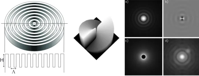
Figure 1. Left: concentric space-variant implementation of subwavelength grating leading to the AGPM. Middle: Pan-charatnam2 4π phase ramp of the AGPM leading to the l
p= 2 vortex generation. Right panel: a) Polychromatic Airy
pattern, b) focal plane phase visualization (after the AGPM), c) relayed pupil plane, where we notice the perfect symmetry of the rejection in an annular way, d) final coronagraphic image revealing the 15 mag fainter simulated companion. All images are displayed in non linear scale.
2. THE ANNULAR GROOVE PHASE MASK CORONAGRAPH
The annular groove phase mask coronagraph2 consists of a space-variant subwavelength grating synthesizing a
vectorial optical vortex of topological charge lp= 2 (Fig. 1), analytically leading to a total starlight rejection in
the theoretically perfect case2, 3 (perfect component, no wavefront errors, unobscured pupil, perfect centering of
the star on the optical axis,...). It is to be emphasized that the AGPM nominally works in unpolarized natural light. In the real world however, nothing is perfect and the component itself is hampered by leaks. Subwavelength gratings are known to synthesize artificial birefringent elements but they certainly are not perfect vectorial phase shifters (vectorial means that the phase shift occurs between orthogonal polarization components, like a classical waveplate retarder) and induce differential losses.10 The latter can be quantified by rigorous diffraction analysis
(e.g., the rigorous coupled wave analysis,11 or RCWA), leading to a thorough description of the component by
the following Jones matrix in the helical (circular polarization) basis∗:
AGP M (λ) =1 2(ηT E(λ) + ηT M(λ)e i∆φ(λ)) · 1 0 0 1 ¸ +1 2(ηT E(λ) − ηT M(λ)e i∆φ(λ)) · 0 ei2θ e−i2θ 0 ¸ (2) Where ηT E(λ) and ηT M(λ) are the wavelength-dependent diffraction efficiencies of the subwavelength grating
in the zeroth order for the orthogonal polarizations TE (transverse electric, or s) and TM (transverse magnetic, or p) and ∆φ(λ), the phase shift (retardance) between them. Ideally, ηT E = ηT M = 1 and ∆φ = π whatever
the wavelength λ (achromaticity Holy Grail) so that the incoming circular polarization is reversed (left-handed becomes right-handed and vice-versa) and affected by a pure optical vortex ei2θ, leading to a perfect attenuation
of the on-axis coherent starlight.2 In practice, the inevitable departure from this nominal case is proportional to
the working bandwidth. Then, a residual of weight 1
2(ηT E(λ) + ηT M(λ)ei∆φ(λ)) appears and contaminates the
∗In the circular (helical) polarization basis, the unitary polarization vectors are either the right-handed one [10] or the
left-handed one [01]. The helical-basis transformation matrix U that allows switching between the classical linear and helical basis is defined by
U = √1 2 · 1 i 1 −i ¸ (1)
PBS
Mod
AGPM
QWP P
detector
disperser
lenslet
array
Arm 2
Sensing
LS
QWP
Arm 1
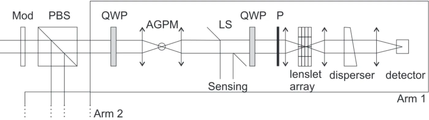
Figure 2. Optical schematic of the AGPM differential polarimetric spectro-imager instrumental concept. The beam is first slowly modulated by a variable retarder (LCVR, FLC or PEM, or simply a rotating halfwave plate), then split by a polarizing beamsplitter (PBS) into two equivalent arms of orthogonal linear polarizations (Arm 1 and 2). QWP are achromatic quarterwave plates that convert the linear polarization to the circular one to efficiently feed the AGPM coronagraph. LS stands for Lyot stop, which is a diaphragm reflecting the residual starlight to a sensing unit (star fine centering on the coronagraph). The Integral Field Spectrograph unit is based on a TIGER-type lenslet-array for instance.
pure vortex. The key point is that this residual, bearing all the component imperfections has the same polar-ization state as the incoming one, where the vortex has been transferred in the reverse polarpolar-ization. Therefore, appropriate filtering at the input and the output of the component should remove these imperfections and lead to improved performances with respect to the natural unpolarized light case. The filtering consists of a circular polarizer before the coronagraph and the opposite circular analyzer after it. As the component is perfectly symmetric in circular polarization, the system can be switched between both circular orthogonal polarizations, so that in the state 1 (resp. state 2), we have a right-handed (resp. left-handed) polarization input filter and a left-handed (resp. right-handed) output one.
3. THE AGPM AND DIFFERENTIAL IMAGING
Speckle subtraction/calibration techniques such as Spectral Differential Imaging12 (SDI) and Polarimetric
Dif-ferential Imaging13 (PDI) have been in competition with coronagraphy for a long time. It is only recently that
second generation extreme adaptive optics (XAO) instruments have brought both concepts to work together but always in cascade or separately (e.g. Gemini Planet Imager,14GPI, and the Very Large Telescope’s Planet
Finder,15 SPHERE). The AGPM properties allows us to propose combining the three instrumental approaches
in a single one: a coronagraphic polarimeter. With a classical Lyot amplitude coronagraph, the spectro-polarimeter can be considered independently and implemented downstream the coronagraph (like on GPI). With a phase-mask coronagraph such as the AGPM, which intrinsically allows accessing much smaller IWA, this is not possible due to the polarization properties of the coronagraph. It must therefore be implemented inside the spectro-polarimeter. If this implementation is conducted wisely, each subsystem can take advantage of the other, as we will demonstrate here below. The key point is that the bandwidth can seriously be enlarged without sac-rificing the performances. Indeed, the implementation of the AGPM in the polarization-filtered system provides a significant gain in rejection allowing an “ultimate” achromatization.
This property makes the AGPM a coronagraph especially suited to differential imaging provided that it is properly implemented inside the polarimeter. Its symmetry also allows for alternate switching between two orthogonal polarization states that are linear at the input. In conclusion, a polarimetric system which converts the polarization signal with a polarization modulator into a temporal intensity modulation can be designed to accommodate the AGPM coronagraph, leading to a symbiosis (both concepts can take advantage of the other) and substantial performance improvements. One key point is that in space, the polarimetric modulation can be much slower than for ground-based polarimeters such as ZIMPOL.13 Fig. 2 presents a preliminary optical
4. THEORETICAL ANALYSIS
Let us now demonstrate in detail the gain provided by the incorporation of the AGPM in a polarimeter which is internally working in a helical basis (note here that the polarization measurement/calibration still externally occurs on the linear polarization). For that, we will use the Jones formalism. Doing this, let us detail the Jones expression of the polarization components displayed in Fig. 2:
P BSArm1 = · 1 − 1/ER 0 0 1/ER ¸ (3) PArm1= · 1/ER 0 0 1 − 1/ER ¸ (4) QW PArm1 = · sQW P× e−i∆φQW P 0 0 pQW P× e+i∆φQW P ¸ (5) M (θ) = · cos θ − sin θ sin θ cos θ ¸ (6) where ER is the extinction ratio of the polarizing beamsplitter (PBS) and polarizer (P), sQW P and pQW P
the efficiency of the quarterwave plate in transmitting the s and p polarization components (ideally s = p = 1), ∆φQW P the actual retardance of the quarterwave plate, which should be π/2 rad. M is the rotation matrix (the
quarterwave plate before and after the coronagraph are rotated by 45◦ with respect to the PBS and polarizer
while being perpendicular). We will also use the AGPM Jones matrix given here above in its natural helical basis, which can be related to the linear basis thanks to the U matrix.
The final expression giving the output polarization state in the Arm 1 of the optical scheme of Fig. 2, considering the main s = [1 0]T component, is
Os
Arm1 = P ∗ (M0∗ QW PArm1∗ M0−1) ∗ (U−1∗ AGP M ∗ U ) ∗ (M ∗ QW PArm1∗ M−1) ∗ P BSArm1∗ [1 0]T (7)
whereas the leakage due to the undesired p = [0 1]T component is
OArm1p = P ∗ (M0∗ QW P
Arm1∗ M0−1) ∗ (U−1∗ AGP M ∗ U ) ∗ (M ∗ QW PArm1∗ M−1) ∗ P BSArm1∗ [0 1]T (8)
Let us now put some figures on these formulae. We will assume that the extinction ratio of the polarizers is ER = 106 (103 in amplitude), corresponding to classical commercial component specs. As far as the AGPM vectorial
vortex coronagraph is concerned, thorough optimization of the subwavelength grating structural parameters (period, feature line and thickness) gives a mean theoretical rejection performance of ∼ 500 in natural unpolarized light (we have assumed the worst case over the considered wavelength range, ηT E = 0.78 ; ηT M = 0.82 and
∆φ = π ± 0.1 rad) in the huge bandwidth spanning from 450 to 800 nm. Concerning the achromatic quarterwave plates, which are critical components here, we took sensible values for achromatic Quartz-M gF2 plates sold by
traditional manufacturers, i.e. a retardance error of 0.1 PTV rad with respect to π/2.
Taking these hypothesis into account gives a total attenuation of a few 10−8(see Table 1 for other numerical
examples). This value does not correspond to the contrast level but to the expected total attenuation of the starlight integrated over the whole discovery space (starting at very small IWA), before any speckle subtrac-tion/calibration. Neglecting wavefront errors of the optics (see the following section), these conservative (we have assumed commercial component specs) calculations show that an in-line polarimeter and the AGPM coro-nagraph are well suited to work together. Indeed, the performance of the AGPM has been boosted by several orders of magnitude, allowing its use over huge bandwidths (we can indeed speak of ultimate achromatization) while the differential polarimetric imaging system has been fed with a much lowered starlight level, reducing the photon noise to the minimum.
Table 1. Theoretical results in terms of total attenuation and contrast of the AGPM with polarization filtering, neglecting WFE issues and therefore speckle subtraction/calibration potential gain.
AGPM natural light Polarizer ER QWP accuracy Total attenuation integrated Broadband contrast broadband rejection over the whole at 1.5 λ/d
(R = λ/∆λ ≈ 2) discovery space
500 104 0.5 rad PTV 5 × 10⁻⁵ ∼ 10−6
500 104 0.1 rad PTV 5 × 10⁻⁷ ∼ 10−8
500 106 0.1 rad PTV 5 × 10⁻⁸ ∼ 10−9
5. NUMERICAL SIMULATIONS
In practice, the polarization filtering principle is not perfect and we must account for the filtering component imperfections at the same level as upstream optics wavefront errors (WFE). These are of three types:
- polarization errors, i.e., finite extinction ratio for polarizers and retardance errors for waveplates; - WFE of polarization components, which are critical for those upstream the coronagraph
- straylight issues (ghosts), mostly due to the polarization components before the coronagraph.
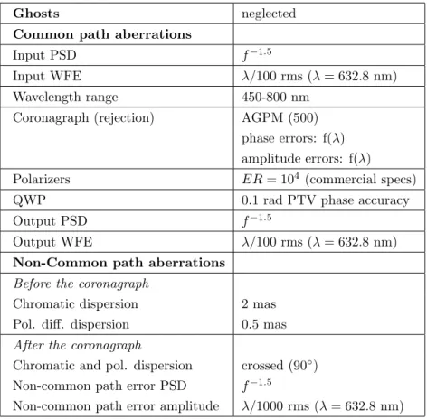
Table 2. Hypothesis of the coronagraphic numerical simulation. PSD stands for Power Spectrum Density.
Ghosts neglected
Common path aberrations
Input PSD f−1.5
Input WFE λ/100 rms (λ = 632.8 nm)
Wavelength range 450-800 nm Coronagraph (rejection) AGPM (500)
phase errors: f(λ) amplitude errors: f(λ) Polarizers ER = 104 (commercial specs)
QWP 0.1 rad PTV phase accuracy Output PSD f−1.5
Output WFE λ/100 rms (λ = 632.8 nm)
Non-Common path aberrations
Before the coronagraph
Chromatic dispersion 2 mas Pol. diff. dispersion 0.5 mas
After the coronagraph
Chromatic and pol. dispersion crossed (90◦)
Non-common path error PSD f−1.5
Non-common path error amplitude λ/1000 rms (λ = 632.8 nm)
We have already taken into account polarization element errors. Ghost problems, mostly due to the polarization components before the coronagraph are also to be minimized. Classical solutions are state-of-the-art antireflective
1 2 3 4 5 6 7 10-12 10-10 10-8 10-6 10-4 10-2 100 Angular separation (l/d) Contrast
Figure 3. Coronagraphic profiles generated by a numerical simulation taking into account the hypothesis mentioned in Table 2. Finely-dotted curve: polychromatic Airy profile (450-800 nm). Dashed curve: AGPM coronagraphic profile in unpolarized broadband (50%-bandwidth) light. Dash-dotted curve: the same after polarization filtering. Plain curve: contrast after polarimetric speckle subtraction/calibration.
treatments and proper implementation of the components. For instance, we could use the “wedging” method which has been developed in infrared nulling interferometry for the same purpose. The stray light dumping should not degrade polarization and should not introduce too much spectral and polarization dispersions. It must stay in the 1 mas centering range (a slight dispersion will be considered in the numerical simulation presented below). WFE upstream the coronagraphs, resulting from the telescope optical assembly, relay optics and polarization components, are critical and often necessitate active and/or passive correction systems.
The following numerical simulation, which has been realized in the framework of the SEE-COAST space telescope project, is based on hypothesis as realistic as possible, which are summarized in Table 2. The simulation is rather complex and uses three different codes: to get the AGPM micro-component optical characteristics in terms of phase and amplitude, a rigorous diffraction code (RCWA) was used; the general polarization behavior was interpreted by a code based on the Jones formalism (see the previous section); the Fraunhofer diffraction was implemented by a traditional coronagraphic code using Fourier transforms.
The results of the simulation is displayed in Fig. 3 in the form of coronagraphic profiles in the final detection plane of the instrument. Note that the rough attenuation without polarization filtering is of about 500. The filter-ing allows reachfilter-ing the WFE-limited noise floor (speckle level). Speckle calibration via polarimetric subtraction allows reaching the floor limited by non-common path aberrations between the 2 polarimetric channels.
6. NOTE ABOUT SENSITIVITY TO TIP-TILT AND STELLAR DIAMETER
Sensitivity to tip-tilt and stellar diameter of the AGPM basically grows as θ2. Speckle calibration thanks toLeft: SiO2 AGPM photolithographic masks imprinted by direct writing laser (courtesy of CSL). Right: SEM
pictures of the central part of the component (courtesy of CSL).
to jitter for instance may anyway require to increase the power of the sensitivity to this low-order aberration at least. For that, we must increase the topological charge of the vortex because the dependency θn to the
aberration directly scales with the vortex topological charge,2 n = l
p. Two solutions exist. The first one is
to implement the space-variant grating in another surface pattern intrinsically generating a higher topological charge.2, 16 The second one allows keeping the AGPM circularly symmetric geometry which is more convenient
to manufacture. The principle is to stack two AGPM with a halfwave plate between them (unlike scalar vortices, the topological charges of vectorial vortices do not simply add). Doing so, the AGPM topological charge is easily incremented from lp= 2 to lp= 4: · 0 ei2θ e−i2θ 0 ¸ · 0 −i −i 0 ¸ · 0 ei2θ e−i2θ 0 ¸ = −i · 0 ei4θ e−i4θ 0 ¸ (9) This can be iterated to provide any even topological charge and thus sensitivity to low-order aberration. Note that the stack can be integrated within a few microns on top of a substrate thanks to the subwavelength grating technology.
7. PROTOTYPING
Vectorial vortices up to topological charges of 4 based on subwavelength optical elements are extensively studied by Erez Hasmans group at Israel Institute of Technology, mainly for CO2laser applications16(at 10.6 µm). The
micro-components manufactured for their purposes are mainly integrated on AsGa substrates.
As far as the AGPM is concerned, the “Centre Spatial de Li`ege” (CSL) has begun prototype manufacturing on SiO2 samples for the near-infrared (H-band, around 1.65 µm). The subsequent structure period is around 1
µm, while its thickness is around 10 µm. The most appropriate method to manufacture the micro pattern is
based on photolithography and dry etching processes. The first one is necessary for masking the parts of the substrates to be protected during the etching step. Direct writing laser (DWL) or mask exposure techniques are directly applicable. We have chosen to use the DWL tool available at CSL to imprint the AGPM lithographic mask. Results after process optimization were encouraging (Fig. 7). The difficulty was to imprint the circular binary feature while mitigating aliasing effects. Then, the surface pattern serves as a lithographic mask for the subsequent reactive plasma etching process. Reactive plasma beam etching (RPBE) makes use of both the ballistic effect and chemical reactivity of a beam of reactive ions to remove or create structures into a substrate. The various parameters (gas melanges, beam energy, beam incidence...) characterizing the etching process are optimized for the transfer into various materials. For SiO2, the gas is based on a CHF3 chemistry. The interest
of such a technique comes particularly from its high selectivity, the potential to efficiently etch one material and not another coexisting one. RPBE is widely used in the fabrication of micro-optical elements, micro-sensors and other micro-machines. The next step under optimization is the deep etching of the pattern into the SiO2
substrate, indeed, the goal aspect ratio is ∼ 20, quite a challenging value.
Making subwavelength gratings for the visible wavelength range is not trivial. The period of the grating must absolutely be smaller than λ/n, n being the index of refraction of the chosen substrate material. We therefore have to deal with periods in the 300 to 400 nm range according to the material. Controlling the micro-structure at such scales is challenging but feasible using for instance nano-imprint lithography techniques. In this context, let us cite the work of NanoOpto17for optical pickup units. NanoOpto indeed proposed, manufactured and tested
(now commercializes) achromatic subwavelength grating waveplates for the visible. Converting the performance of their manufactured components in terms of nulling efficiency would lead to a 1000 rejection ratio over a bandwidth of more than 20 % in natural light which is sufficient for the proposed concept. There is still room for improvement. NanoOpto has been contacted to make AGPM prototypes.
8. CONCLUSION
In this paper, we have presented the AGPM as a very performing optical vortex coronagraph. We chose to implement the vortex using space-variant subwavelength optical elements, which are very flexible in terms of design, allowing broadband performances over any wavelength range, from the optical to the infrared. The AGPM is achromatic and therefore particularly suited to spectral differential imaging. Its polarization properties also allows a symbiosis with polarimetric differential imagers. The fabrication, based on micro-electronic technologies, is quite challenging but the feasibility has previously been demonstrated. Prototypes are under manufacturing and should be tested in a near future.
ACKNOWLEDGMENTS
The authors acknowledge the financial support of the Belgian FNRS.REFERENCES
1. G. Swartzlander, “Peering into darkness with a vortex spatial filter,” Optics Letters 26, pp. 497–499, 2001. 2. D. Mawet, P. Riaud, O. Absil, and J. Surdej, “Annular Groove Phase Mask Coronagraph,” ApJ 633,
pp. 1191–1200, Nov. 2005.
3. G. Foo, D. M. Palacios, and G. A. Swartzlander, “Optical vortex coronagraph,” Optics Letters 30, pp. 3308– 3310, Dec. 2005.
4. G. Swartzlander, G. Biener, V. Kleiner, and E. Hasman, “Broadband nulling of a vortex phase mask,”
Optics Letters 30, pp. 2876–2878, 2005.
5. D. M. Palacios, “An optical vortex coronagraph,” in Techniques and Instrumentation for Detection of
Exoplanets II. Edited by Coulter, Daniel R. Proceedings of the SPIE, Volume 5905, pp. 196-205 (2005).,
D. R. Coulter, ed., pp. 196–205, Aug. 2005.
6. O. Guyon, E. A. Pluzhnik, M. J. Kuchner, B. Collins, and S. T. Ridgway, “Theoretical Limits on Extrasolar Terrestrial Planet Detection with Coronagraphs,” ApJS 167, pp. 81–99, Nov. 2006.
7. D. Rouan, P. Riaud, A. Boccaletti, Y. Cl´enet, and A. Labeyrie, “The Four-Quadrant Phase-Mask Corona-graph. I. Principle,” PASP 112, pp. 1479–1486, Nov. 2000.
8. S. Shaklan and M. Levine, “Terrestrial Planet Finder Coronagraph Mission Overview,” in Proceedings of
the conference In the Spirit of Bernard Lyot: The Direct Detection of Planets and Circumstellar Disks in the 21st Century. June 04 - 08, 2007. University of California, Berkeley, CA, USA. Edited by Paul Kalas.,
P. Kalas, ed., June 2007.
9. J. Schneider, A. Boccaletti, P. Riaud, G. Tinetti, and The See Coast Team, “The Super-Earth Explorer,” in
Proceedings of the conference In the Spirit of Bernard Lyot: The Direct Detection of Planets and Circum-stellar Disks in the 21st Century. June 04 - 08, 2007. University of California, Berkeley, CA, USA. Edited by Paul Kalas., P. Kalas, ed., June 2007.
10. D. Mawet, P. Riaud, J. Surdej, and J. Baudrand, “Subwavelength surface-relief gratings for stellar coron-agraphy,” Applied Optics 44, pp. 7313–7321, 2005.
11. M. Moharam and T. Gaylord, “Diffraction analysis of dielectric surface-relief gratings,” JOSA 72, pp. 1385– 1392, 1982.
12. C. Marois, R. Doyon, D. Nadeau, R. Racine, M. Riopel, P. Vall´ee, and D. Lafreni`ere, “TRIDENT: An Infrared Differential Imaging Camera Optimized for the Detection of Methanated Substellar Companions,”
PASP 117, pp. 745–756, July 2005.
13. H. M. Schmid, J.-L. Beuzit, M. Feldt, D. Gisler, R. Gratton, T. Henning, F. Joos, M. Kasper, R. Lenzen, D. Mouillet, C. Moutou, A. Quirrenbach, D. M. Stam, C. Thalmann, J. Tinbergen, C. Verinaud, R. Waters, and R. Wolstencroft, “Search and investigation of extra-solar planets with polarimetry,” in IAU Colloq. 200:
Direct Imaging of Exoplanets: Science and Techniques, C. Aime and F. Vakili, eds., pp. 165–170, 2006.
14. B. Macintosh, J. Graham, D. Palmer, R. Doyon, D. Gavel, J. Larkin, B. Oppenheimer, L. Saddlemyer, J. K. Wallace, B. Bauman, J. Evans, D. Erikson, K. Morzinski, D. Phillion, L. Poyneer, A. Sivaramakrishnan, R. Soummer, S. Thibault, and J.-P. Veran, “The Gemini Planet Imager,” in Advances in Adaptive Optics
II. Edited by Ellerbroek, Brent L.; Bonaccini Calia, Domenico. Proceedings of the SPIE, Volume 6272, pp. 62720L (2006)., Presented at the Society of Photo-Optical Instrumentation Engineers (SPIE) Conference
6272, July 2006.
15. J.-L. Beuzit, M. Feldt, K. Dohlen, D. Mouillet, P. Puget, J. Antici, A. Baruffolo, P. Baudoz, A. Berton, A. Boccaletti, M. Carbillet, J. Charton, R. Claudi, M. Downing, P. Feautrier, E. Fedrigo, T. Fusco, R. Grat-ton, N. Hubin, M. Kasper, M. Langlois, C. Moutou, L. Mugnier, J. Pragt, P. Rabou, M. Saisse, H. M. Schmid, E. Stadler, M. Turrato, S. Udry, R. Waters, and F. Wildi, “SPHERE: A ’Planet Finder’ Instrument for the VLT,” The Messenger 125, pp. 29–+, Sept. 2006.
16. A. Niv, G. Biener, V. Kleiner, and E. Hasman, “Spiral phase elements obtained by use of discrete space-variant subwavelength gratings,” Optics Communications 251, pp. 306–314, 2005.
17. X. Deng, F. Liu, J. Wang, P. J. Sciortino, L. Chen, and X. Liu, “Achromatic wave plates for optical pickup units fabricated by use of imprint lithography,” Optics Letters 30, pp. 2614–2616, 2005.