Université Ahmed Draia - Adrar Faculté des Sciences et de la Technologie Département des Mathématiques et Informatique
A Thesis Presented to Fulfill the Partial Requirement
for Master’s Degree
in Computer Science
Option :
Network and Intelligent Systems
Title
Hybridizing PEGASIS protocol with LEACH-1R
using Inter-Cluster and Intra-Cluster Chains
Prepared by
Imane BOULHARES
Supervised by
Dr. Mohammed OMARI
Abstract
Wireless Sensor Networks (WSNs) consist of small nodes with sensing, computation, and wireless communications capabilities. These sensor nodes are inexpensive portable devices with limited processing power and energy resources. Routing is one of the new key technology which has become a hot research nowadays since the applications of WSNs are growing everywhere. Hierarchical routing in wireless sensor networks (WSNs) is a very important topic that has been attracting the research community in the last decade. Typical hierarchical routing is called clustering routing, in which the network is divided into multiple clusters. Recently, some types of atypical hierarchical routing arise, including chain-based, tree-chain-based, grid-based routing, and area-based routing. In our work, we proposed a set of hierarchical hybrid protocols between clustering-based LEACH-1R protocol and chain-based PEGASIS protocol. Where we aim to enhance the lifetime of the network. For experimental results, we implemented the existing LEACH-1R and PEGASIS protocols as well as four hybridized protocols using the MATLAB environment in order to compare them vis-à-vis the energy consumption and the lifetime of the network. Experimental results showed that hybridization that implements cluster external chain overcomes other hybrid models as well as the original protocols in terms of maximizing the network lifetime.
III
Dedicates
First of all, my thanks go to Allah our Almighty Creator
and to
Our great teacher the messenger Mohammed “peace be
upon him”.
I dedicate this thesis to my dear family who give me all
help and never forget me in their prayers.
A big gratitude to my parents may Allah bless them.
A special dedicate to my beloved sisters.
I send a big greeting for all my close friends and
neighbors, to people who never forget me and all the ones
in my life who touched my hearts.
Greetings and appreciations to all those who are asking for
science and never get tired of seeking knowledge.
I dedicate this research to the University Ahmed Draya, to
the MI department, my professors, my classmates and the
working agents.
IV
ACKNOWLEGMENTS
In the Name of Allah, the Most Merciful, the Most
Compassionate all praise be to Allah, the Lord of
the worlds; and Prayers and peace be upon Mohamed
His servant and messenger.
First and foremost, I must acknowledge my limitless
thanks to Allah, the Magnificent; the
Ever-Thankful, for His help and bless. I am totally sure that
this work would have never become completed, without
His guidance.
I owe profound gratitude to my supervisor Dr.
Mohammed Omari for his guidance and his patience.
I also would like to express my grateful thanks to my
family for their generous support they provided me
throughout my entire life. Because of their
unconditional love and prayers, I have the chance to
complete this thesis.
Thank you for all my professors and my close friends.
Thank you.
Table of Content
Abstract………..I
Dedicates………...II Acknowledgements……….III
Table of Contents………..…………..IV
List of Figures……….….VIII List of Tables……….…..X
List of abbreviation………XI
General introduction…...……….1
Chapter 01: overview on wireless sensor networks 1. Background………...…………3
2. Ad hoc network………...………..3
3. wireless sensor networks………...…3
3.1.Definition………..…..3
3.2.Types of WSNs………..….4
3.3.Factors influencing wireless sensor network design………..….5
3.4.Applications domains………..…7
3.4.1. Military applications………...8
3.4.2. Environment Observation………...8
3.4.3. Precision Agriculture………..9
3.4.5. Habitat Monitoring………....10
3.4.6. Home Automation……….10
3.4.7. Other Commercial Applications………...11
4. Structure of wireless sensor networks……….…11
4.1. Sensor node structure………...11
4.1.1. The sensing unit………...12
4.1.2. The processing unit……….….12
4.1.3. The communication unit……..………12
4.1.4. The power unit………12
4.1.5. The Memory/storage unit……….12
4.2. Base station……….12
4.3. Data transmission………13
5. Data aggregation in WSNs……….13
5.1.Classification of Data Aggregation Mechanisms……….13
5.1.1. Structure-Free Data Aggregation……….…14
5.1.2. Structure-Based Data Aggregation………..…14
5.1.3. Hybrid structure Data Aggregation………..…14
6. Conclusion………..…14
Chapter 02: Hierarchical routing in wireless sensor networks 1. Background………...………..16
2. Routing in wireless sensor networks………...16
3. Classification of routing protocols in WSNs………..16
3.1.Initiator of Communication Based Routing Protocol………17
3.2.Path establishment Based Routing Protocols………18
3.2.1. Proactive Protocols………...18
3.2.2. Reactive Protocols……….18
3.2.3. Hybrid Protocols………...18
3.3.Network Structure……….18
3.3.2. Hierarchical Routing……….19
3.3.3. Location-based………..19
3.4.Protocol Operation………19
3.4.1. Multipath-Based Routing………..19
3.4.2. Query-Based Routing………20
3.4.3. Negotiation-Based Routing Protocols………...20
3.4.4. QoS-Based Routing………...20
3.4.5. Non-coherent and Coherent Data-Processing Based Routing……….21
3.5.Next-Hop Selection Based Routing Protocols………..21
3.5.1. Content-based routing protocols………...21
3.5.2. Probabilistic routing protocols………..21
3.5.3. Location-based routing protocols……….21
3.5.4. Hierarchical-based routing protocols………22
3.5.5. Broadcast-based routing protocols………22
4. Hierarchical Routing protocols in WSNs………22
4.1.Clustering based protocols………23
4.2.Chained based protocols………...23
4.3. Tree based protocols………24
4.4.Grid based protocols……….25
4.5.Area based protocols………26
5. Clustering communications in WSNs……….27
5.1.Intra- communication………28
5.2.Inter- communication………28
6. Description of protocols………..29
6.1.Power Efficient Gathering in Sensor Information Systems (PEGASIS)……..29
6.2.Energy-Aware Data Aggregation Tree (EADAT)………31
6.3.Position-based Aggregator Node Election protocol (PANEL)……….33
6.4.Ring Routing Protocols……….35
Chapter 03: Hierarchical Hybrid protocols LEACH-1R and PEGASIS
1. Background……….…36
2. Scalability and clustering in WSNs……….…36
3. PEGASIS limits………..36
4. ONE ROUND LEACH (LEACH-1R) Clustering………..37
5. Our proposed protocols………...39
5.1.LEACH-1R PEGASIS……….40
5.2.LEACH-1R inter PEGASIS……….41
5.3.LEACH-1R intra PEGASIS………..………43
5.4.LEACH-1R intra-inter PEGASIS………..………...44
6. Conclusion………...46
Chapter 04: Simulation, Results, and Analysis 1. Background………...………48
2. MATLAB environment………..………..48
3. System model………...……….49
3.1.Radio Energy Model………...………50
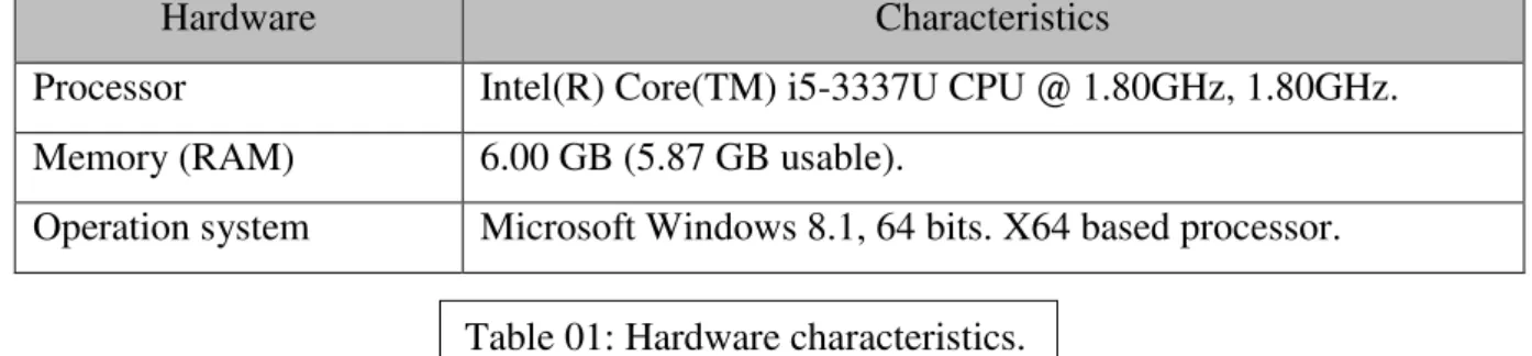
3.2.Hardware characteristics………...………..51
4. “WSN Simulation” interface……….………51
4.1.Simulation parameters………52
4.2.Simulation zone………..53
5. Simulation of the routing protocols………..55
5.1.First experimentation………..55 5.1.1. Number of rounds……….…..56 5.2.Second experimentation……….……….58 5.2.1. The 1st scenario………..58 5.2.1.1.Number of rounds……….58 5.2.1.2.Control packets……….59
5.2.1.3.First dead node……….60 5.2.1.4.Live Nodes………61 5.2.1.5.Data delivery to BS………...62 5.2.1.6.Residual energy……….62 5.2.2. The 2nd scenario……….63 5.2.2.1.Number of rounds……….………63 5.2.2.2.Control packets……….………64
5.2.2.3.First dead node……….65
5.2.2.4.Live Nodes………65
5.2.2.5.Data delivery to BS………..66
5.2.2.6.Residual energy………67
6. Conclusion………67
General conclusion………69
List of Figures
N° Title Page
Fig. 01 Wireless sensor network architecture 03
Fig. 02 Military applications of WSN 08
Fig. 03 Environment monitoring in WSN 08
Fig. 04 Precision agriculture in WSN 09
Fig. 05 Medical applications in WSN 09
Fig. 06 Habitat monitoring in WSN 10
Fig. 07 Home Automation in WSN 10
Fig. 08 Architecture of a sensor node 11
Fig. 09 Classification of data aggregation 13
Fig. 10 WSN Routing Protocols Classification 17
Fig. 11 Hierarchical routing architecture in WSNs 22
Fig. 12 Clustering-based topology 23
Fig. 13 Chain-based topology. 24
Fig. 14 Tree-based topology. 25
Fig. 15 Grid-based topology. 26
Fig. 16 Area-based topology. 27
Fig. 17 (a) Intra communication. (b) inter communication. 28
Fig. 18 Structure of PEGASIS protocol 29
Fig. 19 Diagram of PEGASIS protocol 30
Fig. 20 Diagram of EADAT protocol 32
Fig. 21 Structure of PANEL protocol 33
Fig. 22 Diagram of PANAL protocol 34
Fig. 23 Structure of Ring Routing protocol 35
Fig. 24 The first clustering round in LEACH-1R 38
Fig. 25 The other rounds in LEACH-1R. 39
Fig. 27 Flowchart of LEACH-1Rinter PEGASIS protocol 42
Fig. 28 LEACH-1R intra PEGASIS protocol 44
Fig. 29 LEACH-1R intra-inter PEGASIS protocol 45
Fig. 30 Radio energy dissipation model 50
Fig. 31 The interface of “WSNSimulation”. 51
Fig. 32 Simulation parameters. 52
Fig. 33 The simulation zone 53
Fig. 34 Simulation area 53
Fig. 35 The legend 54
Fig. 36 The results of simulation 54
Fig. 37 The checkboxes show 54
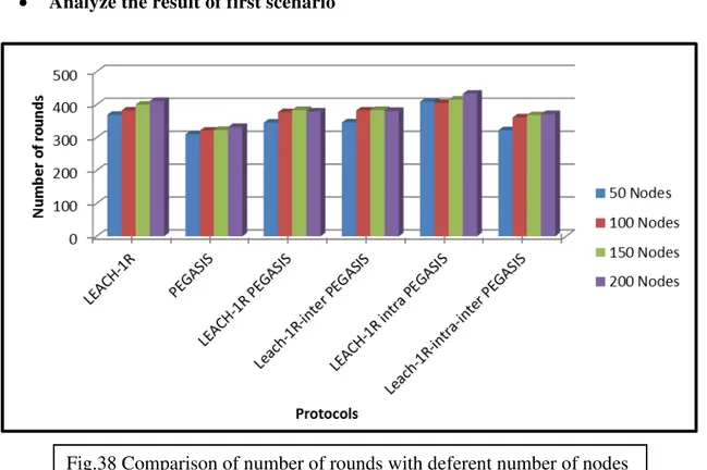
Fig. 38 Comparison of number of rounds with deferent number of nodes
56 Fig. 39 Comparison of number of rounds with deferent value of P 57 Fig. 40 Comparison of number of rounds for each protocol in 1st
scenario
58 Fig. 41 Comparison of # of control packet versus # of rounds in the 1st
scenario
59 Fig. 42 the first dead node (1st simulation scenario) 60 Fig. 43 Comparison of the live nodes versus # of rounds in 1st scenario. 61 Fig. 44 Comparison of the data received by BS versus # of rounds in 1st
scenario.
62 Fig. 45 Comparison of the residual energy versus # of rounds in 1st
scenario.
62 Fig. 48 Comparison of number of rounds for each protocol in 2nd
scenario
63 Fig. 49 Comparison of # of control packet versus # of rounds in the 2nd
scenario
64 Fig. 50 the first dead node (2nd simulation scenario) 65 Fig. 51 Comparison of the live nodes versus No. of rounds in 2nd
scenario.
65 Fig. 52 Comparison of the data received by BS versus # of rounds in
2nd scenario.
66 Fig. 53 Comparison of the residual energy versus # of rounds in 2nd
scenario.
List of Tables
N Title Page
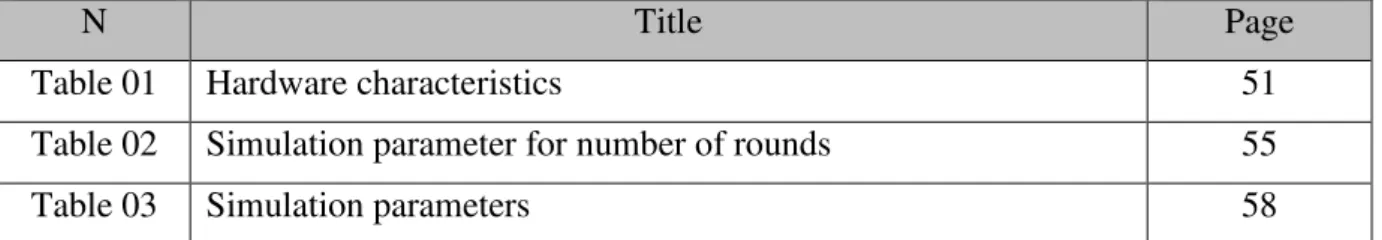
Table 01 Hardware characteristics 51
Table 02 Simulation parameter for number of rounds 55
List of Abbreviations
A ADC: analog to digital communication
AN : Anchor node B BS: base station C CH cluster head D DD Directed Diffusion E EADAT energy-aware data aggregation tree
G GUI graphical user interface
I ISM Industrial, Scientific and Medical
ITU-R International Telecommunication Union- Radio communications L
LEACH Low Energy Adaptive Clustering Hierarchy LEACH-1R
M MATLAB matrix laboratory
O
ON ordinary node
P
PANEL Position-based Aggregator Node Election protocol
PEGASIS Power Efficient Gathering in Sensor Information Systems R
RC ring change
S
SPIN Sensor Protocols for Information via Negotiation W
General
General introduction
Recent advances in micro-electro-mechanical systems (MEMS) technology, wireless communications, and digital electronics have enabled the development of cost, low-power, multifunctional sensor nodes that are small in size and communicate untethered in short distances. These tiny sensor nodes, which consist of sensing, data processing, and communicating components, leverage the idea of sensor networks based on collaborative effort of a large number of nodes. Sensor networks represent a significant improvement over traditional sensors.
A wireless sensor network is a collection of large number of sensor nodes and at least one base station. Sensor nodes are densely deployed either inside the phenomenon or very close to it. The position of sensor nodes need not be engineered or pre-determined. Nodes in sensor network have low communication and computation capabilities. The problem of energy resources is very difficult. Sensor nodes are constrained on energy supply and consumption, power consumption and bandwidth. When such constraints are combined with large number of nodes, it leads to many challenges to the design issues and management of sensor networks. These challenges are necessary for all the layers of networking protocol. At the network layer, the main objective is to find the energy-efficient and shortest routes and reliable forwarding of data from sensor nodes to the destination so that network lifetime is enhanced. Many researchers are currently working in developing various schemes that fulfill these conditions.
There are many protocols based on clustering hierarchy in WSNs. LEACH-1R (one round-LEACH) is one of the protocols that use clustering hierarchy in order to reduce energy consumption. Recently there arise some atypical hierarchical routings, which are variants of cluster-base routing and present special hierarchical architecture, including chain-based, tree-based, grid-tree-based, and area-based routing. PEGASIS is a pioneering chain-based hierarchical protocol. In PEGASIS, all nodes are organized into a linear chain for data transmission and data aggregation. This protocol has many deficiencies; long chain made long transmission delay and less scalability. The objective of our project is find new optimal technique based on cluster hierarchy and multi-chain communication for energy efficiency in WSNs.
This report is organized as follows:
The first chapter entitled “Overview of Wireless Sensor Networks” presents the general concepts related to the field of WSN.
The second chapter entitled “Hierarchical routing in wireless sensor networks” highlights the sections that cover classification of WSN routing protocols and gives the principle details of some protocols like PEGASIS, EADAT, PANEL and Ring Routing.
The third chapter entitled “Hierarchical Hybrid protocols LEACH-1R and PEGASIS” presents the main idea of our proposed protocols. Our proposed protocols are based on clustering in LEACH-1R and chain communication in PEGASIS. In the following order we present the description of LEACH-1R, LEACH-1R PEGASIS, LEACH-1R-inter PEGASIS, LEACH-1R-intra PEGASIS, LEACH-1R-intra-inter PEGASIS protocols.
The last chapter entitled “Simulation, Results, and Analysis” gives an overview of MATLAB environment, the evaluation of the existing protocols LEACH-1R and PEGASIS instead of our proposed protocols LEACH-1R PEGASIS, LEACH-1R-inter PEGASIS, LEACH-1R-intra PEGASIS, LEACH-1R-intra-inter PEGASIS in term of different metrics such as throughput to the base station, number of rounds, and residual energy. This section is concluded with results analyses.
Finally, a conclusion is given to summarize our main contributions in addition to a section that describes our ideas of the future work.
Chapter 01:
overview on wireless
sensor networks
1. Background:
Due to wireless sensor network, it is possible to perform various applications such as monitoring or tracking of deferent activities. Consequently, the field of WSNs has attracted the attention of scientific and industrial community.
In this chapter, we present an overview of WSNs. First, a definition of ad hoc and wireless sensor network, deferent type of WSNs and Factors influencing wireless sensor network design with application domains is provided. Secondly, Structure of wireless sensor networks and data aggregation in WSNs has been described.
2. Ad hoc network:
An ad-hoc network is a transitory or permanent association of nodes or mobile devices that do not depend on any fixed support infrastructure to establish intercommunication among them. Connection and disconnection is controlled by the distance among nodes and the face-to-face requirement of the implemented peer-2-peer (p2p) application, which may educational, commercial, or collaborative [1].
3. wireless sensor networks 3.1.Definition:
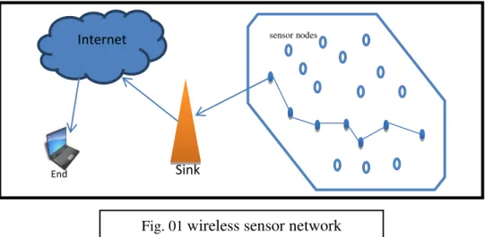
A wireless sensor network (WSN) defined as an ad hoc network especially consisting of a number of wireless sensors that are deployed on a given area, to ensure an accurate task, either for monitoring or for tracking or for both [2]. WSN is a collection of a large number of tiny low powers, low cost and multi-functional sensor nodes which are randomly and highly distributed either inside the system or very close to it [3, 4].
The sensor nodes have the capabilities to collect data and route data back to the sink and the end users. Data are routed back to the end user by multihop infrastructure architecture through the sink. The sink may communicate with the task manager node via Internet or Satellite. Internet Sink sensor nodes End user
Fig. 01 wireless sensor network architecture
3.2.Types of WSNs:
Depending on the deployment environment on earth, underground or underwater, there are several types of wireless sensor network.
3.2.1. Ground (Terrestrial) WSNs:
In this type of sensor networks, hundreds to thousands of sensors deployed randomly or pre-deployed on a given area. This type of WSNs is mainly used in the field of environmental monitoring and presents a challenge to the sustainability of the network in terms of management of energy [5].
3.2.2. Underground WSNs:
These very special sensor nodes are known for their high cost and the required logistics for maintenance and pre-planned deployment. Sensors are installed in the soil for agriculture or in the walls of a mine to monitor conditions in the soil. However, in this type of network, there is land node which has role of relaying sensed information by the underground nodes to the base station [6].
3.2.3. Aquatic (Underwater) WSNs:
This type of WSNs are still a great research challenge because of fact that environment in which the nodes are deployed is hostile and usually used for exploration. It's only possible to deploy a few nodes, these nodes are more expensive than terrestrial sensors, wireless communication is acoustic, the bandwidth is limited, the loss of signal is recurrent, propagation delays and synchronization problems are high [7].
3.2.4. Multi-media WSNs:
This type of WSNs allows monitoring of a tracker in real-time events such as images, videos and sound. These sensors are equipped with cameras and microphones. Importance is given for: good bandwidth which implies a high energy consumption; processing and data compression; good QoS. Advance planning is necessary for the deployment of these sensors [8].
3.2.5. Mobile WSNs:
In this most recent type of WSNs, nodes are capable of repositioning and autonomously reorganize the network. After initial deployment, nodes disperse to collect information. There's also a hybrid network that consists of the combination of mobile sensors and fixed sensors [9].
3.3.Factors influencing wireless sensor network design:
WSN design is affected by various factors like: production costs, operating environment, hardware constraints, network topology, transmission media, fault tolerance, scalability, and power consumption. These factors are of much importance due to their contribution in design and development of a protocol or algorithm for WSNs [10].
3.3.1 Production Cost:
The wireless sensor network comprised of huge number of sensor nodes, so the cost of a single node plays a crucial role in the justification of complete network cost [11]. The nodes production cost is a challenging issue and it should be kept as low as possible.
3.3.2 Operating Environment:
The nodes in sensor networks are densely deployed. So, they generally work unattended in inaccessible geographic locations. They might be working as follows: in busy intersections, on the surface or at the bottom of ocean, in the interior of machinery, in battlefield, attached to animals or fast moving vehicles etc. This list gives us an idea about under which conditions sensor nodes are expected to work [11, 12].
3.3.3 Hardware Constraints:
A sensor node is made up of four basic units: a sensing unit, a processing unit, a power unit, and a transceiver unit. There might be some application specific components attached with sensor node like: a power generator, a location finding system, and a mobilize [13]. The signals captured by sensing unit are sent to processing unit. The processing unit manages the process that creates the node collaborative to carry out the specified tasks. Transceivers unit connect node to network. Power unit must be backed by an energy scavenging unit like solar cell [11]. These nodes must [14]
consume extremely low power, operate in high volumetric densities,
have low production cost and be dispensable, be autonomous and operate unattended, be adaptive to the environment.
3.3.4 Network Topology:
The remote and unattended sensor nodes, which are more prone to failures, make topology management a challenging job. Node densities may be variable but at most 20 nodes per cubic meter [15]. The topology maintenance issues can be examined in following phases: Deployment phase, Post-deployment phase, Re-deployment of supplementary nodes [14].
3.3.5 Transmission Media:
In a multihop sensor network, communicating nodes are linked by a wireless medium. These links can be formed by radio, infrared or optical media. To enable global operation of these networks, the chosen transmission medium must be available worldwide. A low-cost and low-power transceiver is required by network. Due to some constrains and tradeoff between antenna efficiency and power consumption limits, the choice of carrier frequency in such cases to be of ultra-high range [14].
3.3.6 Fault Tolerance:
Some sensor nodes may fail or be blocked due to lack of power, have physical damage or environmental interference. The failure of sensor nodes should not affect the overall task of the sensor network. This is the reliability or fault tolerance issue. Fault tolerance is the ability to sustain sensor network functionalities without any interruption due to sensor node failures [14].
3.3.7 Scalability:
The number of sensor nodes deployed in studying a phenomenon may be in the order of hundreds or thousands. Depending on the application, the number may reach an extreme value of millions. The new schemes must be able to work with this number of nodes. They
must also utilize the high density nature of the sensor networks. The density can range from few sensor nodes to few hundred sensor nodes in a region, which can be less than 10 m in diameter [14]. The density can be calculated according to [16] as
µ(R) =(NπR2)/A
Where N is the number of scattered sensor nodes in region A; and R, the radio transmission range. Basically, µ(R) gives the number of nodes within the transmission radius of each node in region A.
3.3.8 Power Consumption:
The wireless node is able to equip with a limited power source. There are a few scenarios in which replacement of power resources not viable. So, the lifetime of nodes strongly depend on depletion time of battery [17]. In multihop network each node plays the dual role of data originator and data router. The failures of some affect significant changes in topology and may require the network re-organization [18]. Hence, the conservation and management of power take some additional significance.
3.4.Applications domains:
Sensor networks may consist of many different types of sensors such as seismic, low sampling rate magnetic, thermal, visual, infrared, and acoustic and radar, which are able to monitor a wide variety of ambient conditions that include the following:
temperature, humidity, pressure, noise levels,
vehicular movement, lightning condition, soil makeup, the presence or absence of certain kinds of objects, mechanical stress levels on attached objects, and
The current characteristics such as speed, direction, and size of an object. Wireless sensor networks enable a paradigm shift in the science of monitoring, and constitute the foundation of a broad range of applications related to security, surveillance, military, medical, and environmental monitoring. They can significantly improve the accuracy and density of scientific measurements of physical phenomena because large number of sensor can directly be deployed at places where experiments are failing. Some existing real life applications are given below.
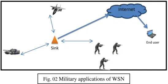
3.4.1 Military applications:
Sensor network research was initially driven by military applications such as surveillance and enemy tracking. Wireless sensor networks can be an integral part of military C4ISRT systems: command, control, communications, computing, intelligence, surveillance, reconnaissance and targeting. The rapid deployment, self-organization and fault tolerance characteristics of sensor networks make them a very promising sensing technique for military C4ISRT. Some of the military applications of sensor networks are monitoring friendly forces, equipment and ammunition; battlefield surveillance; reconnaissance of opposing forces and terrain; targeting; battle damage assessment; and nuclear, biological and chemical (NBC) attack detection and reconnaissance [14,19].
3.4.2 Environment Observation:
Environment monitoring networks span large geographic areas to monitor and forecast physical processes such as environment pollution, forest fire detection and flood detection etc. [19]
Internet
Sink
End user
Fig. 03 Environment monitoring in WSN Internet
Sink
End user
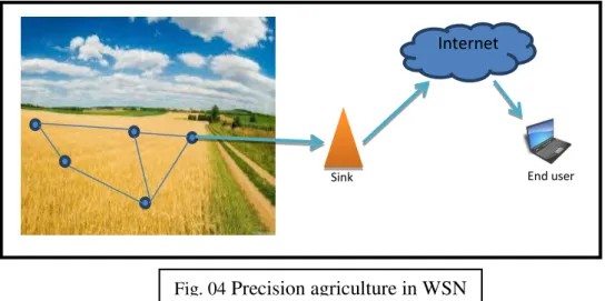
3.4.3 Precision Agriculture:
In agriculture sensor networks are used to monitor the pesticides level in the drinking water, the level of soil corrosion and the level of air pollution. They are also helping in strategic planning and counter measures to increase the yield of the crop [19].
3.4.4 Medical Applications:
In medical, sensor networks are used for tracking and monitoring doctors and patients inside a hospital. Each patient has small and light weight sensor nodes attached to them. Doctor may also carry a sensor node which allows other doctors to locate them within a hospital. Biosensors are implanted in the human body to monitor the patient’s physiological parameters such as heart beat or blood pressure. The data so collected is sent regularly to alert the concerned doctor on detection of an anomaly. Such an arrangement provides patients a greater freedom of movement instead of being constantly confined to the hospital bed [19].
Internet
End user Sink
Fig. 04 Precision agriculture in WSN
Internet
3.4.5 Habitat Monitoring:
Researchers in the life sciences are becoming increasingly concerned about activities of birds, small animals and insects. WSNs therefore can be used to gather information on the habitat of animals without disturbing them. [19]
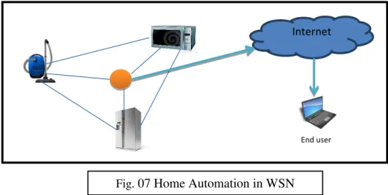
3.4.6 Home Automation:
As technology advances, smart sensor nodes and actuators can be buried in appliances, such as vacuum cleaners, micro-wave ovens, refrigerators. These sensor nodes inside the domestic devices can interact with each other and with the external network via the Internet or Satellite. They allow end users to manage home devices locally and remotely more easily [19].
Internet
End user
Fig. 07 Home Automation in WSN Internet
Sink
End user
3.4.7 Other Commercial Applications:
Sensors can be used in building for detecting and controlling of fire and smoke. In case of a fire in building, the deployed sensor network can track and scan the direction in which fire is expanding. Also sensors can be used to monitor the vibration in the building that can damage the structure [14].
4. Structure of wireless sensor networks 4.1. Sensor node structure:
A wireless sensor is a veritable embedded system with a wireless communication function, and that is capable to: [20]
Collect physical quantities such as heat, humidity, temperature, vibration, radiation, sound, light, movement, etc.
Convert them into digital values which are sent as sensed data to a remote processing station or base station.
In general, sensor has an operating system. TinyOS is the specifically operating system designed for sensors and is thereby the most used. And each sensor node includes four basic components. A sensing or actuating unit, a processing unit, transceiver unit and power supply unit [21, 22, 23]. Also, depending on the application, some modules are added: GPS, solar cell, a mobilizer etc. Fig.08 present general node architecture.
Power unit
mobilizer Position finding System
transceiver Power generator Processor Storage Sensor ADC
sensing unit Processing/ storage unit Communication unit
4.1.1. The sensing unit:
The sensing unit is responsible for gathering information from the environment as an input like temperature, pressure, light etc. and produces a related output in a form of electrical or optical signal. The analog signals produced by the sensor are converted to digital signals by the analog to digital communication (ADC) and fed into the processing unit [19].
4.1.2. The processing unit:
The processing unit is responsible for performing data operations such as data removal, data aggregation etc.
4.1.3. The communication unit ( Tranreceiver):
Communication unit is responsible to receive command or query from and transmit the data from processing unit to the base station. The transmitter and receiver are combined in to a single device called transreceiver. Sensor nodes often use ISM (Industrial, Scientific and Medical) band. The ISM bands are defined by ITU-R (International Telecommunication Union- Radio communications) [19, 24].
4.1.4. The power unit:
One of the most important components of a wireless sensor node is the power unit which supplies power to whole nodes system [24].
4.1.5. The Memory/storage unit:
Sensor nodes have very simple memory architecture. Sensor nodes use flash memories due to their cost and storage capacity [19].
4.2. Base station:
The base station controls the sensor nodes and acts as a gateway for data transmission to a remote server. The sensor nodes use short-range communication such as Wi-Fi or Bluetooth to transmit data to the base station. The base station uses long range communication such as GPRS or satellite to transmit collated data back to a server at a control center. It has a more powerful processor and more memory than the sensor nodes to
allow it to collate data from multiple sensors. Hence, the base station requires more power [25].
The Network may have one or more base station. A base-station may be a fixed node or a mobile node.
4.3. Data transmission:
The sensors coordinate among themselves to form a communication network such as a single multi-hop network or a hierarchical organization with several clusters and cluster heads to collect the data to sink node in the WSN. Since sensor nodes are energy constrained, it is inefficient for all the sensors to transmit the data directly to the base station.
Data Aggregation is the global process of gathering and routing information through a multi hop network with the objective of reducing resource consumption (in particular energy) and prolong the network lifetime in WSNs [26].
5. Data aggregation in WSNs:
Data aggregation is defined as the process of aggregating the data from multiple sensors to eliminate redundant transmission and provide fused information to the base station. All the aggregation nodes collect data from their children nodes and calculate the aggregation value. Then only the aggregated values are forwarded towards the sink. The aggregate value may be average, maximum (minimum), summation, etc. Which is calculated according to the application requirements.
The main purpose of the data aggregation is to reduce the power consumption by minimizing the number of data transmissions [27].
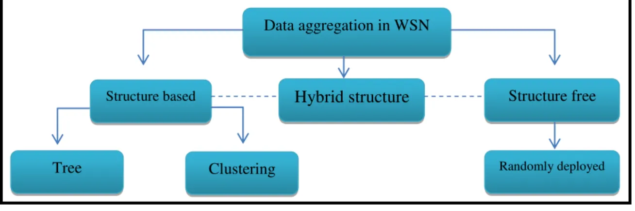
5.1.Classification of Data Aggregation Mechanisms:
According the WSN, Data aggregation mechanisms can be classified as structure-free, structure-based and hybrid structure [28].
Tree Clustering
Structure based Hybrid structure Structure free
Randomly deployed
Data aggregation in WSN
5.1.1. Structure-Free Data Aggregation:
When sensor nodes are randomly deployed in the environment, by nature, they require a free mechanism. The typical communication architecture for a structure-free data aggregation is the basic client/server architecture. To achieve the scalability, it is important to consider several key points such as the high amount of detected data and the communication sessions required to send them to the server. As the sensor nodes are energy constrained, it is inefficient for all the sensors to transmit the data directly to the base station. Because the communication is very expensive in terms of energy compared to the local processing.
5.1.2. Structure-Based Data Aggregation:
When sensor nodes are deployed at a large scale, it becomes difficult in terms of data aggregation and management the WSNs. whereas the structure-based data aggregations are defined with a set of algorithms, which divides the network into groups and/or levels. This group manages separately their data aggregation and reduced view of the entire network. However the structure-based mechanisms require an extra charge to organize the network and to maintain organization during the network lifetime.
5.1.3. Hybrid structure Data Aggregation:
Hybrid structure combines characteristics of both structure-free and structure-based is depending upon application.
6. Conclusion:
WSNs are a group of small sensor nodes which communicate through radio interface. The limited energy storage in the sensor node produces many challenges in the design of protocols for WSNs. One of the main challenges is energy efficiency and the ultimate objective behind the design is to keep the sensors life time as long as possible.
In the next chapter of our study we highlight the major routing protocols proposed in term of energy efficiency and network prolong life.
Chapter 02:
Hierarchical routing in
wireless sensor networks
1. Background:
Routing is one of the most important challenge issues that directly affected the performance of WSN. The main goal of the routing protocols in WSN is to develop efficient algorithms to reduce the power consumption and extend the life time of the network's nodes.
In this chapter, we present the routing issue in WSNs. Our aim is to provide better understanding of the research challenging in this field. The chapter is structured as follows: in section 2 we defined the routing in WSN. In Section 3 we classify the routing protocols in WSN under their appropriate category. In section 4 we expand in Hierarchical routing, its categories and communication types. In section 5 we highlight the clustering communication in WSN. Finally, in Section 6 we describe some Hierarchical protocols.
2. Routing in wireless sensor networks:
Routing is a process of finding a path between source and the destination [2, 9]. Routing in wireless sensor network is a challenging task due to characteristics that differentiate them from other communication and ad-hoc networks.
a) It is not possible to build global addressing scheme as there are relatively large number of sensor nodes which are densely deployed.
b) In comparison to typical communication networks, all applications of sensor networks require the flow of data which is collected (sensed) from multiple sources to a particular base station (BS).
c) Sensor nodes are tightly restricted to energy, processing and storage capacity, transmission power. Thus they require careful resource management.
d) Location information of sensors is crucial because data collection is based on the location.
e) Redundancy can occur in data traffic because multiple sensors may generate same data within the neighborhood. Such redundancy needs to be controlled by the routing protocols to improve energy and bandwidth utilization.
Due to such differences, many new protocols have been developed for routing the data in sensor networks.
3. Classification of routing protocols in WSNs:
WSN Routing Protocols can be classified into five ways [30], according to: The way of establishing the routing paths,
The network structure, The protocol operation,
The initiator of communications,
And how a protocol chooses a next-hop on the route of the forwarded message.
3.1.Initiator of Communication Based Routing Protocol
Communication Based Routing Protocol depends on the communication between network components, where they generally in sleep mode temporary [30, 31]. When any part of a network, the sink (destination, base station) node or the source node, needs service from
WSN Routing Protocols
initiator of
communications Path establishing
Network structure Protocol operation Next-hop selection Source Destination Hybrid Reactive Proactive Location-Based Hierarchical-Based Flat-Based Coherent and non-coherent QoS Based Negotiation Based Query Based Multipath Broadcast-based Hierarchical-based Location-Based Probabilistic Content-based
other part of network, it will initiate the routing with other part to send or receive the control or data packets.
Source Initiator Routing Protocol Destination Initiator Routing Protocol.
3.2. Path establishment Based Routing Protocols:
According to path establishment based routing protocols routing paths are established according to three types; proactive protocol, reactive and hybrid protocol [32].
3.2.1. Proactive Protocols:
Proactive routing protocols are those routing protocols those maintain consistent and correct routing tables of all network nodes by using periodic broadcasting of routing information throughout the network. Here in this category of routing protocols all routes are computed before their actual requirement. These routing protocols can be used both in flat and hierarchal structured networks.
3.2.2. Reactive Protocols:
A reactive routing protocol comes under on demand routing protocol category. So they do not maintain the global information of all the nodes in a network. Here the route establishment between source and destination is based on demand according to the requirement of the network.
3.2.3. Hybrid Protocols:
Hybrid Protocols are combination of both proactive and reactive routing protocols. This routing methodology is applied to large networks. These protocols use clustering approach which makes the network more stable and scalable.
3.3.Network Structure
3.3.1. Flat Routing:
In flat based network every node plays the same role and collaborates together to perform sensing task [33]. Due to the presence of large number of nodes, it is not feasible to assign global identifier for every node, data centric routing is used where the queries are
performed to the sender and data is transmitted to the receiver node. BS sends the queries to the selected regions and waits for the data response from the selected regions of sensor nodes.
Protocols come under flat based routing SPIN, directed diffusion, EAR, SAR, ACQUIRE, MCFA, CADR, RR, MCFA, GBR, IDSQ.
3.3.2. Hierarchical Routing:
Hierarchical routing is also called as cluster based routing [34, 35]. The main idea of developing the cluster based routing protocol is to reduce the network traffic towards the sink. The main objective of hierarchical routing is minimization of energy consumption of sensor nodes. In which higher energy nodes can be used to process and send the information while the low energy nodes can be used to perform sensing task. Only low energy nodes are participate for generating network path. Hierarchical routing is two layered routing mechanism where the one layer is used for selecting the cluster heads and other is used for routing.
Protocols comes under hierarchical based are: LEACH, PEGASIS, TEEN, APTEEN & HEED
3.3.3. Location-based:
Location based routing protocols are using location information to guide the route discovery [36]. In this the nodes are equipped with GPS and scattered in a particular network. The position of nodes can be determined with the help of GPS. On the basis of incoming signal strengths the distance between the neighboring nodes can be estimated. When the distance between any two nodes in the network is determined, we can know about the co-ordinates with the exchange of information or data with the neighboring nodes.
Protocols come under location based routing are GEAR, GAF, GOAFR, GDIR, MECN and SMECN.
3.4.Protocol Operation
3.4.1. Multipath-Based Routing:
Multipath routing protocols are those routing protocols those provide multiple path selection for a message to reach its destination thus increasing network performance and
decreasing delay in network [31, 37]. Due to increased overheads better network reliability is achieved through sending periodic messages network paths are kept alive and hence greater energy is consumed.
Protocols come under Multipath routing are: Multi path and Multi SPEED (MMSPEED), Sensor Protocols for Information via, Negotiation (SPIN).
3.4.2. Query-Based Routing:
Query based routing protocols works by sending and receiving queries for data [31,37]. In this category the destination node sends query of interest from a node through network and node with this interest matches the query and send back to the node which initiated the query. The query is normally written in high level languages.
Protocols come under Query based routing are: Sensor Protocols for Information via Negotiation (SPIN), Directed Diffusion (DD).
3.4.3. Negotiation-Based Routing Protocols:
Negotiation based routing protocols uses high level data descriptors for the removal of redundant data transmissions through negotiation process [31,37]. Generally these protocols make intelligent decisions either for communication or other actions based on facts such that how much resources are present.
Protocols come under Negotiation based routing protocols are : Sensor Protocols for Information via Negotiation (SPAN), Sequential assignment routing (SAR), Directed Diffusion (DD).
3.4.4. QoS-Based Routing:
QoS based routing protocols, network required to have a balance approach for the QoS of applications of system [31,37]. Here the application can be delay sensitive so to achieve this QoS metric. Here network have to look also for its energy consumption which is another metric when communicating to the sink. So in order to achieve QoS, the cost function for the desired QoS also needs to be mentioned.
Protocols come under QoS based routing are: Sequential assignment routing (SAR), SPEED, Multi path and Multi SPEED (MMSPEED).
3.4.5. Non-coherent and Coherent Data-Processing Based Routing:
In the operation of wireless sensor networks data processing is a major component. Hence, routing techniques follow different data processing techniques. There are two types of data processing based routing [24].
Non-coherent data processing: In this category of data processing, sensor nodes will locally process the raw data before being transmitted to other nodes for further processing of data. The sensor nodes that perform further processing of data are known as the aggregators.
Coherent data processing: In coherent data processing based routing, after minimum processing the data is forwarded to aggregators. The minimum processing basically includes tasks like duplicate suppression, time stamping etc. When all sensor nodes are sources and send their data to the central aggregator node, a huge amount of energy will be consumed and hence this process has a higher cost.
3.5.Next-Hop Selection Based Routing Protocols
3.5.1. Content-based routing protocols:
Content-based routing protocols determine the next-hop on the route purely based on the query content [37,32].
3.5.2. Probabilistic routing protocols:
These protocols based on assumption that all sensor nodes are randomly deployed and homogeneous [37, 32]. By using this routing protocol, next-hop neighbor for each message to be forwarded are randomly selected by nodes and probability of selecting a certain neighbor is inversely proportional to its cost.
3.5.3. Location-based routing protocols:
These protocols select the next-hop towards the destination based on the known position of the neighbors and the destination [37, 32]. The position of the destination may denote the centroid of a region or the exact position of a specific node.
3.5.4. Hierarchical-based routing protocols:
In case of hierarchical protocols, all nodes forward a message for a node (also called aggregator) that is in a higher hierarchy level than the sender [37, 32]. Each node aggregates the incoming data by which they reduce the communication overload and conserve more energy.
3.5.5. Broadcast-based routing protocols:
In broadcasting based routing protocols each sensor node in the network decides individually whether to forward a message or not [37, 32]. So the functioning of these protocols is very straightforward. So if a node decides to forward massage, it simply re-broadcasts the message and if it declines to forward message, the message will be dropped.
4. Hierarchical Routing protocols in WSNs:
Hierarchical architecture is proved to be an effective solution to the problem of scalability and energy efficiency. The typical hierarchical routing technique is clustering. Recently there arise some atypical hierarchical routings, which are variants of cluster-base routing and present special hierarchical architecture, including chain-based, tree-based, grid-based, and area-based routing. These types of atypical hierarchical routing are similar to the traditional clustering routing, but are more or less different in hierarchy division and communication scheme.
Hierarchical routing
Atypical hierarchical routing
Typical hierarchical routing clustering-based
area-based grid-based tree-based chain-based
4.1.Clustering based protocols:
In Clustering-based the network is partitioned into multiple clusters and nodes undertake two different tasks, cluster heads (CHs) and ordinary nodes (ONs) [38]. An ON only delivers its sensed data to its related CH, while a CH is responsible for collecting the data from its ONs and transferring data to the sink via hierarchical routing. The main Clustering-based protocols are: LEACH, TEEN, APTEEN and HEED…etc.
Advantages:
a) Energy Efficiency: With clustering in WSNs, energy consumption, lifetime of the network and scalability can be improved. Because only cluster head node per cluster is required to perform routing task and the other sensor nodes just forward their data to cluster head.
b) High-density: it is much easier to manage a set of cluster representatives (cluster head) from each cluster than to manage whole sensor nodes.
4.2.Chained based protocols:
In chain-based topology, one or more chains are constructed to connect the deployed sensor nodes for data transmission [39]. In a chain, a leader is selected to perform the task of data collecting, like a sink. Data is delivered along the chain, and ultimately to the leader
Sink
node. Data aggregation is performed during the process of transmission. The main chain -based protocols are: PGASIS, CCS, EBCRB, and CHIRON. …etc.
Advantages:a) Simple topology: chain-based routing needn’t CH competition and OH selection. b) Energy saving of local communication: node only sends data to its next node, which
is very close to it. Disadvantages:
a) Large delay: generally a chain is very long with large number of hops from one end to the other in the chain.
b) Imbalance of energy consumption: In such a topology, hop-by-hop data transmission is performed, so nodes far from the leader nodes have little data to deliver, while the nodes near the leader node suffer from too much data traffic.
c) Less robustness: If a sensor node fails, data transmission have to be terminated from the end of the chain to the failed node.
4.3.Tree based protocols:
In tree-based routing, a logical tree is constructed by all sensor nodes [39]. Data is delivered from leaf nodes to their parent ones severally. In turn, the parent nodes send the received data to their parent nodes towards to root nodes. Data aggregation is possibly performed in each node. The main Tree -based protocols are: EADAT, BATR, PEDAT, and ETR. …etc.
Sink
Advantages:
a) Simple topology structure: CH competition and OH selection don’t exist in such a topology.
b) Less energy consumption: Energy consumption is decreased compared with that in flat routing in WSNs, because flooding is not necessary for data transmission.
Disadvantages:
a) Less robustness: If a sensor node fails, the relative whole sub-tree is unable to work and new tree construction is needed.
b) Uneven energy consumption: the nodes closer to the BS perform more load in forwarding packets.
c) Less scalability: In large-scale tree-based networks, too many levels are constructed from one root to relative leaves.
4.4.Grid based protocols:
In a grid-based topology, the network is divided into various grids by geography approach [39]. Thus, grid-based routing generally belongs to location-aware routing. The distinct characteristic of the type of routing is that the routing operation is performed without any routing table. Once the position of the destination is achieved by the source, all routing operations are locally performed. The main Grid -based protocols are: PANAL, TTDD, HGMR and GMCAR …etc.
Sink
Advantages:
a) Simple structure: In grid-based networks, grids are regularly constructed by geographic locations and CH competition and ON selection can be left out.
b) Efficient data delivery: It can provide efficient data delivery in WSNs, in that each node only maintains a simple forwarder candidate set for it to transmit data.
Disadvantages:
a) Limited load balancing: data transmission is performed along the grids, and energy efficiency depends on balancing the geographic distribution versus occurrence of traffic.
b) Overload: Data communication is performed along the grids, and generally the transmission routing is fixed.
4.5.Area based protocols:
Area-based topology is an up-to-date structure, in which some sensor nodes are designated in a specific area and act as high-tier nodes [39]. Generally, such nodes perform the task of data collection from ONs and data transmission to the sink. The size of the area can be adjusted according to the load balancing requirements. Such topology is always used in mobile WSNs. The main Area -based protocols are: LBDD, Railroad, VLDD and Ring Routing …etc.
Sink
Advantages:
a) Simple topology structure: Only a specific area must be determined and it is easy to determine which nodes act as high-tier tasks.
b) Less energy consumption: data exchange is performed in local regions. This can avoid long-distance communication and decrease large energy dissipation.
c) Good load balancing: In such as topology, generally a mobile sink moves. This prevents traffic load from being distributed in a small space.
Disadvantages:
a) Less scalability: In a large-region network, a large area of specific region is needed. Data dissemination around the specific region results in large latency and energy consumption for data transmission.
b) High capital cost: Such a topology is generally used in mobile networks which contain high technology and difficult manufacturing.
5. Clustering communications in WSN:
From a routing perspective, clustering allows to split data transmission into intra-cluster (within a intra-cluster) and inter-intra-cluster (between intra-cluster heads and every intra-cluster head and the sink) communication [40].
Sink
5.1. Intra- communication:
Most of the earlier work on clustering assumes direct (one-hop) communication between member nodes and their respective cluster heads. All the member nodes are at most two hops away from each other. One-hop clusters makes selection and propagation of cluster heads easy, however, multi-hop intra-cluster connectivity is sometimes required, in particular for limited radio ranges and large networks with limited cluster head count. Multi-hop routing within a cluster has already been proposed in wireless ad-hoc networks. More recent WSN clustering algorithms allow multi-hop intra-cluster routing.
5.2. Inter- communication:
Earlier cluster-based routing protocols such as LEACH assume that the cluster heads have long communication ranges allowing direct connection between every cluster head and the sink. Although simple, this approach is not only inefficient in terms of energy consumption, it is based on unrealistic assumption. The sink is usually located far away from the sensing area and is often not directly reachable to all nodes due to signal propagation problems. A more realistic approach is multi hop inter-cluster routing that had shown to be more energy efficient. Sensed data are relayed from one cluster head to another until reaching the sink.
Fig.17 (a) Intra communication. (b) inter communication.
6. Description of protocols
6.1.Power Efficient Gathering in Sensor Information Systems (PEGASIS)
6.1.1. Definition:
PEGASIS (Power Efficient Gathering in Sensor Information Systems) a chain-based protocol proposed by Stephanie Lindesy et al [41]. The main idea in PEGASIS protocol is formed a chain of the sensor nodes using greedy algorithm, starting from the node farthest to the sink, or computes this chain by the BS and broadcasts it to all the nodes. So each node will receive from and transmit to closest neighbors and take turns for being the leader for transmit data to BS. This approach distributes the energy load evenly among the sensor nodes [42].
6.1.2. PEGASIS algorithm
a) Chain construction Phase
BS broadcasts the whole network a hello message to obtain basic network information such as ID of nodes alive and distance from each node to BS [43].
Set the node which is farthest from BS as the beginning node for the chain
The beginning node of the chain obtains the information of distance between itself and other nodes which have not joined the chain yet, finds the nearest node and sets it as the next node in the chain.
Start
End sink
Leader
b) Leader selection Phase A chain leader is selected randomly.
passes a token message to initiate a data gathering process c) In each round new leader should be chosen.
d) The chain should be reconstructed after one node is dying.
6.1.3. PEGASIS diagram
6.1.4. Advantages and disadvantages
a) Advantages:
Each node receives from and transmits to the close neighbors only. and take turns being the leader to transmit data to the BS.
Fig.19 Diagram of PEGASIS protocol
Wait for the token message Select a leader randomly
Send a token message
Node i leader?
Yes NO
Transmit data
Send a broadcast message
Defined the node farthest from BS and Constructed the Chain
Sink
Wait for the broadcast message
The leader in each round of communication will be at a random position on the chain, which is important for nodes to die at random locations.
nodes are dying at random places which make the sensor network robust to failures. The use of greedy chain protocol reduces the overhead of clustering process and
decreases the chance of data aggregation.
When a sensor node dies, chain is reconstructed to bypass the dead node. So the initial topology is not affected.
The leader node receives all the aggregated data and transmits further to the base station.
b) Disadvantages:
It is very difficult to assume that all nodes have global knowledge of the network. All nodes must be able to communicate directly to the sink, as a leader.
PEGASIS is not suitable for networks with time varying topology. The large transmission delay because of the long chain structure.
PEGASIS suffers from the problem of scalability (scalability vary low).
6.2.Energy-Aware Data Aggregation Tree (EADAT)
6.2.1. Definition:
EADAT (energy-aware data aggregation tree) tree-based protocol is an energy-aware distributed heuristic to generate an aggregation tree [39]. the main goal of this algorithm is to tackle the problem of energy shortage by considering energy-aware data-centric routing. The algorithm is initiated by the sink which broadcasts a control message. The sink assumes the role of the root node in the aggregation tree.
6.2.2. EADAT algorithm [44]
a) The tree construction
Broadcasts a control message by the sink (The control message has five fields: ID, parent, power, status and hop count).
Assumed the sink as the root node in the aggregation tree.
Each node chooses the node with the higher residual power and shorter path to the sink as its parent.
When the timer times out, the node v increases its hop count by one and broadcasts the control message.
b) The tree re-construction
When the residual power of a sensor falls below a threshold The node broadcasts help messages and shuts down its radio.
A child node upon receiving a help message, switches to a new parent in the tree if it exists.
Or it enters into a danger state.
6.2.3. EADAT diagram
The node i increases its hop count by one Broadcasts
The control message
marks node j as a leaf node
marks node j as a non leaf node If node j receive a
message indicate that its parent is
node i
Yes NO
Node Sink
chooses the node with the higher residual power and shorter path to
the sink as its parent sets up its timer to Ti assumes The sink as a root
Broadcasts The control message Wait for The control
message
If the timer
times out Yes
NO
6.2.4. Advantages and disadvantages
a) Advantages:
More load burden is performed due to the high chance to become a non-leaf node if it has a higher residual power.
The algorithm is not very complex. b) Disadvantages:
Large transmission delay.
6.3.Position-based Aggregator Node Election protocol (PANEL)
6.3.1. Definition:
Position-based Aggregator Node Election protocol (PANEL) [40] is a position-based clustering routing protocol for WSNs. PANEL supports asynchronous sensor network applications where the sensor node readings are fetched by the BSs. The main goal of PANEL is to elect aggregators, i.e., CHs, for reliable and persistent data storage applications. PANEL assumes that the nodes are deployed in a bounded area, which is partitioned into geographical clusters. The clustering is determined before the deployment of the network, and each node is pre-loaded with the geographical information of the cluster to which it belongs [45].
sink
Fig.21 Structure of PANEL protocol
Reference point. Cluster head
Reference point:
PANEL introduces a notion of reference point. At the beginning of each epoch, a reference point Rj is computed in each cluster j by the nodes in a distributed manner in terms of the epoch number [46], as follows:
Where Qj is the position of the lower-left corner of cluster j. Furthermore, the current epoch number e is known by every node and the computation consists in calling a pseudo-random function H(e) that maps e to a relative position Q inside the cluster, i.e.,:
Where Q ∈ (−δd, d + δd) × (−δd, d + δd), d is the size of the cluster, and δ < 1 is a parameter which expresses the magnitude of this re-sizing operation in percent of the original cluster size d.
6.3.2. PANAL algorithm [39]
a) Determined the cluster of each node (pre-loaded the nodes with the geographical information of the cluster to which it belongs).
b) The deployment of nodes in a bounded area. c) Compute the reference point of each point.
d) Elect the CH (the node that is the closest to the reference point).
6.3.3. PANAL diagram
Rj = Qj +Q
H(e)=Q
deployed the nodes in a bounded area
Compute the reference point of each cluster
Elect the CH
the node that is the closest to the reference point
6.3.4. Advantages and disadvantages
a) Advantages:
energy-efficient protocol that ensures load balancing because each node is elected aggregator
The clusters are mainly created.
Besides synchronous scenes, PANAL is also supports asynchronous applications.
b) Disadvantages:
The assumption that the clusters are determined before deployment and thus cannot be applied to WSN dynamics;
Geographical position information of the nodes is used to determine which node should be the aggregators.
6.4.Ring Routing Protocols
6.4.1. Definition:
The ring routing protocol proposed a ring topology in which the ring consist of a one-node-width, closed strip of nodes that are called the ring nodes [39]. After the formation of the ring, neighbor discovery is performed to determine the neighboring rig nodes. The ring acts as a rendezvous for the events and queries. The sink communicates with the ring by forwarding packets of its location information towards the network center by a follow-up manner, and the ring nodes conserve the current information of the sink at all times. The source nodes query the ring by a similar communication way. Moreover, he ring structure can be changed to prevent the ring nodes from dying quickly. So, the ring nodes must switch roles with regular nodes from time to time.
Sink Network center Ring radius Anchor node ANPI packet Ring node
6.4.2. Ring routing algorithm [47]
a) Ring Construction
Determined the ring radius, the network center, and certain threshold to select node candidates.
Select the nodes candidates depending on previous parameters. Choose the starting node.
Selected the ring nodes in a greedy manner.
If the starting node cannot be reached, Repeat the previous procedure is repeated with selection of different neighbors at each hop.
If after a certain number of trials the ring cannot be formed, the radius is set to a different value and the procedure above is repeated.
b) Advertisement of Sink Position
The sink selects the closest node as its new anchor node (AN). Broadcasts an AN Selection (ANS) packet.
Informed the old AN about the position and the MAC address of the new AN by another ANS packet.
Sends an AN Position Information (ANPI) packet towards the ring. Receive an ANPI packet by a ring node.
The ring node shared this information by sending an AN Position Information Share (ANPIS) packet to its clockwise and counter-clockwise ring neighbors.
c) Obtaining Sink Position From the Ring
If a source node, need to transmit data to the sink, it has to obtain the position of the AN first. The fresh position of the AN is stored in the ring. For that:
The source node sends an AN Position Information REQuest (ANPIREQ) packet towards the ring.
The ring node which receive the ANPIREQ packet generates an AN Position Information RESPonse (ANPIRESP) packet which contains the current AN’s position and send it to The source node.