Research Programme of the Research Fund for Coal and Steel Steel RTD
Project carried out with a financial grant of the
Research Programme of the Research Fund for Coal and Steel
Final Report
Technical Report No: 6
Period of Reference: 01/07/04 – 30/06/07
Technical Group: TGS8 “Steel products and applications for buildings, construction and industry”
ROBUSTNESS - Robust structures by joint ductility Contract Number: RFS-CR-04046
Contractors: Institute of Structural Design, University of Stuttgart, Germany Institute of Mechanics and Civil Engineering, M & S Department, University of Liège, Belgium
Arcelor Profil Luxembourg S.A.-Research, Product Department Structural, Luxembourg
PSP Technologies GmbH, Engineering Service Company, Germany
Department of Mechanical and Structural Engineering, University of Trento, Italy
Location: see separate list
Co-ordinator: Institute of Structural Design, University of Stuttgart, Germany Authors: as given in the introductions
Commencement Date: 01/07/04 Completion Date: 30/06/07
Locations of the project partners: Institute of Structural Design Universität Stuttgart (USTUTT) Pfaffenwaldring 7
70569 Stuttgart Germany
Institute of Mechanics and Civil Engineering, M & S Department University of Liège (ULg)
1 Chemin des Chevreuils 4000 Liège 1
Belgium
Arcelor Profil Luxembourg S.A.-Research Product Department Structural
Rue de Luxembourg 66 4009 Esch-sur-Alzette Luxembourg
PSP – Prof. Sedlacek & Partner (PSP) Technologien im Bauwesen GmbH Pauwelsstraße 19
52074 Aachen Germany
Department of Mechanical and Structural Engineering Università degli Studi di Trento (UNITRENTO) Via Mesiano 77
38050 Trento Italy
D
ISTRIBUTION
L
IST
Members of the technical group TGS8:
CM LG. CAJOT Arcelor Profil Luxembourg S.A. Reimbursed:
A. KÄHÖNEN OUTOKUMPU, Sverige
A. KARAMANOS MSRS, Greece
A. KLIMPEL SUT, Poland
J. KOUHI FCSA, Finland
J.K. KRISTENSEN FORCE, Denmark
H. LENGER BOEHLER, Austria
J. ORDIERES MERE UNIV RIOJA, Spain W. SALVATORE UNIV PISA, Italia
G. SEDLACEK RWTH, Germany
Not reimbursed:
A. BANNISTER CORUS UK, United Kingdom T. BRAINE-BONNAIRE ARCELOR, France
G. DEMOFONTI CSM, Italia
T
ABLE OF
C
ONTENTS
1
Introduction ___________________________________________________________ 21
2
Systematic analysis of existing data ________________________________________ 23
2.1 General _________________________________________________________________ 23 2.2 Basic guiding principles to robustness and common work________________________ 242.2.1 Preventing the progressive collapse: the strategies _____________________________________ 24 2.2.2 Structural robustness and codes ____________________________________________________ 25 2.2.3 The European approach to robustness _______________________________________________ 25 2.2.4 Ductility: a strategy to achieve robustness ____________________________________________ 28 2.2.5 Beam-to-column joint modelling: the component method ________________________________ 29
2.3 Database overview ________________________________________________________ 30 2.4 Conclusions ______________________________________________________________ 32
3
Concepts and strategies __________________________________________________ 33
3.1 General _________________________________________________________________ 33 3.2 Different strategies to achieve robustness _____________________________________ 34 3.3 Investigations on the event “Loss of a column” _________________________________ 36 3.4 Investigations on the event “Loss of a bracing”_________________________________ 38 3.5 Investigation on the event “Fire” ____________________________________________ 39 3.6 Investigation on the event “Earthquake”______________________________________ 40 3.7 Conclusions ______________________________________________________________ 414
Experiments and evaluation ______________________________________________ 42
4.1 General _________________________________________________________________ 42 4.2 Concept in view of the event “Loss of a column” _______________________________ 43 4.3 Substructure test__________________________________________________________ 434.3.1 General _______________________________________________________________________ 43
4.3.2 Design of an “actual” composite building according to Eurocode 4 recommendations__________ 44
4.3.2.1 Introduction _______________________________________________________________ 44
4.3.2.2 Design of the structural members ______________________________________________ 44 4.3.2.3 Design of the structural joints subjected to hogging bending moments _________________ 45 4.3.2.4 Verification of the internal main frame modelled with the predicted joint properties_______ 47
4.3.2.5 Conclusions _______________________________________________________________ 48
4.3.3 Extracted substructure tested at Liège University ______________________________________ 48
4.3.3.1 Introduction _______________________________________________________________ 48
4.3.3.2 Substructure geometric layout _________________________________________________ 49 4.3.3.3 Reinforcement and stud layouts of the substructure ________________________________ 49 4.3.3.4 Joint and column base configurations within the substructure ________________________ 50 4.3.3.5 Simulation of the lateral restraint during the test___________________________________ 50
4.3.3.6 Conclusions _______________________________________________________________ 51
4.3.4 Substructure test results __________________________________________________________ 52
4.3.4.1 Introduction _______________________________________________________________ 52
4.3.4.2 Characterisation of the constitutive materials _____________________________________ 52
4.3.4.3 Geometrical measurements ___________________________________________________ 53
4.3.4.4 Description of the load path during the test_______________________________________ 53
4.3.4.5 Test equipments____________________________________________________________ 54
4.3.4.6 Substructure test results ______________________________________________________ 56
4.3.5 Conclusions ___________________________________________________________________ 62
4.4 Joint tests________________________________________________________________ 62
4.4.1 General _______________________________________________________________________ 62
4.4.2 Composite joint tests ____________________________________________________________ 63
4.4.2.1 General __________________________________________________________________ 63
4.4.2.2 Design and dimensions of the joint test specimens _________________________________ 64
4.4.2.3 Test setup_________________________________________________________________ 65
4.4.2.4 Material characteristics ______________________________________________________ 65 4.4.2.5 Properties of the joints_______________________________________________________ 66 4.4.2.6 Results of the joints under pure bending exposure _________________________________ 67 4.4.2.7 Results of the M-N-interaction ________________________________________________ 69
4.4.2.8 Conclusions _______________________________________________________________ 73
4.4.3 Steel joint tests _________________________________________________________________ 73
4.4.3.1 General __________________________________________________________________ 73
4.4.3.2 Design and dimensions of the steel joint test specimens _____________________________ 74
4.4.3.3 Test setup_________________________________________________________________ 74
4.4.3.4 Material characteristics ______________________________________________________ 75
4.4.3.5 Test results________________________________________________________________ 75
4.4.3.6 Evaluation of the test results __________________________________________________ 79
4.4.3.7 Conclusions _______________________________________________________________ 81
4.5 Component tests __________________________________________________________ 82
4.5.1 General _______________________________________________________________________ 82
4.5.2 Experimental study on concrete specimens ___________________________________________ 82
4.5.2.1 General __________________________________________________________________ 82
4.5.2.2 Layout of the specimens _____________________________________________________ 83
4.5.2.3 The tests__________________________________________________________________ 84
4.5.2.4 Material properties__________________________________________________________ 85
4.5.2.5 Test results________________________________________________________________ 85
4.5.2.6 Tension stiffening effect _____________________________________________________ 88
4.5.2.7 Conclusions _______________________________________________________________ 89
4.5.3 Experimental tests on T-stubs _____________________________________________________ 90
4.5.3.1 General __________________________________________________________________ 90
4.5.3.2 Layout of the specimen ______________________________________________________ 90
4.5.3.3 T-stub tests under tension ____________________________________________________ 91 4.5.3.4 T-stub tests under axial and shear force__________________________________________ 92
4.5.3.5 Material properties__________________________________________________________ 92
4.5.3.6 Test results of the tension tests ________________________________________________ 93 4.5.3.7 Test results of the tests under tension and shear force_______________________________ 94
4.5.3.8 Conclusions _______________________________________________________________ 95
4.5.4 Test on the connection ___________________________________________________________ 96
4.5.4.1 General __________________________________________________________________ 96
4.5.4.2 Layout of the specimens _____________________________________________________ 97
4.5.4.3 The tests__________________________________________________________________ 97
4.5.4.4 Test results________________________________________________________________ 98
4.5.4.5 Conclusions ______________________________________________________________ 100
4.6 Summary and conclusions of the experimental results __________________________ 101
5
Numerical and analytical studies _________________________________________ 103
5.1 General ________________________________________________________________ 103 5.2 Validation of the numerical tools ___________________________________________ 1035.2.1 Introduction __________________________________________________________________ 103
5.2.2 Validation of FINELG with the experimental tests ____________________________________ 103 5.2.3 Benchmarking of other software - loss of a column____________________________________ 105
5.2.3.1 General _________________________________________________________________ 105
5.2.3.2 Description of the structure benchmark model 3__________________________________ 105
5.2.3.3 Results __________________________________________________________________ 105
5.2.4 Benchmarking of other software - loss of a bracing____________________________________ 106
5.2.4.1 General _________________________________________________________________ 106
5.2.4.2 Description of the structure benchmark model 2__________________________________ 106
5.2.4.3 Results __________________________________________________________________ 106
5.3 Investigations on the event “Loss of a column” ________________________________ 107
5.3.1 Introduction __________________________________________________________________ 107
5.3.2 Numerical studies of 2D and 3D structures __________________________________________ 108
5.3.2.1 Introduction ______________________________________________________________ 108
5.3.2.2 Investigations on a 2D-system________________________________________________ 108
5.3.2.3 Investigation on a 3D-system ________________________________________________ 114
5.3.3 Numerical studies of the simplified substructure ______________________________________ 117
5.3.3.1 General _________________________________________________________________ 117
5.3.3.2 Validation of the simplified substructure modelling _______________________________ 119 5.3.3.3 Parametrical studies on the simplified substructure________________________________ 122 5.3.4 Development of analytical methods to predict the development of the membrane forces _______ 127
5.3.4.1 Introduction ______________________________________________________________ 127
5.3.4.2 Analytical prediction of the M-N interaction resistance curve of composite joints________ 127 5.3.4.3 Analytical procedure to predict the development of the membrane forces in a structure ___ 133
5.3.4.4 Conclusions ______________________________________________________________ 134
5.4 Investigations on the event “Loss of a bracing”________________________________ 134
5.4.1 General ______________________________________________________________________ 134
5.4.2 Dimensions and properties of the car park frame______________________________________ 135 5.4.3 Applied loads at the car park _____________________________________________________ 136 5.4.4 Procedure of the numerical simulation______________________________________________ 137 5.4.5 Numerical simulations for “Loss of a bracing” _______________________________________ 138 5.4.5.1 Calculation of the undamaged frame structure ___________________________________ 138 5.4.5.2 Calculation for “Loss of a bracing” ____________________________________________ 138 5.4.6 Further parametrical studies for the car park frame ____________________________________ 140
5.4.6.1 Introduction ______________________________________________________________ 140
5.4.6.2 Examination of the car park as pure sway-frame__________________________________ 140 5.4.6.3 Examination of different joint characteristics for the car park frame __________________ 142 5.4.6.4 Examination of the size of the column profile____________________________________ 143
5.4.7 Conclusions __________________________________________________________________ 143
5.5 Investigation on the event “Fire” ___________________________________________ 143 5.6 Investigation on the event “Earthquake”_____________________________________ 145
6
Design requirements and design criteria ___________________________________ 147
6.1 General ________________________________________________________________ 147 6.2 Conclusions for the event “Loss of a column” _________________________________ 148 6.3 Conclusions for the event “Loss of a bracing”_________________________________ 149 6.4 Conclusions for the event “Fire”____________________________________________ 150 6.5 Conclusions for the event “Earthquake” _____________________________________ 1517
Summary ____________________________________________________________ 154
8
Outlook ______________________________________________________________ 158
A
BSTRACT
In view of recent disasters and their immense economical and human consequences more and more focus is given not only on the safety of structures - to reduce the risk for the life of people by collapse even under exceptional loading – but on minimizing the disastrous results and to enable a quick rebuilding and reuse. One crucial mean to achieve this aim is the design of redundant robust structures. Robustness prevents the collapse of the total structure when only parts of the structure are damaged or destroyed. To avoid progressive failure, redundant structures with inherent sufficient ductile behaviour allowing deformations when a local failure occurs, have to be built. Redundancy can be achieved by allowing force redistribution within a structural system. Therefore the single sections and joints have to be especially designed and optimized, not necessarily requiring additional fabrication costs. But until now no specific rules for robustness by ductile joints exist. The aim of the present project is to define general requirements for ductile joints as part of a structural system subjected to exceptional unforeseen loading.
F
INAL
S
UMMARY
Objectives of the project
The objective of this project is to encourage and to promote the wider use of composite and steel frames by increasing the robustness of structures. This will be achieved by using the inherent advantage of steel, designing especially highly ductile structures. The four main objectives of robust design may be summarized:
• Prevent progressive failure caused by local damage • Reduce risk of life by collapse under exceptional loads • Minimise disastrous results
• Enable quick rebuilding and reuse
A progressive failure of the whole structure can be prevented by robust design. Robustness ensures structural safety by preventing the collapse of the total structure when only one part of the structure is damaged or destroyed. This can be achieved by enabling the joints to provide large rotations, so that membrane forces can be activated allowing a redistribution of internal forces. Thus an adaptive structure is created which keeps sufficient strength even under exceptional loading and large deformations. By increasing deformations joints are subjected to increased tensile forces, while bending moment exposure of the joints decreases or is even inversed. Within the research project various experimental investigations are made on the behaviour of the joints under large deformations and combined loading of bending and tension, including a full scale test of a substructure, a number of joint tests and numerous component tests. To derive robustness requirements, different structural systems subjected to exceptional events are numerically investigated in order to see how the structures work when part of the structure is destroyed as well as how and how far redistribution takes place. So the project aim has been creating redundant structures allowing for moment and force redistribution
• by defining requirements for ductile joints and sections • by developing new ductile joint solutions
Comparison of initially planned activities and work accomplished
The work of this project closely followed the original work plan and the distribution of work according to the different work packages was kept. The partners made only minor adjustments in order to better achieve the objectives of the project with regard to the numerical investigations. The following adjustments were thoroughly discussed and agreed on during the coordination meetings:
The Work Package 2 “Requirements“ has been recognized as key for directing the project. So all the other activities refer to the aims defined by Work Package 2 and have oriented their investigations in order to derive the necessary requirements at least for a certain choice of structural systems. Thus the decision was to prolong that WP for the whole project runtime.
As it was recognized that there were not just two types of calculations “simplified and sophisticated” system calculations, but a cascade of different levels of sophistication already at an early stage the decision was taken to merge Work Package 3 and Work Package 6 due to the close interrelation. So also in this report the work packages are presented as one unit leading to conclusions which at the end allowed us to develop more detailed design criteria.
Description of activities and discussion
During the project runtime extensive investigations were carried out and presented to the partners at the six coordination meetings for discussion. The intermediate results were reported regularly in the
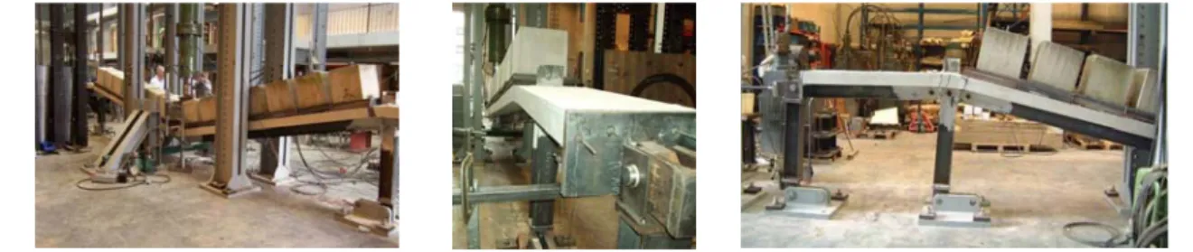
technical reports. It should be mentioned that nearly all partners had the opportunity to attend the experimental substructure test which was carried out at University of Liège in September 2006.
An Access database has been created which collects and analysis literature regarding the questions of accidents, exceptional loading, progressive collapse, requirements. This will serve also for future research and discussion.
Extensive experimental investigations on the behaviour of joint ductility and resistance as well as on the behaviour of numerous components (steel, concrete and composite) were carried out to be able to define requirements for robust design. Thereby a data bank is created the relevance of which goes far beyond the single aims of this project but may form the preformed basis of future efficient and robust joint design.
Further on an additional highlight should be mentioned: The experiments on components, joints and the substructure have been organised in a very consequent way to allow already experimentally building a full chain of recognitions: The same material, the same components, the same loadings were applied, so that the results of all single tests strongly support each other.
The aim of investigations presented here is not so much that it allows already to list design criteria in general for all events and cases which may be thought of but that for a choice of events and especially for the event “Loss of a column” as a prototype an in-depth strategy has been developed and realized up to practical design requirements that now may be followed by similar investigations on further events that are characteristic for exceptional scenarios. The concept or strategy developed with this project may thus serve as model guide.
Conclusions
This section summarises in short the conclusions which have been drawn at the end of each main chapter.
Firstly the investigations for the exceptional event “Loss of a column” are addressed. An extensive experimental test program including a substructure test, a number of joint tests and numerous component tests which have been based on each other were performed by different partners. All tests were successfully finalized. In the substructure test it was possible to observe the development of the catenary action within the frame and its effects on the joints. In particular, a very good ductility of the joints was achieved with a maximum observed rotation of 190 mrad. The composite joint tests aimed on the characterization of the behaviour of these joints under sagging and hogging bending moment with and without tension force and to obtain the M-N-interaction resistance curve. The steel joint tests aimed at the investigation of the membrane effect in the endplate depending on the endplate thickness and the bolt arrangement. The joint tests confirmed the findings of the substructure test, e.g. the very good ductility of the joints. In particular it was demonstrated that only ductile components were activated to pass from the behaviour under pure bending to the behaviour under pure tensile load. The component tests analyzed each component which was part of the substructure and the joint configuration. These tests gave information about the influence of each component on the global behaviour of the joint and, in particular, the component tests highlighted the effects of the development of the membrane forces within the components in bending or the highly ductile tension bar in the concrete slab. General criteria, derived from the experimental tests, to improv the deformation capacity of single components are given in § 4.6.
The experimental tests had an additional task by validating the numerical tools. Numerical investigations were performed on the tested substructure in order to compare the numerical prediction to the experimental results. From this comparison, the difficulty to model the actual behaviour of joints subjected to combined bending moments and axial loads was illustrated. However, it was shown that it is possible to model the behaviour of the joints with equivalent double-T beams if the developed membrane forces within the structure are not too important.
Furthermore the numerical simulations for the event “Loss of a column” included a benchmark study at a steel frame building to validate the different softwares used by different partners involved in the numerical calculations. The results of the different softwares were in good agreement and in the following numerical analyses for 2D and 3D structure have been performed including extensive parametrical studies which subsequently permitted to observe the redistribution of the loads within the
structure and to have an idea on the requested ductility as a consequence of the event “Loss of a column” at the structural element level. Besides the numerical simulations have contributed to develop, simplified analytical methods to predict the response of a framed structure caused by the “Loss of a column”. Through 2D numerical analyses, it was shown that it is possible to simulate very accurately the response of a structure through the proposed substructure. In addition, parametrical studies on the substructure were conducted so as to identify the parameters to be included in the developed analytical procedures. The developed analytical procedure is able to estimate the M-N interaction resistance curve of composite joints. Through comparisons to the results of the experimental test performed on the substructure composite joint in isolation, it was shown that the developed method permits to obtain a very accurate prediction of the composite joint behaviour when subjected to combined bending moments and tensile loads. With the so-obtained substructure response, it is then possible, knowing the maximum concentrated load Q to be supported by the system (what is possible with the analytical procedures presented in the PhD thesis of Luu Nguyen Nam Hai [88]), to predict the maximum vertical displacement associated to the considered column loss (as illustrated in Figure 6-2) and, as a result, the requested rotation capacity at the joint level. This analytical procedure is also included in more details in the design handbook [34].
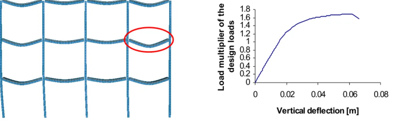
Secondly investigations for the event “Loss of a bracing in a car park” have been carried out. These investigations were limited to numerical simulations only. At first a benchmark study was performed to validate the different softwares of the different partners and the results of the various softwares corresponded very well. Next the “Loss of a diagonal bracing” in the bottom storey was simulated at a 2D composite framed structure with partial-strength joints. Afterwards parametrical studies were executed to investigate the influence of joint characteristics and properties of the structural members to the collapse resistance and to the redistribution behaviour within the structure. An important finding of these numerical calculations was that the collapse resistance of the car park frame was decisively depending on the bearing capacity of the chosen column profile. The remaining stiff panel effect of the undamaged bracings in the upper storeys still provides a frame effect and in addition the moment resistance of the semi-rigid joints also creates a moment resisting frame where the resulting rotation requirements for the joints are not extremely high. A crucial aim of the numerical simulations was in addition to determine requirements for the joints which allow for redistributions of loads within the structure when “Loss of a bracing” occurs and avoid premature joint failure. First minimum requirements for the joints concerning the ductility have been determined by the numerical studies and are presented in the corresponding chapter.
For the event “Fire” two states have to be differentiated. On one hand localised fire influences only cal structural members leading to local failure of members like loss of a column or a bracing. So the lo-cal fire may be translated e.g. to the event “Loss of a column” or “Loss of a bracing”. This has been shown for a given example. At the other hand a fully engulfed fire is no more a problem of robustness of structure but a problem of global fire resistance of the building which has to be designed in an inde-pendent “hot” design.
For the exceptional event “Earthquake” investigations were concentrated to collect and to check the most important codes and standards worldwide concerning provisions ensuring a structural ductile behaviour. Thereby main focus was given to connection requirements of steel as well as of concrete structures. But it have to kept in mind that the different nature of the actions associated with seismic events or an accidental actions and the consequent different structural behaviour doesn’t allow the extension of the available seismic detailing rules also to robustness without further studies. Certainly, the rules provided by seismic codes may be an interesting reference because the knowledge in seismic design is built up of decades of research in basic principals.
Exploitation and impact of the research results
As a result of the research work first basics in the field of robustness have been developed. By summarizing the state-of-the-art concerning robustness strategies implemented in standards all over the world a large data base has been installed. The numerical and experimental work results in first design requirements which have to be provided by the structural members and joints. So possible improvements could be pointed out. Meanwhile within Europe and other parts of the world an intensive discussion on “ROBUSTNESS” has started. Two COST initiatives COST C26 “Urban Habitat Constructions under catastrophic Events” which deals with exceptional loading and COST TU06001
“Robustness” which deals with robustness including the aspects of safety and reliability have recently started. The members of this research group have brought the results of this project into these COST actions. The action underline the current need of investigations in this field. The advantage of the research done in this project is that it is application oriented and thus may direct the general discussion in a more practical direction aiming at the rules and recommendations which can be realized. As also codified rules are started to be developed in Europe (…,Draft Model Code) as well as in USA and Canada it is of high importance to bring in the experience of this research work. As in this project the different national background of each partner how to apply and interprete Eurocode rules was brought together and general knowledge has been collected it will also facilitate the harmonisation and implementation of Eurocode rules. Especially the possibilities and restrictions of the new design provisions need to be highlighted with regard to the conceptual design of robust structures.
Within this project more than fifteen background documents were created which add substantial knowledge to the results presented in the Final Report. They are contained on the CD attached to the Final Report. During the project runtime doctoral, master and diploma thesis [7], [17], [35], [57], [85], [86], [88], [90], [104] have been successfully accomplished and the basis has been set for more to be finalised in the near future. System calculations have been thoroughly compared to each other on the basis of benchmark models and lead to a method of deriving parameters from one level of sophistication to another, in order to come to powerful simplified design equations.
• Within the frame of Cost C26 a contribution has been made to the Workshop in Prague in March 2007 presented in [26]. In addition several internal Cost presentations have supported the discussions.
• In the frame of Cost TU 0601 a presentation as well as paper [27] was given during the workshop in Zurich in February 2008.
• The discussion about robustness with US Experts was intensified during an internal workshop held in Liège in February 2007.
• Several papers are announced for future conferences e.g. Cost C26 Midterm conference in Malta in October 2008, Connections in Steel Structures [15], EUROSTEEL 2008 [16], PhD Symposium 2008 [28].
• Besides that, the following publications are in direct relation with this project: [1], [2], [3], [4] [13], [14], [18], [19], [20].
First ideas about a continuation and extension of the research work by a future European research project have been developed. Based on the concept applied in this project and on the results achieved further structures and scenarios have to be investigated. They may finally lead to the definition of a robustness index for any structure which allows the owner to decide on the level of safety and redundancy he wants to apply. The results of this project form the basis to quantify this level and build a precondition of such an innovative future approach.
List of figures
Figure 2-1: Design strategies for accidental load adopted by EN 1991-1-7... 27
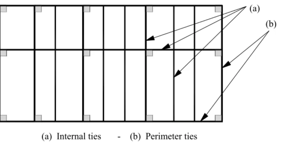
Figure 2-2: Horizontal ties to be adopted for consequences classes 2a and 2b... 28
Figure 2-3: Component model for beam-to-column joint ... 29
Figure 2-4: Typical report for category ‘B’ documents [5]... 32
Figure 3-1: Specific local resistance... 34
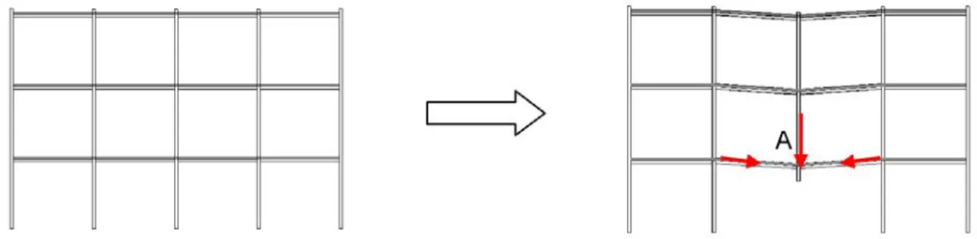
Figure 3-2: Alternate load path by redistribution of internal forces... 34
Figure 3-3: Global strategy followed within this project ... 35
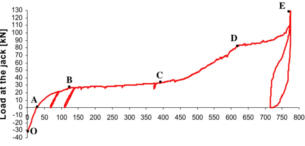
Figure 3-5: Development of the catenary action in the structure – illustration in an “applied load/beam
deflection” curve. ... 36
Figure 3-6: Actual loading in the joint or in the beam end section until failure... 36
Figure 3-7: Undamaged car park frame... 38
Figure 3-8: Damaged frame structure... 38
Figure 3-9: Procedure followed for the analysis of BM 2... 38
Figure 3-10: Localised fire ... 39
Figure 3-11: Fully engulfed fire ... 39
Figure 4-1: Experiments form a unique chain... 42
Figure 4-2: From the actual composite building to the tested substructure... 43
Figure 4-3: 3D view of the designed building and representation of the main frames... 44
Figure 4-4: Static scheme considered for the main frame design... 44
Figure 4-5: Slab cross section... 45
Figure 4-6: Composite beam cross section... 45
Figure 4-7: Distribution of the studs along the composite beam length... 45
Figure 4-8: External steel joint configuration ... 45
Figure 4-9: Geometrical properties of the end-plate ... 45
Figure 4-10: Internal composite joint configuration... 46
Figure 4-11: Comparison of behavioural curves for different types of failure modes ... 47
Figure 4-12: Examples of considered load cases ... 48
Figure 4-13: Deformed shape at collapse and load multiplier-deflection curve obtained through the non-linear analysis ... 48
Figure 4-14: From the actual frame to the tested substructure ... 49
Figure 4-15: Reinforcement and stud layouts ... 50
Figure 4-16: Column support and hinge at the external joints ... 50
Figure 4-17: Lateral restraint influencing the catenary action ... 51
Figure 4-18: Possible positions of column loss for the computation of “K”... 51
Figure 4-19: Symmetric response of the tested substructure... 51
Figure 4-20: Detailed drawing of the substructure test configuration... 51
Figure 4-21: Evolution of the concrete resistance in compression with time... 52
Figure 4-22: Column at the middle simulated by two locked jacks ... 53
Figure 4-23: Application of a vertical load with two vertical jacks ... 54
Figure 4-24: Horizontal restraint simulated by horizontal hollow jacks ... 54
Figure 4-25: Displacement transducers ... 55
Figure 4-26: Rotational transducers ... 55
Figure 4-27: Strain gauges at the IPE140 bottom flange... 55
Figure 4-28: Vertical load at the middle vs. vertical displacement curve ... 56
Figure 4-29: Accentuated cracks in the vicinity of the external composite joints at the formation of the beam plastic mechanism... 56
Figure 4-31: Concrete splitting at the internal composite joint... 57
Figure 4-32: Horizontal displacement vs. horizontal load at the hollow jacks curves ... 57
Figure 4-33: Collapse of the longitudinal rebars in the vicinity of the external composite joints at point “D” of Figure 4.31... 58
Figure 4-34: Yielding spread in the steel components of the external composite joints... 58
Figure 4-35: State of the internal composite joint at point “D” of Figure 4-28... 58
Figure 4-36: Deformation of the specimen at point “E” of Figure 4-28 and horizontal displacement of the specimen at point “E” of Figure 4-28... 58
Figure 4-37: External composite joints at the end of the test ... 59
Figure 4-38: Internal composite joints at the end of the test ... 59
Figure 4-39: Cracks in the welds between the IPE140 profile and the end-plate... 60
Figure 4-40: Rotation of the internal and external composite joints ... 60
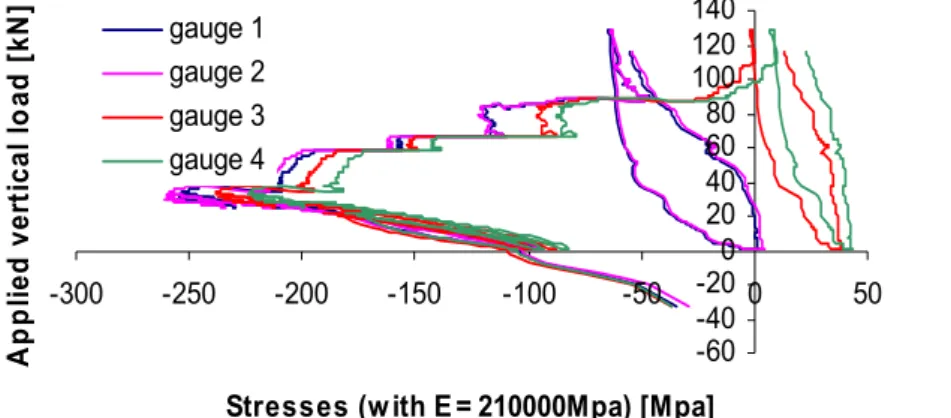
Figure 4-41: Evolution of the stresses in the bottom flange at position A (see Figure 4-27)... 61
Figure 4-42: Evolution of the stresses in the bottom flange at position B (see Figure 4-27)... 61
Figure 4-43: Evolution of the stresses in the bottom flange at position C (see Figure 4-27)... 61
Figure 4-44: Distribution of the cracks in the concrete slab... 62
Figure 4-45: Stage I: Service conditions ... 63
Figure 4-46: Stage II: Column failure ... 63
Figure 4-47: Stage III: Membrane state... 63
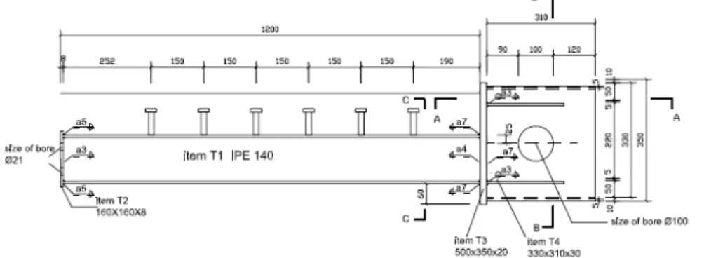
Figure 4-48: Steel beam IPE 140 with the arrangement of the shear studs... 64
Figure 4-49: Cross-section ... 65
Figure 4-50: Layout of the test specimen ... 65
Figure 4-51: Load step 1 (corresponds to stage II Figure 4-46)... 65
Figure 4-52: Load step 2 (corresponds to stage III Figure 4-47)... 65
Figure 4-53: Geometrical properties of the endplate... 66
Figure 4-54: Geometrical dimensions of the composite joint ... 66
Figure 4-55: Crack distribution in the distance of the stirrups ... 67
Figure 4-56: Two big cracks at the corner of the column profile... 67
Figure 4-57: M-phi-curves for the “pure” joint rotation... 68
Figure 4-58: Crack distribution and deformation behaviour for sagging moment... 68
Figure 4-59: Crumbling of the concrete in column section... 68
Figure 4-60: Bearing reactions for the first state of the loading procedure... 69
Figure 4-61: Bearing reactions for the second state of the loading procedure(hogging) ... 69
Figure 4-62: Computed M-N-curves of the composite joint tests ... 69
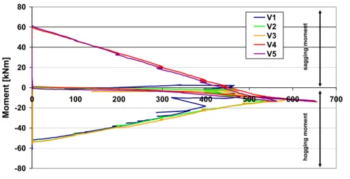
Figure 4-63: Test specimen V1 after failure under M-N exposure (hogging)... 70
Figure 4-64: Test specimen V4 after failure under M-N exposure (sagging) ... 71
Figure 4-65: Arrangement of strain gauges on rebars for test V1 ... 71
Figure 4-66: Arrangement of strain gauges on IPE 140 for tests V1-V5 ... 71
Figure 4-67: Stress Distribution V2 (Pos. A) ... 72
Figure 4-69: Stress Distribution V5 (Pos. A) ... 72
Figure 4-70: Stress Distribution V5 (Pos. B) ... 72
Figure 4-71: Unexpected brittle bolt failure in previous test conducted in Stuttgart [83]... 73
Figure 4-72: Overview of the test specimens S1- S6 ... 74
Figure 4-73: View on the test setup... 75
Figure 4-74: Development of the endplate deformation of test S1 ... 76
Figure 4-75: Development of the endplate deformation of test S3 ... 76
Figure 4-76: Development of the endplate deformation of test S4 ... 76
Figure 4-77: Development of the endplate deformation of test S6 ... 76
Figure 4-78: Moment-phi curves of S1-S4... 78
Figure 4-79: Moment-phi curves of S1-S5-S6 ... 78
Figure 4-80: Check of the rotation capacity and the component deformations of test S1... 79
Figure 4-81: Check of the rotation capacity and the component deformations of test S4... 79
Figure 4-82: Transducer arrangement of T-stub test 6bab ... 80
Figure 4-83: Measured curves of the T-stubs 6bab, 6bb, 6bc ... 80
Figure 4-84: validation of the numerical model ... 81
Figure 4-85: Comparison of deformed shape: experimental - numerical... 81
Figure 4-86: Localisation of membrane effects within the endplate ... 81
Figure 4-87: Geometrical configuration for specimens RCSL (measures in mm)... 83
Figure 4-88: Geometrical configuration for specimens RCRR (measures in mm) ... 84
Figure 4-89: Transducers set-up for specimen RCSL ... 84
Figure 4-90: Transducers set-up for specimen RCRR... 84
Figure 4-91: Results of the tensile tests on rebars. ... 85
Figure 4-92: Crack path for specimen RCSL ... 86
Figure 4-93: Crack path for specimen RCRR ... 86
Figure 4-94: Overall response of specimen RCSL5 (gage length 2687mm)... 87
Figure 4-95: Overall response of specimen RCRR1-2 (gage length 2175 mm)... 87
Figure 4-96: Transducers response (gage length 300 mm) ... 88
Figure 4-97: Effect of reinforcement ratio (gage length 2175 mm) ... 88
Figure 4-98: Comparison between concrete specimens and rebars depending on maximum strain of rebars ... 89
Figure 4-99: Comparison between concrete specimens and rebars depending on strength ratio of rebars ... 90
Figure 4-100: Joint configurations. (measures in mm)... 91
Figure 4-101: Typical transducers’ set-up for tension tests on T-stubs... 92
Figure 4-102: Testing apparatus and transducers’ set-up for tests on T-stubs under axial and shear force. ... 92
Figure 4-103: Bolts’ and flange deformations (on the left) and N-V domain (on the right) for column T-stub specimens of length 256mm. ... 95
Figure 4-105: Test’s results for end-plate T-stub on rigid support... 98
Figure 4-106: Comparison between end-plate T-stub on column and on rigid support. ... 98
Figure 4-107: Comparison between connection on rigid support and T-stub responses... 99
Figure 4-108: Contour map at collapse for connection on rigid support... 99
Figure 4-109: Comparison between connection on rigid support and on the column... 100
Figure 5-1: Comparison of the M-N interaction curves – hogging moment ... 104
Figure 5-2: Comparison of the M-N interaction curves – sagging moment... 104
Figure 5-3: Comparison between the numerical predictions and the experimental results ... 105
Figure 5-4: Comparison of collapse analysis of benchmark model 3 ... 106
Figure 5-5: Comparison of collapse analysis of benchmark model 2 ... 107
Figure 5-6: Denotation code of columns ... 108
Figure 5-7: M-φ interaction of loss a column C-0... 111
Figure 5-8: M-N interaction of loss a column C-0 ... 112
Figure 5-9: M-N interaction of loss a column C-0 ... 113
Figure 5-10: 3-D structure and denotation ... 115
Figure 5-11: Top view on the collapsed structure (93 % of column failure C-0- γ simulated); illustrated with a deformation scale factor of 100 ... 116
Figure 5-12: Middle frame of the global 3-D structure ... 116
Figure 5-13: Front view and top view of the reduced model of the beam 6 and beam 6.1. ... 117
Figure 5-14: Mises-stresses after the second step of the calculation (displacement + compression); illustrated with deformation scale factor 2 ... 117
Figure 5-15: Distribution of the membrane forces developing in the directly affected part ... 118
Figure 5-16: Extracted subsystem ... 118
Figure 5-17: Global model ... 119
Figure 5-18: Affected beams of the global model... 119
Figure 5-19: Simplified substructure... 119
Figure 5-20: Global model ... 120
Figure 5-21: Spring force-displacement curves... 120
Figure 5-22: Simplification of the spring behaviour ... 120
Figure 5-23: Loads of the upper and the lower column during collapse simulation ... 121
Figure 5-24: Resulting loads acting on the substructure ... 121
Figure 5-25: Deformation of the global model and the substructure... 122
Figure 5-26: The eleven levels of the parametric study ... 124
Figure 5-27: Variation of K – Results for “Level 1” subsystem – Mid-span deflection vs. applied load curve ... 126
Figure 5-28: Variation of A – Results for “Level 1” subsystem with K = 3000kN/m– Mid-span deflection vs. applied load c ... 126
Figure 5-29: Variation of I – Results for “Level 9” subsystem with K = 3000kN/m– Mid-span deflection vs. applied load curve ... 126
Figure 5-30: Comparison between the analytical prediction and the experimental results – hogging moment... 129
Figure 5-31: Deformation of the end-plate and the column flange at the end of the bending test ... 129
Figure 5-32 Comparison between the component method prediction and the experimental test result 130 Figure 5-33 Comparison between the component method prediction and the experimental test result 131 Figure 5-34 Comparison of the resistance interaction curves ... 131
Figure 5-35 Distribution of the loads within the bolt rows at point A and point E of Figure 114 ... 132
Figure 5-36 Substructure to be investigated and definition of the main parameters ... 133
Figure 5-37 Comparison between the analytical predictions and the experimental result ... 134
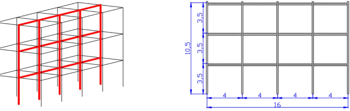
Figure 5-38: Main dimensions and loads of the main frame... 135
Figure 5-39: Main dimension of the structure in transversal direction ... 135
Figure 5-40: Cross-sections of the members ... 135
Figure 5-41: Cross-section of the composite beam over total length ... 135
Figure 5-42: Dead Load ... 136
Figure 5-43: Wind Load ... 136
Figure 5-44: Calculation of the fully functional structure... 137
Figure 5-45: Calculation of the damaged structure ... 137
Figure 5-46: Analysis of the limit load factors of the damaged system (horizontal load) ... 138
Figure 5-47: Analysis of the limit load factors of the damaged system (vertical load)... 138
Figure 5-48: Comparison of the normal force diagram in the columns (damaged system) ... 139
Figure 5-49: Comparison of the M-N-interaction in the columns (damaged system)... 139
Figure 5-50: Location of the calculated Φj in Table 5-10 ... 140
Figure 5-51: Required joint rotation inner composite joint... 140
Figure 5-52: Required joint rotation external steel joint ... 140
Figure 5-53: Joint rotations extract of a composite sway-frame with partial-strength joints ... 141
Figure 5-54: Moment distribution extract of a composite sway-frame with partial-strength joints... 141
Figure 5-55: Development of plastic panel mechanism of sway frames with semi-rigid joints ... 142
Figure 5-56: Influence of the capacity Mpl of the joint to the limit load factor... 142
Figure 5-57: Influence of the capacity Mpl of the joint to the limit load factor... 142
Figure 5-58: Influence of the column profile to the limit load factor... 143
Figure 5-59: Transpolis-General view... 144
Figure 5-60: Transpolis-Detail ... 144
Figure 5-61: Thermal analysis - Beam HD400x314 ... 144
Figure 5-62: Thermal analysis - Column HD400x551... 144
Figure 5-63: Loading of the structure (Transpolis) ... 144
Figure 5-64: Geometry of the structural system... 145
Figure 5-65: Deformation of the Structure after 1920 seconds of fire ... 145
Figure 5-66: Deformation of the structure after 7200 seconds of fire... 145
Figure 5-67: Vertical displacement of the node ... 145
Figure 6-2 Analytical prediction of the simplified subsystem response and determination of the
maximum deflection associated to the maximum load to be supported... 149
Figure 6-3: Fully engulfed fire ... 151
Figure 6-4: Localised fire ... 151
Figure 6-5: Detailing rules for seismic rebars in interior and exterior joints ... 152
Figure 6-6: Coupling beam framing into a wall (on the left) and beam-to-column connection (on the right) ... 153
List of tables
Table 4-1: Mechanical properties of the external steel joints... 46Table 4-2: Mechanical properties of the internal composite joints ... 46
Table 4-3: Bearing capacities of the joints (hogging moment) acc. EC 4 Part 1-1 ... 66
Table 4-4: Bearing capacities of the joints (sagging moment) acc. EC 4 Part 1-1... 67
Table 4-5: Overview about the bearing capacity of the steel joints tests ... 77
Table 4-6: Comparison of the bearing capacities and rotations of the joints S1-S5-S6 ... 78
Table 4-7: Comparison of the bearing capacities and deformations of the T-stub tests 6bab-6bb-6bc .. 80
Table 4-8: Test results for reinforced concrete specimens ... 86
Table 4-9: Comparison between deformation capacities of concrete specimens and of bare rebars. ... 88
Table 4-10: Test results for the CS joint. ... 93
Table 4-11: Test results for the SJ joints. ... 94
Table 4-12: Test’s results for column T-stub specimens under axial and shear force... 96
Table 4-13: Test’s results for the connection on rigid support... 99
Table 4-14: Test’s results for the complete joints. ... 100
Table 4-15: Requirements for joint components to ensure a ductile joint behaviour... 102
Table 5-1: “Collapse” factor... 109
Table 5-2: Load case combinations... 113
Table 5-3: Internal loads and deformations under different loads when the simulation of loss of column C-0 was completed. ... 114
Table 5-4: Main properties of the studied levels ... 125
Table 5-5: Key values obtained experimentally and through the new prediction approach... 129
Table 5-6: Key values obtained experimentally and through the new prediction approach... 130
Table 5-7: Resistance of the composite beams and composite joints... 136
Table 5-8: Comparison of the limit load factors of the undamaged system... 138
Table 5-9: Comparison of the limit load factors of the damaged system... 139
Table 5-10: Joint rotations at the inner and external joints just before collapse of the frame... 139
List of references
Own references (as outcome of the project)
[1] BALDASSINO, N., ZANDONINI, R.: Experimental Study on the Behaviour of Steel and Concrete Joint Components in Large Displacement Field, Proceedings of the 2AESE
2007-Second International Conference on Advances in Experimental Structural Engineering, Vol. 1, Shanghai, China, 4-6 December, Tongji University, pp. 73-81, 2007.
[2] BALDASSINO, N., ZANDONINI, R.: Component Tests for Characterisation of Composite Steel-Concrete Joints, Proceedings of the SEMC 2007-Recent Developments in Structural Engineering, Mechanics and Computations, vol. 1, Cape Town, South Africa, 10-12 September, Millpress Science Publishers, pp. 1127-1132, 2007.
[3] BALDASSINO, N., SEEMA, ZANDONINI, R.: Alcune Considerazioni sulla Robustezza Strutturale. Atti XXI Congresso C.T.A, Catania, Italia, 1-3 Ottobre 2007, Dario Flaccovio Editore, pp. 17-24, 2007.
[4] BALDASSINO, N., ZANDONINI, R.: Comportamento di collegamenti in strutture composte soggette a carichi eccezionali, Atti del convegno Sperimentazione su materiali e strutture, Venezia, Italia, 6-7 dicembre, Dca-IUAV, pp. 337-346, 2006.
[5] BALDASSINO, N., SEEMA, ZANDONINI, R.: Database on Robust Systems, Document No: Robustness - Report - TRENTO - 001- June 2007
[6] BALDASSINO, N., ZANDONINI, R.: Experimental Tests on Steel and Concrete Beam-to-Column Joint Components, Internal report for the RFCS project RFS-CR-04046 “Robust structures by joint ductility”, Document No:ROBUSTNESS-Report-TRENTO-002, University of Trento, 2007.
[7] CORSI, S.: Giunti trave-colonna in acciaio in grandi spostamenti, Master Thesis, in Italian, Università degli Studi di Trento, 2006.
[8] DEMONCEAU, J.F.; JASPART J.P.: Predesign of the substructure to be tested at the University of Liège. Internal report for the RFCS project RFS-CR-04046 “Robust structures by joint ductility”, Document No:ROBUSTNESS-Report-ULg-001, Liège University, January 2006
[9] DEMONCEAU, J.F.; JASPART J.P.: From the actual composite building to the tested substructure. Internal report for the RFCS project RFS-CR-04046 “Robust structures by joint ductility”, Document No:ROBUSTNESS-Report-ULg-002, Liège University, January 2006 [10] DEMONCEAU, J.F.; JASPART J.P.: Loss of a column in an office or residential building frame
– First investigations of the steel “two-beams” system. Internal report for the RFCS project RFS-CR-04046 “Robust structures by joint ductility”, Document No:ROBUSTNESS-Report-ULg-003, Liège University, May 2006
[11] DEMONCEAU, J.F.; JASPART J.P.: Experimental test simulating the loss of a column in a composite building – Liège University. Internal report for the RFCS project RFS-CR-04046 “Robust structures by joint ductility”, Document No:ROBUSTNESS-Report-ULg-004, Liège University, September 2006
[12] DEMONCEAU, J.F.; JASPART, J.P.: Detailed drawings of the substructure to be tested in Liège. Internal report for the RFCS project RFS-CR-04046 “Robust structures by joint ductility”, Document No:ROBUSTNESS-Report-ULg-005, Liège University, January 2006
[13] DEMONCEAU, J.F.; LUU, H.N.N.; JASPART, J.P.: Recent investigations on the behaviour of buildings after the loss of a column, ICMS conference, Poiana Brasov, September 20 – 22, 2006. [14] DEMONCEAU, J.F.; JASPART, J.P.: Experimental investigations on the behaviour of a
composite frame after the loss of a column, ICSAS 2007, 6th International Conference on Steel and Aluminium Structures, Oxford, July 24 – 27, 2007.
[15] DEMONCEAU, J.F.; JASPART, J.P.: Robustness of structures – behaviour of composite joints, International Workshop on Connections in Steel Structures 2008, Chicago, 23 – 25 June 2008 (Abstract accepted)
[16] DEMONCEAU, J.F.; JASPART, J.P.: Development of membrane effects in frame beams: experimental and analytical investigations, EUROSTEEL 2008 “5th International conference on Steel and Composite Structures”, 3 – 5 September 2008 (Abstract accepted).
[17] HOIER, A.: Modellierung eines geschraubten Stahlknotenanschlusses mit Finiten Elementen. Diploma Thesis, Universität Stuttgart, Mitteilung des Instituts für Konstruktion und Entwurf Nr. 2007-8X, 2007 (in German)
[18] JASPART, J.P.; DEMONCEAU, J.F.; LUU, H.N.N.: Numerical, analytical and experimental investigations on the response of steel and composite buildings further the loss of a column, Colloquium on structural design of constructions subjected to exceptional or accidental actions, Brussels, Belgium, 9 April 2008.
[19] JASPART, J.P.; DEMONCEAU, J.F.: Contribution to the derivation of robustness requirements for steel and composite structures, ICASS 2007 “Advances in steel structures”, 5 – 7 December 2007, Singapore.
[20] KUHLMANN, U.; JASPART, J.-P.; VASSART, O.; WEYNAND, K.; ZANDONINI, R.: Robust structures by joint ductility. Proceedings of IABSE Symposium Budapest 2006, Vol. 92, 2006 [21] KUHLMANN, U.; RÖLLE, L.: Experimental tests on composite joints with biaxial loading –test
results. Internal report for the RFCS project RFS-CR-04046 “Robust structures by joint ductility”, Document No: ROBUSTNESS-Report-USTUTT-001, 2007
[22] KUHLMANN, U.; RÖLLE, L.: Evaluation of the experimental tests on composite joints under biaxial loading. Internal report for the RFCS project RFS-CR-04046 “Robust structures by joint ductility”, Document No: ROBUSTNESS-Report-USTUTT-002, 2007
[23] KUHLMANN, U.; RÖLLE, L.: Experimental tests on steel joints and evaluation of the test results. Internal report for the RFCS project RFS-CR-04046 “Robust structures by joint ductility”, Document No: ROBUSTNESS-Report-USTUTT-003, 2007
[24] KUHLMANN, U.; RÖLLE, L.: Numerical Simulation of the event “Loss of a bracing in a car park”. Internal report for the RFCS project RFS-CR-04046 “Robust structures by joint ductility”, Document No: ROBUSTNESS-Report-USTUTT-004, 2007
[25] KUHLMANN, U.; RÖLLE, L.: Numerical investigations for benchmark model 1 “Loss of a column in an office building”. Internal report for the RFCS project RFS-CR-04046 “Robust structures by joint ductility”, Document No: ROBUSTNESS-Report-USTUTT-005, 2007
[26] KUHLMANN, U.; RÖLLE, L.; JASPART, J.-P.; DEMONCEAU, J.-F.: Robustness-Robust structures by joint ductility. Proceedings of COST C 26 Workshop Prague, 2007
[27] KUHLMANN, U.; RÖLLE, L.: Redundant and Robust Frame Structures by Joint Ductility. COST TU 0601 Workshop Zurich, February 2008
[28] RÖLLE, L.: Redundant and Robust Frame Structures by Joint Ductility. 7th fib International PhD Symposium in Civil Engineering Stuttgart, September 2008 (Abstract accepted)
[29] ROBUSTNESS/ALL-01: RFS-CR-04046 Six-monthly technical report. Reporting period 07/2004-12/2004.
[30] ROBUSTNESS/ALL-02: RFS-CR-04046. Six-monthly technical report. Reporting period 01/2005-06/2005.
[31] ROBUSTNESS/ALL-03: RFS-CR-04046. Mid-term technical report. Reporting period 07/2005-12/2005.
[32] ROBUSTNESS/ALL-04: RFS-CR-04046. Six-monthly technical report. Reporting period 01/2006-06/2006.
[33] ROBUSTNESS/ALL-05: RFS-CR-04046. Six-monthly technical report. Reporting period 07/2006-12/2006.
[34] ROBUSTENESS: RFS-CR-04046. Design Guidance. Document No: ROBUSTNESS-Handbook-001, 2007
[35] STEFANI, M.: Tension stiffenenig in elementi in cemento armato in regime di grandi spostamenti, Master Thesis, In Italian, Università degli Studi di Trento, 2006.
[36] WEYNAND, K.; ZILLER, C.; BUSSE, E.; LENDERING, M.: System Calibration - Benchmark model 3, Internal report for the RFCS project RFS-CR-04046 “Robust structures by joint ductility”, Document No: ROBUSTNESS-Report-PSP-001, Aachen 2007
[37] WEYNAND, K.; ZILLER, C.; BUSSE, E.; LENDERING, M.: Parametric studies “Loss of a column”, Internal report for the RFCS project RFS-CR-04046 “Robust structures by joint ductility”, Document No: ROBUSTNESS-Report-PSP-002, Aachen 2007
[38] WEYNAND, K.; ZILLER, C.; BUSSE, E.; LENDERING, M.: Calibration of the simplified substructure, Internal report for the RFCS project RFS-CR-04046 “Robust structures by joint ductility”, Document No: ROBUSTNESS-Report-PSP-003, Aachen 2007
Other references
[39] ABAQUS/CAE, User’s manual Version 6.5 Documentation, ©ABAQUS, Inc. 2004. [40] ANSYS User’s manual. ANSYS Mechanical Solutions Release 11.0, 2007
[41] AGARWAL, J.; ENGLAND, J.; BLOCKLEY, J. and D.: Vulnerability Analysis of Structures, Structural Engineering International, IABSE, Vol. 16 (2), pp. 124-128, 2006
[42] AHMED, B.; LI, T.Q.; NETHERCOT, D.A.: Design of Composite Fin-plate and Angle Cleated Connections. Journal of Constructional Steel research. vol. 41(1). pp. 1-29, January 1997.
[43] ANDERSON, D.: Composite steel-concrete joints in frames for buildings: Design provisisons. COST C1 – Semi-rigid behaviour of civil engineering structural connections, Luxembourg, 1999. [44] AS/NZS 1170.0: 2002: “Structural design actions–General principles”, Standards Australia,
Standards New Zealand, 2002 Edition.
[45] AS/NZS 1170.0 Supplement 1: 2002 “Structural design actions–General principles– Commentary”. Standards Australia, Standards New Zealand, 2002 Edition.
[46] BANIOTOPOULOS C.C. & WALD F, (eds) (2000). The Paramount Role of Joints onto the Reliable Response of Structures, NATO Science Series. Dordrecht. Kluwer Academic Publishers. [47] BENUSSI, F.; NETHERCOT, D. A.; ZANDONINI, R.: Experimental Behaviour of Semi-Rigid
Connections in Frames”, The 3rd Int. Workshop on Connections in Steel Structures, Trento, Italy, 1995.
[48] Building Regulations. Approved Document A. The building regulations 1991. Structure 1992 Edition.
[49] Building Regulations 2000 – Approved Document A – Structures, Approved Document A – Amendments 2004 – The Stationary Office, 2004.
[50] BURSI, O.S.: Elastic-Plastic Modelling of Structural Fasteners for Steel Bracing Connections. Journal of Constructional Steel Research. vol. 30 (1), pp. 13-38, 1994.
[51] BURSI, O.S.; FERRARIO, F.; FONTANARI, V.: Non-linear Analysis of the Low-cycle Fracture Behaviour of Isolated T-Stub Connections. Computer and Structures. vol. 80 (27-30). pp. 2333-2360, 2002.
[52] CERFONTAINE, F.: Study of the interaction between bending moment and normal force in bolted joints. PhD Thesis. Universitè de Liège, 2004
[53] CORLEY, W.G.: Lessons learned on Improving Resistance of Buildings to Terrorist Attacks, Journal of Performance of Constructed Facilities, Vol. 18 (2), pp. 68-78, 2004.
[54] CORLEY, W.G.: Applicability of Seismic Design in Mitigating Progressive Collapse, Proc. of Workshop on Prevention of Progressive Collapse Multihazard Mitigation, Council of National Institute of Building Sciences, U.S.A.,10-12 July, 2002.
[55] Council of National Institute of Building Sciences, Washington DC (2003). “Prevention of progressive Collapse”. Report on the July 2002 National Workshop and Recommendations for future efforts, multi-hazard mitigation.
[56] COSSFIRE. RFCS Contract N°: RFSR-CT-2006-00028. Connections of steel and composite structures under natural fire conditions. Runtime Periode 07/2006 – 06/2009
[57] DEMONCEAU, J.F.: Steel and composite building frames: sway response under conventional loading and development of membrane effects in beams further to an exceptional event. PhD thesis. University of Liège, June 2008.
[58] DONALD, O.D. (2002). “Review of Existing Guidelines and Provisions Related to Progressive Collapse”. Proc. of Workshop on Prevention of Progressive Collapse Multihazard Mitigation. Council of National Institute of Building Sciences, U.S.A..10-12 July.
[59] ECCS Document N° 111. ECCS Model Code on fire engineering. Technical Committee 3. Brussels 2001
[60] ECCS Document N°109. Design of composite joints for buildings. ECCS Technical Committee 11. Brussels 1999
[61] ECCS Document N°96. Design handbook for braced composite steel-concrete buildings according to Eurocode 4. Profilearbed Recherches, Brussels 2000
[62] ELLINGWOOD, B. R.; DUSENBERRY, D. O. (2005). “Building Design for Abnormal Loads and Progressive Collapse”. Computer-Aided Civil and Infrastructure Engineering. Vol. 20.
[63] EN 1990: Eurocode – Basis of Structural Design, CEN European Committee for Standardization, April 2002.
[64] EN 1991-1-1: Eurocode 1 – Actions on structures – Part 1-1 General Actions – Densities, Self-weight, Imposed loads for Buildings, CEN, 2002
[65] EN 1991-1-4: Eurocode 1 - Actions on structures - Part 1-4: General actions, Wind actions; German version EN 1991-1-4:2005
[66] EN 1991-1-7: Eurocode 1 – Actions on structures – Part 1-7: General Actions - Accidental actions due to impact and explosions, CEN, 2002
[67] EN 1992-1-1: Eurocode 2 – Design of Concrete Structures – Part 1-1: General Rules for buildings. CEN, 2004.
[68] EN 1993-1-1: Eurocode 3 - Design of Steel Structures - Part 1-1: General Rules and Rules for Buildings. CEN, 2005
[69] EN 1993-1-8: Eurocode 3 - Design of Steel Structures - Part 1-8: Design of joints. CEN, 2005 [70] EN 1994-1-1: Eurocode 4 - Design of Composite steel and concrete Structures - Part 1-1: General
Rules and Rules for Buildings. CEN, 2004
[71] EN 1998-1: Eurocode 8 - Design of Structures for Earthquake Resistance, Part 1: General rules, seismic actions and rules for buildings. CEN, 2005
[72] FAELLA, C.; PILUSO, V.; RIZZANO, G.: Structural Steel Semirigid Connections: Theory, Design and Software, CRC Press LLC, Boca Raton, 2000.
[73] FINELG user’s manual: Non-linear finite element analysis software. Version 8.2, July 1999 [74] FRANSSEN, J.-M., PROGRAM SAFIR, Ver. 1.3, User’s Manual, Universite de Liege, Institut du
Genie Civil, Service Ponts et Charpentes, December 1996.
[75] GARCIA, E.M.; DAVISON, B.; TYAS, A.: Analysis of the response of Structural Bolts subjected to rapid rates of loading, Proceedings of the 4th European Conference on Steel and Composite Structures. vol. C. Maastricht, The Netherlands, 8 th-10th June 2005.
[76] GERARDY, J. C.; SCHLEICH, J. B.: Semi-rigid action in steel frame structures, Commission of the European Communities: technical steel research, Report EUR 14427 EN, 1992.
[77] GHOBARAH, A.; OSMAN, A.; KOROL, M.: Behaviour of Extended End-plate Connections under Cyclic Loading. Engineering Structures. vol. 12(1). pp. 15-27, January 1990.
[78] GRIFFITHS, H.; PUGSLEY, A.; SAUNDERS, O.: Report of the Inquiry into the Collapse of Flats at Ronan Point Canning Town, Her Majesty’s Stationery Office, London (UK), 1968.
[79] HUBER, G.; KRONENBERGER, H.J.; WEYNAND, K. (1998). “Representation of Joints in the Analysis of Structural Systems”. Proc. COST CI Conference on Semi Rigid Connections. Liege, September.
[80] JASPART, J.P.: Etude de la Semi-Rigidite des Noeuds Poutre-Colonne et son Influence sur la Resistance et la Stabilite des Ossatures en Acier, Ph.D. Thesis, University of Liege, Belgium, 1991.
[81] JASPART, J. P.; STEENHUIS, M.; ANDERSON, D., (1998). “Characterisation of the Joint properties by means of the Component Method”. Proc. COST CI Conference on Semi Rigid Connections. Liege. September.
[82] KRAUTHAMMER, T.; HALL, R. L.; WOODSON, S. C.; AYLOT, J. T.; HAYES, J. R., (2002). “Development of Progressive Collapse Analysis Procedure and Condition Assessment for Structures”. Proc. of Workshop on Prevention of Progressive Collapse Multihazard Mitigation. Council of National Institute of Building Sciences. U.S.A..10-12 July.
[83] KUHLMANN, U.; SCHÄFER, M.: Innovative verschiebliche Verbundrahmen mit teiltragfähigen Verbundknoten. Schlussbericht, Research Project by order of the Studiengesellschaft Stahlanwendung e.V., Nr. P505 (2003).
[84] LAHMEYER, J. Untersuchung an verschieblichen Verbundrahmenelementen mit teiltragfähigen Knoten. Diploma thesis. Universität Stuttgart, Mitteilung des Institutes für Konstruktion und Entwurf 2003-5X (2003)
[85] LE CHUYEN, N. K.: Analytical prediction of the lateral restraint influencing the development of the membraner forces. Master Thesis. Universitè de Liège, 2005
[86] LEROY, R.: Evaluation of the rotation capacity of joints in steel and composite structures. Diploma Thesis. Universitè de Liège, 2005
[87] LIU, R., DAVISON, J. B., TYAS A. (2005). “A study of Progressive Collapse in Multistorey Buildings”. Proc. of the 2005 Structures Congress and Forensic Engineering symposium, New York.
[88] LUU, N. N. H.: Structural response of steel and composite building frames further to an impact leading to the loss of a column. PhD thesis presented at the University of Liège, August 2008. [89] MAES, M. A.; FRITZSONS, K. E.; GLOWIENKA, S.: Structural Robustness in the Light of Risk
and Consequence Analysis, Structural Engineering International, Vol. 16 (2), pp. 101-107, May 2006.
[90] MARECHAL, D.: Evaluation of the rotation capacity of joints in steel structures. Diploma Thesis. Universitè de Liège, 2004
[91] MAZZOLANI, F.M.; PILUSO, V.: Theory and Design of Seismic Resistant Steel Frames, E&FN SPON, an Imprint of Chapman & Hall, London, 1996.
[92] Model Code 1990, Bulletin d’information n 213/214, CEB-FIP, Thomas Telford, London, 1993. [93] MOORE, D. B.: The UK and European Regulations for Accidental Actions, Proc. of Workshop
on Prevention of Progressive Collapse Multihazard Mitigation, Council of National Institute of Building Sciences, 10-12 July, 2002.
[94] PRECIOUS. RFCS Contract N°: RFSR-CT-2003-00034. Prefabricated composite beam-to-concrete filled tube or partially reinforced-beam-to-concrete-encased column connections for severe seismic and fire loadings. Runtime Periode 09/2003 – 08/2006
[95] PUHALI, R.; SMOTLAK, I.; ZANDONINI, R.: Semi-Rigid Composite Action: Experimental Analysis and a Suitable Model. Journal of Constructional Steel Research, vol. 15 (1/2), pp. 121-151, 1990.
[96] SCHÄFER, M.: Zum Rotationsnachweis teiltragfähigen Verbundknoten in verschieblichen Verbundrahmen. Dissertation. Universität Stuttgart, Mitteilung des Institutes für Konstruktion und Entwurf Nr. 2005-1, (2005)
[97] SEDLACEK, G.; WEYNAND, K; KLINGHAMMER, R.; HÜLLER, V.: Typisierte Anschlüsse im Stahlhochbau. Deutscher Stahlbau-Verband DSTV Stahlbau Verlag- und Service GmbH. “. Auflage 2 (Band 2), November 2002.
[98] Seismic Provisions for Structural Steel Buildings. Part 1: Provisions, American Society of Civil Engineers (AISC), 2002 Edition.
[99] Seismic Provisions for Structural Steel Buildings. Part 2: Commentary, American Society of Civil Engineers (AISC), 2002 Edition.
[100] SOFISTIK user’s manual Star 2, Non-linear frame system analysis software. Version 14.13, 2005 [101] STAROSSEK, U.: Progressive Collapse of Structures: Nomenclature and Procedure, Structural
Engineering International, IABSE, Vol. 16 (2), pp. 113-117, 2006.
[102] STEENHUIS, C.M., HERWIJNEN Van F, SNIJDER, H.H. (2000). “Safety Concepts for Ductility of Joints”. International AISC/ECCS workshop on Connections in Steel Structures IV. Roanoke. October 22-25.
[103] SWANSON, J.A.; LEON, R.T.: Bolted Steel Connections: Tests on T-Stub Components. Journal of Structural Engineering, Vol. 126(1). pp. 50-56, 2000.
[104] TRONG TRI, N.: Analytical study of cantenary action in beams further to the accidental loss of a column in a steel building frame. Master Thesis. Universitè de Liège, 2006
[105] VLASSIS, A.G.; IZZUDIN, B.A.; ELGHAZOULI A.Y.; NETHERCOT, D.A.: Design Oriented Approach for Progressive Collapse Assessment of Steel Framed Buildings, Structural Engineering International, IABSE, Vol. 16 (2), pp. 129-136, 2006.
[106] www.connectionprogram.com
[107] ZOETEMEIJER, P.: A design method for the tension side of statically loaded, bolted beam-to-column connections, Heron Stevin-Laboratory, vol. 20 (1), The Netherlands, pp.3-59, 1974. [108] ZOETEMEIJER, P.: “Summary of the Research on Bolted Beam to Column Connections”. Delft