HAL Id: inria-00587862
https://hal.inria.fr/inria-00587862
Submitted on 21 Apr 2011
HAL is a multi-disciplinary open access
archive for the deposit and dissemination of
sci-entific research documents, whether they are
pub-lished or not. The documents may come from
teaching and research institutions in France or
abroad, or from public or private research centers.
L’archive ouverte pluridisciplinaire HAL, est
destinée au dépôt et à la diffusion de documents
scientifiques de niveau recherche, publiés ou non,
émanant des établissements d’enseignement et de
recherche français ou étrangers, des laboratoires
publics ou privés.
SensLAB Very Large Scale Open Wireless Sensor
Network Testbed
Clément Burin Des Rosiers, Guillaume Chelius, Eric Fleury, Antoine
Fraboulet, Antoine Gallais, Nathalie Mitton, Thomas Noël
To cite this version:
Clément Burin Des Rosiers, Guillaume Chelius, Eric Fleury, Antoine Fraboulet, Antoine Gallais, et
al.. SensLAB Very Large Scale Open Wireless Sensor Network Testbed. Proc. 7th International
ICST Conference on Testbeds and Research Infrastructures for the Development of Networks and
Communities (TridentCOM), Apr 2011, Shanghai, China. �inria-00587862�
Very Large Scale Open Wireless Sensor Network Testbed
Cl´ement Burin des Rosiers2
, Guillaume Chelius2,1,5
, Eric Fleury1,2,5
, Antoine
Fraboulet3,2,5, Antoine Gallais4, Nathalie Mitton2, and Thomas No¨el4
1
ENS de Lyon, BP 7000 69342 Lyon Cedex 07 - France
2
INRIA
3
INSA de Lyon, 69621 Villeurbanne Cedex, France
4
Universit´e de Strasbourg, 67081 Strasbourg Cedex, France
5
Universit´e de Lyon
Abstract. This paper presents a precise description of SensLAB: Very
Large Scale Open Wireless Sensor Network Testbed that has been devel-oped and deployed in order to allow the evaluation of scalable wireless sensor network protocols and applications. SensLAB’s main and most important goal is to offer an accurate open access multi-users scientific tool to support the design, development, tuning, and experimentation of real large-scale sensor network applications. The SensLAB testbed is composed of 1024 nodes and it is distributed among 4 sites. Two sites offer access to mobile nodes. Every sensor node is also able to be config-ured as a sink node and can exchange data with any other sink node of the whole SensLAB testbed (locally or remotely) or any computer on the Internet. The hardware designed on purpose and software architectures that allow to reserve, configure, deploy embedded software, boot wireless sensor nodes and gather experimental data and monitoring information are described in details. We also present short demonstration examples to illustrate the use of the SensLAB testbed.
Key words: Wireless Sensor Network, Testbed, Radio, Network, Monitoring
1 Introduction
Wireless sensor networks (WSN) have emerged as a premier research topic. In the industrial domain, wireless sensor networks are opening up machine-to-machine (M2M) communications. The M2M market comprises the technology that sup-ports wired or wireless communications among devices. When looking at the M2M market, a global trend is towards interconnecting M2M modules through wireless network technologies. Considering this major trend in the wireless M2M market, several challenges arise both for short-term and long-term evolution and marketing possibilities of these technologies. However, due to their massively dis-tributed nature, the design, implementation, and evaluation of sensor network
applications, middleware and communication protocols are difficult and time-consuming tasks. It appears strategic and crucial to offer to researchers and developers accurate software tools, physical large scale testbeds to benchmark, tune, and optimize their applications and services.
As proposed by initiatives in Europe and worldwide2
, enabling an open, general-purpose, and sustainable large-scale shared experimental facility like “open wireless multi-users experiment facility testbeds”, will foster the emergence of the Future Internet. Simulation is an important phase during the design and the provisioning step. There is an increasing demand among researchers and production system architects to access testbed resources they need to conduct their experiments.
In order to design robust applications that have to be deployed under real-world conditions, developers need appropriate tools, methods, experimental fa-cilities for testing and managing their large scale wireless sensor network
appli-cations. In this document, we introduce SensLAB3
, an open access multi-user WSN testbed. SensLAB is strategic, as it gives people wanting to assess new sensor technologies the tools to quickly deploy their experiments, evaluate, and analyze the results produced by the testbed facilities. As such, it lowers the entry cost to experimentation, often considered as a complex and heavyweight activity, with no extra management burden, accelerating proof-of-concept evaluation and competitiveness.
The remainder of this document is organized as follows: Section 2 describes the general design requirements mandatory to insure the success of a large scale wireless sensor network testbed. We describe in Section 4 and Section 5 the various hardware and software modules and components developed within the SensLAB context. Section 6 presents some experimental results using the infras-tructure and facilities offered by SensLAB.
2 Design Requirements and Methodology
2.1 Context and State-of-the-Art
Wireless sensor networks are becoming a strategic domain of research and raise a large amount of new challenges, attracting the worldwide community in several domains of computer sciences but also requiring interdisciplinary researches. However, a gap still remains in terms of experimental results. One barrier to the widespread use of wireless sensor networks is the difficulty of coaxing reliable information from nodes whose batteries are small, whose wireless medium is sporadic and vulnerable, whose embedded software may contain bugs and errors, or whose connectivity is intermittent. It is thus very important to conduct in situ experiments and researches to better understand the characteristics and compensate for some of these flaws and reach the state of maturity to make
2
EU’s Fire, US’s GENI, Japan’s Akari, AsiaFI
3
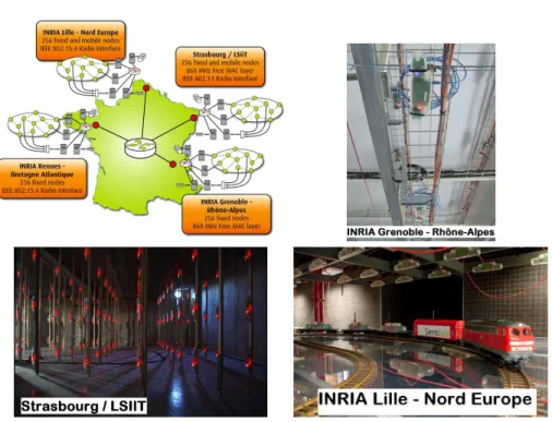
Fig. 1. SensLAB testbed is composed of four distributed wireless sensor networks interconnected by Internet (1024 nodes in total). The four sites form a unique testbed, every sensor node is potentially a sink node, able to communicate and exchange data with any other node. Mobile nodes are available on 2 sites (Strasbourg and Lille) thanks to several toy electric trains tuned to be remotely controllable and to supply power to the nodes.
them practical. Unfortunately, the development and testing of real experiments engaging distributed systems like sensor networks quickly become a nightmare if the number of nodes exceeds a few dozens. Developing and deploying a general purpose open wireless sensor network testbed, accessible to multiple users raises several challenges that are not present in wired network (Emulab [14], OneLab & PlanetLab [11]) or even wireless mesh networks (Orbit [12]). The daunting logistical challenge of experimenting with thousands of small battery-powered nodes is the key factor that has greatly limited the development of this field. The main reasons for this very high complexity come from a variety of factors: – Sensors are small devices with very limited interface capacities, mainly in
terms of debugging and friendly programming interface.
– Software deployment, node re-programming, and debugging are traditionally done through dedicated interfaces (e.g., JTAG) which require the connection of the device to a dedicated PC and thus the individual manipulation of each sensor nodes.
– Sensors are generally powered by a battery which also implies human inter-ventions. Each intervention is time consuming, error prone and not really gratifying.
– There is a crucial lack of development tools and software environments that may help the development of applications and their configuration.
State of the art We review here some well known projects in the domain of
sensor networks and we try to summarize the state of the art related to large scale WSN.
CitySense4
consists of a set of nodes deployed on rooftops and streetlights around Cambridge/UK. Currently there are 25 nodes deployed outside and an-other 32 nodes deployed as part of an indoor testbed. Citysense is a mesh of PCs with high power radios. It does not allow testing application on small devices constrained by energy, memory, CPU, etc. ORBIT [12] focuses on the creation of a large-scale wireless network testbed to facilitate a broad range of experimental research on next-generation protocols and application concepts. The ORBIT’s philosophy is similar to SensLAB but it’s dedicated to IEEE 802.11 like networks and not to constrained and embedded sensor networks.
There exist WSN testbeds like moteLab5
, Kansei6
, WASAL7
or TWIST [6] but they do not target the same objectives as SensLAB. In moteLab, an early example, nodes run the TinyOS operating system and are programmed in the NesC programming language. Kansei offers hybrid simulation engine for simulat-ing substantially larger arrays ussimulat-ing testbed hardware resources. Despite havsimulat-ing dedicated wired back-channels, neither WASAL, TWSIT nor Kansei provide any accurate and real time feedback monitoring measure on the energy consumption of the nodes. Testbeds do not offer radio instrumentation and/or noise injection. The testbeds does not offer the possibility to study hierarchical protocols in or-der to interconnect sensor network clouds through the Internet. A last important drawback is that they all use IEEE 802.15.4 MAC layer and most of them impose TinyOS. Two problems arise. First, fixing the MAC layer to only IEEE 802.15.4 nips in the bud any research that targets at the optimization/improvement of MAC layers. Second, imposing a specific OS (like TinyOS) constrains applica-tions to use a dedicated OS that is neither really optimized nor efficient in terms of energy consumption and clock frequency optimization for all kind of
applica-tions. Recently, the WISEBED8
project shows the ambition to federate several WSN testbeds in order to establish a European wireless sensor network. It seems that application should be developed by using a specific API dedicated to the WISEBED platform. A great benefit of the WISEBED project is the release of Wiselib, an algorithm library for sensor networks (localization, routing) [2].
4 http://www.citysense.net/ 5 http://motelab.eecs.harvard.edu/ 6 http://ceti.cse.ohio-state.edu/kansei/ 7 http://wasal.epfl.ch/ 8 http://www.wisebed.eu/
2.2 Requirements
We propose to eliminate some of the problems listed above by operating SensLAB as an open research facility for academic and industrial groups who want to ex-periment with novel distributed sensing architectures by providing a research infrastructure for networking sensors and by offering a large scale instrument for the exploration of sensor network issues in reproducible experimental condi-tions. The platform is generic, open and flexible: it means that a user is able to remotely (web access) access and deploy his/her applications without any kind of restrictions on the programming language, on the programming model or on the OS that he/she must use. The testbed should be scalable, cover a large spectrum of sensor network applications and target several kinds of end users.
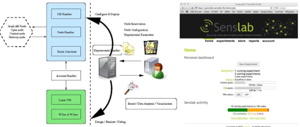
Fig. 2. Simplified view of the platform usage/services (left). SensLAB portal (right).
Figure 2 gives an overview of the testbed services. Once logged on the main portal, a user can describe his/her experiments in terms of node number, sensor & radio characteristics, topology considerations, experimentation time. The ex-periment description also specifies all the firmwares that need to be flashed. The user is free to develop his/her application with TinyOS or any other high level component oriented language/OS down to low level assembly. To help the user in developing his/her application, a virtual machine is setup with all the devel-opment tools and chains preconfigured (cross compilation chains, OS, drivers, communication libraries). The user can also access and use higher level develop-ment and prototyping tools (like cycle accurate hardware platform simulator [5] or more conventional radio accurate wireless network simulator [3]). Once this main task is done, the experiment is submitted to the global reservation sched-uler. Once the time arrived, all the nodes are reserved, configured automatically (firmware is flashed, monitoring is configured, output result databases are cre-ated. . . ) and the experiment is launched. The user keeps an on-line access to his/her nodes (either by the web or by a command line shell). If required by the user, every node could be configured as a sink and be able to transmit data
towards any application on the Internet and thus to any other sink node. When an experiment is launched, specific SQL tables related to the experiment are cre-ated. All monitoring data collected during an experiment are stored in tables to support subsequent analysis. The user is thus able to perform postmortem anal-ysis but the system also provides online data analanal-ysis services (OLAP/ On-Line analytical Processing).
To reach the main objectives of the testbed in terms of scalability, open ac-cess flexibility, reliability, monitoring accuracy and reproducibility, strong efforts and developments are required, both on the hardware and software sides. The hardware design of the SensLAB nodes must satisfy several strong requirements: (i) reliable access to the nodes in order to perform operations such as a re-set or code flashing whatever the state of the sensor node or the software it is running. Users must have a full control in terms of OS, software deployment on each sensor node (which potentially implies tons of erroneous codes!); (ii) non intrusive and application transparent real time monitoring of the sen-sor nodes. The external monitoring (i.e., totally independent from the deployed user application code) will include precise and real-time access to fundamental parameters such as energy consumption and radio activity on a per node ba-sis; (iii) security and data integrity between consecutive experiments on the same set of nodes; (iv) real time control of the experiments by providing a set of commands that may influence an application environment (e.g., turn sensor nodes on/off to mimic crashes, emit radio noise by sending fake data in order to tamper with transmissions, modify the monitoring frequency parameters); (v) if experimental results / validations are important, they should be reproducible.
Repeatability is a crucial issue, especially when dealing with wireless sensor
network operating in an ’event’ based programming paradigm.
3 Main Elements of SensLAB
We will describe more precisely all the different elements of SensLAB in the two following sections. A first schematic view of the global architecture is depicted on Figure 3. Each service is replicated on each site in order to be fault tolerant (DNS for users virtual machines, LDAP for authentication. . . ). Figure 5 gives a very precise view of a SensLAB node, and Figure 6 details all the software components deployed on each site.
4 SensLAB Hardware Components and Infrastructures
All the requirements listed in Section 2.2 have a strong impact on the hardware and on the architecture needed to support the testbed and handle all user exper-iments. More precisely, the SensLAB hardware infrastructure consists of three main components:
1. The open wireless sensor node is made available to the user during his/her experimentation. This node is totally open and the user is granted a
Fig. 3. Architecture of the distributed platform. The four sites are connected via a VPN and the services (file system, LDAP, DNS. . . ) are distributed for fault tolerant operations.
full access to the memory. This implies that he/she could load and run any operating system. This feature is handled using a remote access to reboot and (re)load any firmware on any node.
2. The full SensLAB node that encompasses the open node also includes a gateway and a closed wireless node. The SensLAB gateway offers a connex-ion to the global infrastructure to control and monitor the open node. The gateway also handles the open node serial link if the node is set to be a sink node. The closed node is the same as the open one and it is only used to interact, passively or actively with the open node.
3. The global networking backbone that provides power and connectivity to all SensLAB nodes and guaranties the out of band signal network needed for command purposes and monitoring feedback.
4.1 Open Wireless Sensor Node
The choice of the wireless sensor node is a crucial task since it is related to the broad range of wireless sensor network problems that might be anticipated over the next 4-8 years. The current trend for wireless sensors nodes is geared toward a common architecture based on off the shelf 16-bit micro-controllers. We thus clearly target low power wireless sensor nodes constrained in memory
and energy like existing products already on the market9
. In order to meet with the requirements in terms of energy monitoring, reproducibility, we need to master the architecture and a solution has been to design our own board in order to include all control signals and thus guarantee a reliable control and
9
feedback10
. The nodes are based on a low power MSP430-based platform, with
a fully functional ISM radio interface11
and a set of standard sensors as depicted on Figure 4.
Fig. 4. WSN430 board (Version 1.3b).
4.2 One SensLAB node: 2 WSN430 and a Gateway
As specified earlier, a WSN430 node itself is more or less useless if it is not equipped with a reliable way to control it (energy supply, code deployment, monitoring). To control the open WSN430 node that the user will request and use, we choose to mirror it with another WSN430 whose specific role is to control the open one. In order to link the two WSN430 nodes and also to meet with all mandatory requirements listed previously, we design the SensLAB gateway board (Figure 5) that plays a key role in the control and management of the platform: Automated firmware deployment on open node; Accurate power monitoring of open nodes, both on battery and DC power supply Expected measure precision is 10uA, and power sampling around 1kHz.; Radio environment monitoring control, (RSSI measures and noise injection), thanks to the control node; Configurable sensor polling on the control node (temperature, light, acoustic activity); Fixed (Ethernet) as well as mobile (Wifi) communication with Node Handler via a Gigi Connect module; Power over Ethernet support for a standardized and easy power management; Sink capability for each open node (in and out characters stream redirection); Option for daughter cards on open and control node; Remote firmware update ability for control the node and the gateway.
MSP430 Physical sensors Battery charger DC RJ45 PoE Power delivery Monitoring DC Monitoring Battery I2C radio Flash Serial nb Battery radio Flash Serial nb Expansion
port Physical sensors
MSP430
WSN430 v1.3 WSN430 v1.3
SensLAB-Gw
'' Open node '' '' Control node ''
DAC/ADC K2 Analog mux BSL/UART GPIO BSL/UART shunt shunt GPIOs + UARTs Ethernet / Wifi module K1
Optional daughter card
Expansion port Optional daughter card
Battery charger
To DC power supply
or battery for mobile nodes To PoE switch with Cat5 cable (Data + power supply)
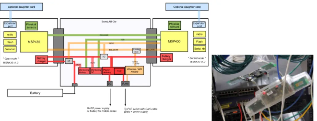
Fig. 5. (left) SensLAB gateway: The open node is on the left side and the control
node on the right side of the figure. In the middle, the GW itself links both nodes and allows to connect them to the main infrastructure backbone via an Ethernet link (PoE or Wifi). The GW also connects ADC/DAC ports of the control node to ADC/DAC ports of the open node in order to be able to ’replay’ sensing values and thus to provide reproducible environment. (right) Two SensLAB nodes connected to the backbone via PoE switch. One SensLAB node is protected by a specific box designed on purpose.
Fig. 6. Software SensLAB architecture and technological choices.
5 SensLAB Software Architecture
The SensLAB software architecture is replicated over the four testbed sites, and it is divided in several parts:
10
All designs are released under a Creative Commons License
11
Two version are developed: Version 1.3b presents an open 868MHz radio interface while version 1.4 has an IEEE 802.15.4 radio interface at 2.4GHz.
1. Control node software: the firmware running on the control node, in charge of powering up/down, resetting and doing measures on the open node activity (power consumption, radio activity/RSSI). It can set on its two DAC (digital to analog) pins any voltage between ground and power supply. Those pins are connected to the open node’s ADC (analog to digital converter), allowing the latter to react to these stimuli. All these actions can be executed asynchronously on the user’s request, or the measures command may be automatically and periodically executed. It is therefore available to the user to configure the quantities to poll and their period.
2. Gateway node software: the firmware running on the gateway manages the interface between the open and control nodes, and the SensLAB site server over IP communications. It forwards the command frames addressed to the control node, updates the open node’s firmware (BSL protocol), and forwards the open node’s serial link to the server (sink application); 3. Experiment handler software: The experiment handler software is the
server side interaction point with all the 256 site’s nodes. It can execute all the methods of the interfaces described above (firmware update, the energy consumption monitoring, polling). It also receives the data coming from the serial links of all the open nodes, encapsulated and relayed by the gateway nodes. chosen to use an OSGi framework because of its clear architectural or-ganization in bundles (Figure 7). When a user’s experiment ends, the testbed manager receives the information from the batch scheduler, commands the corresponding experiment manager to flash all the experiment’s nodes with a specific firmware to erase all memory from the nodes, and sets them in an idle state. Then the experiment manager object is unpublished from the RMI registry and deleted.
4. Batch scheduler software: Through a web form (or by uploading an xml file), the user configures his/her experiment and specifies wanted nodes (ei-ther mobile or fixed nodes, with a CC1100 or CC2420 radio chip, situated outdoor or indoor, located in Grenoble, Lille, Rennes or Strasbourg and the number of nodes), experiment’s duration and eventually a start date. Those last information are transmitted to the batch scheduler software, which is the server-side module allowing optimal experiments scheduling and resources allocation. It is also in charge of triggering start and stop of planned ex-periments, by invoking the experiment handler for nodes configuration and
resources release. This module is based on the use of OAR12
, which is a versatile resource manager (or batch scheduler) for large clusters.
5. User virtual machines: the complete Linux environment that is made available to each registered user allowing him/her to build sensor firmwares thanks to the complete set of tools installed, interact with the nodes of his/her running experiment (forcing reset, uploading a new firmware, ...) and running a dedicated application to handle the nodes’ serial link outputs (data logging, IP packets forwarding. . . ). A SensLAB specific command line client program is also available in each VM, providing to the user an interaction
12
means with the nodes of his/her running experiment. This client, an inter-active prompt, connects to the Experiment Handler software and performs firmware update, power supply modification and asynchronous measures on any of the experiment’s nodes.
6. Server system framework: the Linux system installed on each site server with the associated software suite needed to make the testbed functional (hypervisor, LDAP directory tree, SQL database, Apache Tomcat as a the servlet container, . . . )
Each of these parts is described in details below, to provide an in-depth understanding of all the functional parts that compose a SensLAB site: the kind of services, how they operate and how they cooperate altogether.
Fig. 7. Experiment Handler software structure. The experiment handler application
is a Java program that instantiates a ’testbed manager’ object and an OSGi container when started. The OSGi container embeds several bundles, responsible for all the interactions with the nodes: the Node Handler bundle sends command frames to the gateway and the control node; the Firmware Deployer bundle provides one service allowing parallel deployment of a firmware on several open nodes; the Sensor Controller bundle allows parallel sensor measurement such as power consumption, radio activity, or environmental measure; he Sink Forwarder bundle provides efficient data redirection between nodes and users’ VMs...
6 Experiment lifecycle on SensLAB
To illustrate the benefits of the SensLAB testbed in designing new algorithms, we give an overview of some applications that can be modeled and tuned through the SensLAB platform.
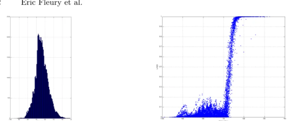
Fig. 8. RSSI distribution. Scatter plot of 1 − PER versus the RSSI for each link. The RSSI is the one measured for each received packet using the radio device FSK modulation. As expected we clearly have a threshold and 3 different zones. When the RSSI is greater than −65dBm , 1 − PER > 0.9 which means that every packet is received with a very high probability. On the other hand, when the RSSI is smaller than −70dBm, 1 − PER < 0.2 which implies very frequent packet losses. Between −70dBm and −65dBm we have a very sharp threshold: when the bit error rate is too high, the global packet is rejected by the modulation/physical layer.
6.1 Topology characterization
The first experiment consists of n = 255 receivers and 1 emitter. The emitter sends 32 bursts 128 packets every 10ms at a given transmitting power (typically -20dBm or 0dBm). All receivers are continuously listening the medium. We run 256 experiments sequentially: each node u ∈ {1 . . . 256} plays the role of the emitter once. The goal is to get the full adjacency matrix of the wireless links between every pair of nodes of a given SensLAB site. Each node is thus configure as a sink, using their own serial link to send continuously all packets received to the VM with the RSSI information for each packet. Such application stresses the feedback link since 255 nodes will use it. Figure 8 plots the distribution of the RSSI values of all packet received by all nodes. The rightmost plot on Figure 8 depicts the scatter plots of 1 − PER versus the RSSI for each link.
Finally, Figure 9 plots all the RSSI values for each link (i, j). We use the RSSI value to reorganized automatically the row and column by using a community detection algorithm [4]. The algorithm finds 4 clusters of nodes. Cluster 0 in the lower right corner is dense and well connected. On the opposite, the upper left cluster number 3 is bigger and not well connected and its size is twice bigger that the other ones but within this cluster a set of nodes (circle in green on the picture) is clearly well connected together and also with cluster number 2. Such an automatic clustering method helps us to define the basic clusters assignation that are configured within the reservation/schedule module. It also allows annotating the cluster by a relative quality and density.
Fig. 9. RSSI Matrix. Blue if a very low RSSI and red is a good RSSI value.
6.2 Animal tracking
We first focus on an animal tracking application [8]. Indeed, biologists need to track some animals to learn from their way of life (especially in natural parks). To do so, animals are instrumented with sensors. To geolocalize them, some fixed nodes called anchors are spread in the park and receive signals from mobile nodes as soon as they are in range. Anchor nodes register the mobile node identifier, the RSSI (Received Signal Strength Indicator) of the signal and the date. Then, these data needs to be routed to a sink node. This latter is connected to a computer gathering data and computing mobile node location based on these data. Note that geolocalization application has been simplified as possible since the main purpose here is to highlight SensLAB benefits. When anchors are deployed and powered on, the sink is initialized. It then starts to send BEACON and every anchor receiving this BEACON attaches itself to the sink. The sink becomes its parent. Then every attached anchor x forwards the BEACON. Every unattached anchor receiving a beacon from x chooses x as its parent. When every anchor has chosen a parent, the whole area is covered and mobile messages can be forwarded to the sink as follows. When an anchor receives a data message from another anchor or needs to send its own data, it forwards it to its parent. Step by step, the message eventually reaches the sink. The sink sends data through its serial link and the computer connected to it gathers the different messages and estimates mobile node positions.
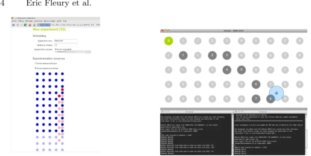
An Experimentation was conducted using the Lille’s SensLAB site where a grid of 5 × 10 nodes and 2 mobile nodes located on different train paths are reserved through the SensLab web portal (see fig. 10). Mobile nodes represent the animals while fixed nodes stand for anchor nodes. For the demo purpose, the VM is hosting an application which collects data from serial links, analyzes them to compute mobile node locations and provides a web server to visualize application status in real time (Fig. ??). Anchors, routes, messages and estimated mobile node positions can then be displayed in a web browser.
Fig. 10. The SensLAB web portal on the left. Demo visualization interface showing routes, messages transmission and mobile nodes location in the upper window, and messages printing on serial links for sink and mobile nodes on lower windows.
6.3 Illustrating the high radio channel randomness
A WSN is by nature random: radio propagation is rarely entirely predictive and owns a part of randomness, most MAC layers use a CSMA-CA approach [13], based on pseudo-random decisions in order to limit the channel contention, rout-ing decisions can be probabilistic to balance the load in the network [1], local-ization techniques may take benefit from probabilistic estimations [10], etc.
We proposed to exhibit visually this randomness, and to demonstrate that a testbed with the same inputs can lead to different resulting actions. We pro-pose an analogy with the casinos, and more specifically with the roulette. Users provide inputs to the experiment, and a pseudo-random result will be provided when it terminates.
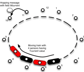
The demonstration integrates a roulette table: the testbed itself, constituted by all the static sensor nodes. To each sensor is assigned a number. The train represents the mobile part of the roulette table, capturing the ball when the experiment terminates. Finally, the ball is virtually represented by a message, acting as a token, jumping from one sensor (number) to another. The testbed takes into account several sources of randomness. Obviously, the radio prop-agation is not controlled: the multipath, shadowing, etc. will greatly affect the signal propagation. In the same way, we implemented a CSMA-CA opportunistic MAC layer, introducing some randomness. Finally, the ball acts as a token and is forwarded probabilistically: we implemented a geographic routing protocol, relaying the ball to the most accurate next hop. When the solution terminates (the ball reached its destination), geolocation solution with multilateration is used, associating the stopped ball with one number (the closest sensor). All these protocols constitute an independent challenge, and this experimentation aims at highlighting their interactions.
!"##$%&'()**+&) ,$-.'/)01'!"#$$%&' 2"3$%&'-4+$%',$-.' 5'*)%*"4*'.+3$%&' 6"#$$%&'()*+#% 7 8 9 5 : ; < = > 7? 77 78
Fig. 11. TTLis decremented while Age increases. A mobile node verifying T T L = Age
acknowledges the hopping message, defining the winning color. It then starts regular hello message transmissions and stops the train. Its position is evaluated based on a geolocation process. The closest static sensor indicates the winning number.
7 Conclusion
The architecture concepts, the hardware design, the software implementation of SensLAB, a large scale distributed open access sensor network testbed were presented. We have also sketch experiments in order to illustrate the possibilities of the testbed (non intrusive power consumption monitoring, self deployment, multi sink configuration). The testbed is deployed and under beta test in order to be totally open early 2011. Experiments using the whole testbed with inter
site interconnection are designed. More precisely, 6lowpan13
and ROLL14
exper-iments are scheduled. Research team, studying Networks Control Systems are also developing experiments in order to control several sites.
Several research works remain. One direction concerns the study of the fed-eration of research platforms, and more precisely with OneLab and PlanetLab. A federation called dF-LAB, will offer a higher dimension in the spectrum of ap-plications that the research community will design, test, deploy, and tune. But even more important, SensLAB will strongly benefit from the monitoring tools and supervising infrastructure developed and used in OneLab. Other extensions concern the use of hybrid simulation within SensLAB. The last extension is the development of actuator nodes, plugged directly on SensLAB nodes.
13
IPv6 over LoW Power wireless Area Networks
14
References
1. C. L. Barrett, S. J. Eidenbenz, L. Kroc, M. Marathe, and J. P. Smith. Parametric probabilistic sensor network routing. In WSNA. ACM, 2003.
2. T. Baumgartner, I. Chatzigiannakis, S. Fekete, C. Koninis, A. Kr¨oller, and
A. Pyrgelis. Wiselib: A generic algorithm library for heterogeneous sensor net-works. In EWSN 2010. LNCS 5970, 2010.
3. E. Ben Hamida, G. Chelius, and J.-M. Gorce. Impact of the physical layer mod-eling on the accuracy and scalability of wireless network simulation. Simulation, 85(9):574–588, 2009.
4. V. D. Blondel, J.-L. Guillaume, R. Lambiotte, and E. Lefebvre. Fast unfolding of communities in large networks. J.STAT.MECH., page P10008, 2008.
5. G. Chelius, A. Fraboulet, and E. Fleury. Worldsens: development and prototyping tools for application specific wireless sensors networks. In ACM, editor, Interna-tional Conference on Information Processing in Sensor Networks (IPSN), 2007.
6. V. Handziski, A. K¨opke, A. Willig, and A. Wolisz. Twist: A scalable and
reconfig-urable testbed for wireless indoor experiments with sensor networks. In RealMAN 2006, May 2006.
7. S. Kurkowski, T. Camp, and M. Colagrosso. Manet simulation studies: the incred-ibles. SIGMOBILE Mob. Comput. Commun. Rev., 9(4):50–61, 2005.
8. N. Mitton, T. Razafindralambo, and D. Simplot-Ryl. Theoretical Aspects of Dis-tributed Computing in Sensor Networks, chapter Position-Based Routing in Wire-less Ad Hoc and Sensor Networks. Springer, 2010. To appear.
9. K. Pawlikowski and J. L. R. Jeong. On credibility of simulation studies of telecom-munication networks. IEEE Comtelecom-munications Magazine, pages 132–139, 2001. 10. R. Peng and M. L. Sichitiu. Probabilistic localization for outdoor wireless sensor
networks. SIGMOBILE Mob. Comput. Commun. Rev., 11(1):53–64, 2007. 11. L. Peterson, A. Bavier, M. Fiuczynski, and S. Muir. Experiences implementing
planetlab. In OSDI, 2006.
12. D. Raychaudhuri, M. Ott, and I. Secker. Orbit radio grid tested for evaluation of next-generation wireless network protocols. In TRIDENTCOM, 2005.
13. I. Rhee, A. Warrier, M. Aia, and J. Min. Z-mac: a hybrid mac for wireless sensor networks. In SenSys. ACM, 2005.
14. B. White, J. Lepreau, L. Stoller, R. Ricci, S. Guruprasad, M. Newbold, M. Hi-bler, C. Barb, and A. Joglekar. An integrated experimental environment for dis-tributed systems and networks. In OSDI’02, pages 255–270, Boston, MA, Dec. 2002. USENIX Association.