HAL Id: lirmm-01276797
https://hal-lirmm.ccsd.cnrs.fr/lirmm-01276797
Submitted on 9 May 2019
HAL is a multi-disciplinary open access
archive for the deposit and dissemination of
sci-entific research documents, whether they are
pub-lished or not. The documents may come from
teaching and research institutions in France or
abroad, or from public or private research centers.
L’archive ouverte pluridisciplinaire HAL, est
destinée au dépôt et à la diffusion de documents
scientifiques de niveau recherche, publiés ou non,
émanant des établissements d’enseignement et de
recherche français ou étrangers, des laboratoires
publics ou privés.
Opening Web Applications for Third Party
Development: a Service-Oriented Solution
Mohamed Lamine Kerdoudi, Chouki Tibermacine, Salah Sadou
To cite this version:
Mohamed Lamine Kerdoudi, Chouki Tibermacine, Salah Sadou. Opening Web Applications for Third
Party Development: a Service-Oriented Solution. Service Oriented Computing and Applications,
Springer, 2016, 10 (4), pp.437-463. �10.1007/s11761-016-0192-7�. �lirmm-01276797�
(will be inserted by the editor)
Opening Web Applications for Third Party Development:
a Service-Oriented Solution
Mohamed Lamine Kerdoudi · Chouki Tibermacine · Salah Sadou
the date of receipt and acceptance should be inserted later
Abstract Web applications are nowadays prevalent software systems in our every-day’s life. A lot of these applications have been developed for end-users only. Thus, they are not designed by considering future ex-tensions that would be developed by third parties. One possible and interesting solution for opening these ap-plications for such kind of extension development is to create and deploy Web services starting from these ap-plications. In this paper, we present a method and a tool for semi-automatically creating Web service implemen-tations from applications having Web interfaces. The proposed method generates operations that are pub-lished in Web services for each functionality provided by a Web application. In addition, it generates new op-erations starting from Web interfaces. Our approach goes further in the creation of services by generating executable orchestrations, as BPEL processes, starting from navigations in the Web interfaces of these appli-cations and by providing BPMN choreography speci-fications starting from the collaborations between the generated Web services. We implemented and exper-imented our solution in the migration of three real-world Web applications towards Web service-oriented systems.
Keywords Web Application, SOA, Web Service, Service Composition and Application Migration Mohamed Lamine Kerdoudi
Computer Science Department, University of Biskra, Algeria E-mail: [email protected]
Chouki Tibermacine
LIRMM, CNRS and Montpellier University, France E-mail: [email protected]
Salah Sadou
IRISA, University of South Brittany, France E-mail: [email protected]
1 Introduction
Web applications are software systems that are widely used since the early nineties and the emergence of the World Wide Web. They have gained a lot of popularity comparatively to Desktop applications, because of their ease of use, via Web browsers, whereas Desktop appli-cations need sometimes heavy installations. These ap-plications provide to their users Web interfaces through which they can submit data to server-side scripts and through which they can receive the processing results.
The majority of Web applications have been de-signed and deployed exclusively for end-users that are humans. They have not been considered as a possible basis for remote extensions by third parties. For doing so, third party developers have no other choice than manually programming HTTP requests and then pars-ing the HTML code returned by these Web applica-tions. This represents a cumbersome task for a devel-oper especially that in most cases the parsed HTML code is too long and verbose. In addition, HTTP re-quests need frequently a detailed customization and HTTP responses need careful handling (dealing with errors and redirections).
In this paper, we propose a method for creating Web services by analyzing the source code and the config-uration files of Web applications. Our method helps the Web application providers in opening their soft-ware product for the development of extensions, with-out having to write the necessary code for doing so from scratch. The proposed method generates opera-tions that are published in Web services for each func-tionality provided by a Web application (methods and functions in the server-side source code of the applica-tion). In addition, it generates new operations starting from Web UI interfaces. This makes it possible to
pro-vide parameterizable services starting from pages de-signed for human interactions.
Besides the generation of these individual Web vices, the proposed method creates composite Web ser-vices. It creates executable orchestrations of the gen-erated Web services starting from the navigations be-tween Web interfaces of the analyzed application. These orchestrations are generated as BPEL [27] processes. They implement a coarse-grained functionality pro-vided by the Web application, comparatively with the individual Web services that implement fine-grained functionality. In addition, the proposed method creates choreographies of the generated Web services starting from the collaborations between them. These chore-ographies are specified in BPMN [32]. They provide models of a high level of abstraction, which help third party developers in understanding the architecture of the henceforth Web-service application.
We implemented our method on a collection of Java Frameworks. Component-based Web applications built with Java EE and its frameworks like JSF are the in-put of our implementation and a set of Web services are provided as output. The choice of such technologies is motivated by the fact that they offer a structured or-ganization of the source code of Web applications. This made easy the parsing performed in our approach in order to generate Web services.
The potential beneficiaries of this work are: i) the organization which holds the rights on the Web appli-cation and whose developers would use the proposed method: migrating a Web application of this organiza-tion towards a service-oriented one enables the organi-zation to modernize its “patrimony” and to shift to a new paradigm (of service orientation); ii) third party developers: they will be able to develop new business processes, potentially with financial benefits, starting from the generated Web services. The development of this “ecosystem” (composed of third party developers) around the generated services should necessarily bring a return on investment for the organization holding the rights on the original Web application.
The remaining of the paper is organized as follows. Section 2 introduces an example which better illustrates the problem tackled by our work and which serves as a running example for illustrating our proposals through-out the paper. Section 3 introduces a formal description of the context of our work, which is composed of Web applications and Web service-oriented systems. In Sec-tion 4 we give an overview of the proposed approach and we describe in detail how to create individual Web services starting from the components of the applica-tion. Section 5 introduces how the generated individual Web services are assembled to build composite services.
In Section 6 we apply our method on three real-world Web applications, and we use some measures to show the effectiveness of the proposed solution. Before con-cluding and presenting some perspectives to this work, we describe the related work in Section 7.
2 Illustrative Example
Our example is an e-shopping Web application that offers to customers the opportunity to purchase elec-tronic devices. The seller offers also delivery capabilities to ensure the transportation of the purchased items. The shopping process begins when the customer en-ters keywords for searching products via a Web inter-face (HTML form) provided by the application. A set of items which are relevant to these keywords are pro-vided and distributed on HTML pages. The customer can choose one or a set of items among the returned ones. The selected items are saved in a virtual cart and the total price is then calculated and provided via a Web interface. Once the customer finishes the shop-ping (s)he is asked to sign in or to register for a new account. At the end, before proceeding to checkout the delivery schedule is prepared and provided via another Web interface.
2.1 Problem Statement
Let us suppose now that a third-party developer would like to implement an extension to this Web applica-tion. This extension concerns services for the purchased items (insurance against theft, breakage, fire, etc). This extension provides first to customers an interface for searching products that are for sale by the original ap-plication. The customer selects a set of desired products and chooses the quantity for each one. The extended version of the application includes all the steps from the original version. However, it gives the opportunity to choose an insurance service and then integrate its cost to the final amount.
So, there are some functionalities needed by this ex-tension that are already provided by the original appli-cation (eg. searching, payment and delivery schedule). Therefore, for implementing this extension it would be interesting for the third-party developer if (s)he can use functionalities which are provided by the original appli-cation instead of implementing them from scratch.
In order to implement this solution, the third-party developer should have access to the functionality pro-vided by the Web application differently than via its Web interfaces. Indeed, if (s)he uses only these Web in-terfaces, (s)he should send from her(his) programs the
necessary HTTP requests, with customized parameters, and should then parse the returned HTTP responses. This parsing involves an analysis of the responses in or-der to look for some specific parts which are of interest. In our example, the third-party developer should im-plement a program that sends an HTTP request to the server hosting the Web application, with for example the reference(s) of the product(s) (chosen by the cus-tomer). The parsing should identify the price of the pur-chased items, among other elements. As stated in the introduction, this task is time-consuming, cumbersome and error prone. In addition, the developer should know the exact type and structure of the HTTP requests and responses.
Moreover, unfortunately, there is no means to di-rectly publish some services of the application for third party development. Even if stubs can be generated and provided for client applications, these stubs are gen-erally language-dependent (only Java clients can use stubs generated for EJBs) and cannot be published, as they are, in libraries of services. Besides, the EJB 3.x specification introduced some annotations to enable de-velopers to publish some methods in a bean as services. However, this is possible only for individual methods and we cannot introduce annotations to create compo-sition of operations which we found in real-world busi-ness logic. In addition, we cannot use these annotations to expose Web interfaces as Web services. The same ob-servations can be made on Eclipse tools (WTP project), which allow to generate Web services starting from in-dividual methods in Java classes.
2.2 Potential Web Services
One of the best solutions for the previous problem is to enable the Web developer to create starting from the Web application a set of Web services suitable for re-mote extensions. In the presented example, the created Web services could be: a Searching Service for search-ing items, a Cart Service to manage a virtual shoppsearch-ing cart, an Account Service used to sign in or to register for a new account, a Delivery Service and a Payment Service.
The application extension scenario introduced pre-viously can easily be implemented by remotely invoking the Web service operations. The extension of the shop-ping Web application can even be built simply as a BPEL process by invoking the Searching Web service using the reference of the chosen product as input. The returned price is added to the insurance’s price.
The BPEL process makes the payment of the pur-chased products (without insurance) from the original Web application by invoking the generated Payment
Web service. After that, to pay the insurance costs, the BPEL process invokes an operation that is implemented by the third party developer. At the end of this process, it invokes the Delivery Service.
3 Web applications and Service oriented Systems
Before presenting the details of our approach and how Web service-oriented systems can be derived from Web applications, we define in this section the different con-cepts used in this work. Indeed, we introduce formal de-scriptions of what composes Web applications and Web service oriented systems. These formal descriptions pro-vide a better understanding of both kinds of software systems. In addition, this enables an accurate presenta-tion of the processing performed on Web applicapresenta-tions to generate Web service systems.
3.1 Web application Model
We adapt here the generic model of Briand et al. [?] to represent Web applications and their elements as a directed graph expressed using a set-theoretic notation. This graph is expressed as a pair (E, R), where E sym-bolizes a set of software entities found in a Web appli-cation, namely, client side artifacts and server side artifacts. R is a binary relation on E(R ⊆ E × E). It corresponds to the relationships between Web application elements, representing both structural and behavioral dependencies. Figure 1 gives an example of such a representation for an imaginary Web applica-tion.
Definition 1 Representation of a Web application A Web application is represented as a pair (E, R), where
– E = CSA ∪ SSA with:
– CSA is the set of all client side artifacts which are HTML Web pages (W P in Figure 1) and Client Scripts (CS in Figure 1).
– SSA is the set of all server side artifacts which are Server Scripts (SeS in Figure 1) and Server Classes (SC in Figure 1)
– R is the set of all common and possible relationships between artifacts of Web applications with:
– (CSA × SeS) corresponding to relationships between static Web pages and server side scripts (such as submit, build, redirect, clientScriptRequest, among other relation-ships in Figure 1)
SeS(ses3) W P(wp1) CS(cs1) W P(wp2) SeS(ses1) SC(sc1) SC(sc2) SC(sc3) SeS(ses2) submit use use redirect use build include clientScriptRequest clientScriptResponse
Fig. 1 Structure of a Web application
– (SeS × SC) corresponding to relationships be-tween server scripts and server classes (eg. (ses1
use sc1) in Figure 1)
– (SeS × SeS) corresponding to relationships be-tween server scripts (eg. redirect in Figure 1) – (SC × SC) corresponding to relationships be-tween server classes (eg. (sc1 use sc3) in
Fig-ure 1)
– (CSA × CSA) corresponding to relationships that exist between client side artifacts (eg. (wp1
include cs1) in Figure 1)
For instance, for the example given in Figure 1 we have: – CSA = { wp1, wp2, cs1}
– SSA = { ses1, ses2, ses3, sc1, sc2, sc3}
– R = {(wp1include cs1), (ses2 build wp2),...}
3.1.1 Representation of a Web Interface
A Web (user) interface (UI) may be formally defined as a sub-graph of the graph representing the Web applica-tion to which it belongs. Thus, a Web UI is defined by a pair (Ewui, Rwui) such as: Ewui= (CSAwui∪ SSAwui)
with (CSAwui ⊆ CSA) ∧ (SSAwui⊆ SSA) ∧ (Rwui ⊆
R)
A Web UI consists of server pages, client static pages and client built pages. The server pages are deployed on the Web server and could manipulate some server classes; client static pages have a static content which is composed of HTML tags; the content of client built pages is generated on the fly by the server pages after processing user’s requests.
3.1.2 Example of a Web Interface Sub-Graph
Considering our example of the e-shopping application. In the Cart Web UI the total price of all saved items in the user’s cart is calculated and presented to users via a Web interface.
W P(showCart.html)
W P(cartDetails.html)
SeS(totalP riceInCart.jsp)
SC(Item.java) SC(P roducts.java) submit use use build
Fig. 2 A sub-graph representing the Cart Web Interface
Figure 2 shows a sub-graph that represents the Cart Web UI1 where,
– W P = { showCart.html, cartDetails.html} – SeS = {totalP riceInCart.jsp}
– SC = { Item.java, P roducts.java }
– R={(totalP riceInCart.jsp use Item.java),... } In this sub-graph, the user can access the cart through the client page showCart.html. In order to calculate the total price of the products in the cart, the user can submit data (such as product references and quantities) to the server script located in the JSP page totalP riceInCart.jsp. As a result, the total price is dis-played to the user via the client page cartDetails.html. 3.1.3 Properties of server side artifacts
We define a set of structural and behavioral properties related to server side artifacts as follow:
– Request Parameters: are the data entered by users when manipulating a Web interface and which are processed by a server side script.
1 This sub-graph is used as an illustrative example
For each element ses ∈ SeS,
RP (ses) is the set of request parameters which are processed by the server script ses.
– Environment Objects: Each server side script could manipulate a set of environment objects such as session variables, cookies and business objects in order to store and share user’s data.
For each element ses ∈ SeS,
EO(ses) is the set of environment objects which are manipulated by the server script ses.
– Produced Contents: For each element ses ∈ SeS, P C(ses) is the set of produced contents by a server side script as a result of processing user’s requests. – Statements of Server Scripts: For each ses ∈
SeS, Stats(ses) is the set of all statements declared in ses.
– Methods of Server Classes: For each sc ∈ SC, M (sc) is the set of all methods declared in a server class sc.
– Method parameters: Each server method has a set of parameters, where
For each method m ∈ M (sc),
IP ar(m) is the set of input parameters of m and OP ar(m) is the set of output parameters of m. – Navigation Condition: N C(wp) represents the
as-sociated navigation condition to a Web page wp. It states that the user action navigates dynami-cally from the Web page wp to another page. In most web applications, navigation is not static. The page flow does not just depend on which button the user clicks, but also on the input value that (s)he introduces. For example, submitting a login page may have two outcomes: success or failure. The out-come depends on a computation (result of reference method invocation), namely, whether the username and password are valid.
The presented model and the set of definitions are used later throughout the paper.
3.2 Web Service Oriented System Model
Perepletchikov et al. [?] extended the generic model proposed by Briand et al. [?] and proposed a model covering structural and behavioral properties of the de-sign artifacts in service-oriented systems. We adapt this model for representing the generated Web Service ori-ented application as a graph. In this graph, the WSDL files are used as service interfaces and Object-oriented (OO) classes are implementations for the primitive Web services. BPEL processes are used as implementations of the generated Web service orchestrations.
Fig. 3 shows an example of a graph representing the software entities of an imaginary Web service-oriented application.
Definition 2 Representation of a Web Service-oriented System
A Web service-oriented system is represented as a pair (Esos, Rsos), where
– Esos= SI ∪ BP ∪ C ;
– SI is a set of all service (WSDL) interfaces; – BP is a set (possibly empty) of all BPEL processes
that implement the WSDL service interfaces of the Web service orchestrations;
– C is a set of all OO classes that implement WSDL service interfaces of primitive Web services ; – Rsos is the set of all common and possible
relation-ships between the sets SI, BP and C. So, Rsos =
IIR ∪ ISR ∪ WSR with,
– IIR (Interface Implementation Relationship) represents relationships between service interface and service implementation elements. A Service interface could be implemented using OO classes and/or business processes.
– ISR (Internal Service Relationship) represents relationships between classes. Two classes in a given service could have a dependency relation-ship when an object of the first class invokes the methods (on objects) of the second class. – WSR (Web Service Request Relationship)
repre-sents relationships between a class (or a Busi-ness process) of a particular service and a service interface of another service. A class (or BPEL process) can invoke the operations defined in the service interface of another service.
For instance, for the graph given in Figure 3 we have:
– SI = {si1, si2}
– C = {c1, c2, c3, c4, c5, c6}
– BP = {bpel1}
– R= {(si1IIR c1), (c1 ISR c2), (c3 WSR si2),...}
A Web service may be formally defined as a sub-graph of the sub-graph representing the Web service-oriented system to which it belongs. Thus, a Web ser-vice is defined by a pair (Es, Rs): Es= (SIs∪BPs∪Cs)
where (SIs∈ SI) ∧ (BPs⊆ BP ) ∧ (Cs⊆ C) ∧ (Rs⊆ R)
with,
– A Web service has only a single service interface SIs
– Each Web service exposes a set of operations, where – For each element e ∈ SI ∪ BP ∪ C,
SI(si1) Service(ser1) C(c1) C(c2) C(c3) C(c4) IIR IIR ISR ISR ISR SI(si2) Service(ser2) C(c5) C(c6) BP(bpel1) IIR IIR ISR W SR
Fig. 3 Structure of a Web Service-oriented System
– For each operation o ∈ O(e),
IP aram(o) is the set of input parameters of o; OP aram(o) is the set of output parameters of o. – For each operation o ∈ O(e) ∧ e ∈ C,
Code(o) is the set of all statements of o.
3.2.1 Example of Web service-oriented system graph Returning to the Cart Web UI presented previously (Section 3.1.2), Fig. 4 shows a graph SOSsos1 =
(Esos1, Rsos1) that represents the Web services which
could be generated starting from this Web UI. – SI = {wsdlCart, wsdlP roducts}
– C = {CartService, Item, P roductsService} – BP = {}
– R = {(wsdlCart IIR CartService), (CartService WSR wsdlP roducts),...}
In this sub-graph, Service(ser1) represents the generated Web service starting from server scripts in the Cart Web UI and Service(ser2) represents the generated Web service starting from the server class P roducts.java. The W SR relationship repre-sents an invocation to an operation published in wsdlP roducts interface from the source code of the class C(CartService). This relationship represents an invocation from a server script in the Cart Web UI to a method (this method is exposed later as a Web service operation) located in the P roducts.java class.
SI(wsdlCart) Service(ser1) C(CartService) C(Item) IIR ISR SI(wsdlP roducts) Service(ser2) C(P roductsService) IIR W SR
Fig. 4 A sub-graph that represents the generated Web ser-vices from the Cart Web Interface (SOS1)
4 Proposed Approach
This section covers the proposed solution for mi-grating Web applications toward Web service-oriented systems. First, we give an overview of the proposed ap-proach. Then, we present in detail each step in the pro-cess.
4.1 General Overview
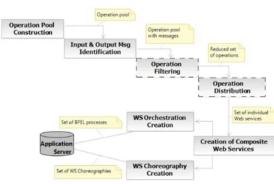
The creation of Web services from Web applications is a semi-automatic multi-step process. This is illustrated in Fig. 5. The dashed boxes in the process represent steps where the developer is involved. This process begins by receiving from the developer as input the source code and the configuration files of the Web application to be analyzed. A set of primitive and composite Web services are provided as output.
To present the details of our approach accurately, we use the previous formal definitions to represent the input Web application as a pair (E, R) and the de-sired Web service oriented solution as another pair (Esos, Rsos). Moreover, we show how to generate the
Web service oriented application as a mapping from a Web application graph to a Web service-oriented sys-tem graph.
The algorithm 1 introduces a sequence of the main functions and procedures used to apply this mapping. In this algorithm we follow the same logic of steps in Fig. 5. First, each element in a Web application is statically parsed to identify the potential set of oper-ations with their input and output messages. The op-erations can be identified starting from existing meth-ods in server classes (see Line 3) and from the server
Fig. 5 The Proposed Process
scripts that provide functionalities via Web UIs (see Line 5). Then, all operations that must not be pub-lished in Web services are eliminated. This needs the contribution of the developer. (S)he should manually remove these unwanted operations. Besides, we provide to the developer a way for specifying constraints so that the operations that are recurrently unwanted can be automatically removed (see Line 9). After that, the re-maining operations are grouped in Web services (see Line 10) and represented as sub-graphs of the output graph. The dependencies between Web services are then identified and represented using the W SR relationships (see Line 11). At the end, a set of Web service orchestra-tions are created (see Line 12) and added as additional sub-graphs of the output graph. Hereinafter we detail each function in the process.
Algorithm 1 From a Web application model to a Web service-oriented system model
Input: Web application modelW A= (E, R)
Output: Web service-oriented system model SOS = (Esos, Rsos)
1: for all e ∈ E do
2: if e ∈ SC then
3: s=identif yExistingOperations(e) 4: else if e ∈ SeS then
5: s=identif yOperationsF romW ebInterf aces(e) 6: end if
7: add (s, SOS) 8: end for
9: f ilterU nwantedOperations(SOS, oclConstraints) 10: distributeOperations(SOS)
11: createChoreographies(SOS) 12: createBP ELP rocesses(SOS) 13: return SOS
4.2 Operation Pool Construction
A pool of operations is constructed by parsing the Web application’s contents. Two kinds of operations are cre-ated.
4.2.1 Identification of Existing Operations
These operations are generated starting from the ex-isting methods and functions in the back-end compo-nents of the Web application. To do so, we statically parse different elements (e.g. classes or server scripts) of the Web components forming the transformed appli-cation. All methods in classes and functions in scripts are prepared to be considered as potential operations in Web services. For instance, in the example presented in section 3.1.2 the public methods that are declared in the P roducts.java class are transformed into new operations. Algorithm 2 shows how to create a service containing operations that are generated starting from existing public methods in a server class.
Algorithm 2 Identify Existing Operations
1: function identifyExistingOperations(serverClass:SC) 2: s= create Service: s=(SIs, BPs, Cs, Rs) .s is
subgraph of a service
3: wsdl=create ServiceInterf ace:wsdl ∈ SIs
4: c=create Class:c ∈ Cs
5: r=create IIR:r= (wsdl IIR c)∧ r ∈ Rs
6: for all m ∈ M(serverClass)do
7: if isP ublic(m)then
8: createN ewOperation(s, c, m, wsdl)
9: end if
10: end for
11: return s
Therefore, the service interface and its implementa-tion class are created here (see Lines 3 to 5 in Algo-rithm 2).
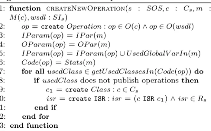
Algorithm 3 gives the details of how to create opera-tions. Each access to global variables or attributes from the source code of the identified methods and functions is transformed into additional parameters (see Line 5 in Algorithm 3). This makes these operations stateless. Moreover, each server class and all their dependent in-ternal classes (which does not publish operations) are grouped together to form a Web service (see Lines 7 to 12 in Algorithm 3).
Algorithm 3 Create New Operation
1: function createNewOperation(s : SOS, c : Cs, m : M(c), wsdl:SIs)
2: op=create Operation:op ∈ O(c)∧ op ∈ O(wsdl) 3: IP aram(op) =IP ar(m)
4: OP aram(op) =OP ar(m)
5: IP aram(op) =IP aram(op)∪ U sedGlobalV arIn(m) 6: Code(op) =Stats(m)
7: for all usedClass ∈ getU sedClassesIn(Code(op))do
8: if usedClassdoes not publish operationsthen
9: c1 =create Class:c ∈ Cs
10: isr=create ISR:isr= (c ISR c1)∧ isr ∈ Rs
11: end if
12: end for
13: end function
4.2.2 Creation of New Operations from Web Interfaces The main entities of a Web application are the Web user interfaces that consist of server’s pages and client’s pages. Through client pages, the end-users can submit data to server-side scripts and through which they can receive the processing results.
The public functionalities which are accessible via Web interfaces from end-users are transformed into new operations. These operations have as parameters the data entered by users when manipulating the Web in-terface (data entered in forms, for example), and have as output the results returned by the scripts processing the data entered by the users. In other words, the code present in programs executed at the server-side (JSP or PHP scripts, for example) is grouped within new op-erations and formatted to be executed as stand-alone code. For example, all the code present in scriptlets of a JSP page which implements a provided function-ality to users is grouped and formatted within a sin-gle operation. For instance, in the Web interface pre-sented in section 3.1.2, the code present in scriptlets of totalP riceInCart.jsp server page is formatted within a new operation exposed by the wsdlCart interface in
Fig. 4. More details about this transformation is given in the next section.
Therefore, the Web interfaces that use a secure pro-tocol such as TSL(SSL) [?] to protect the exchanged messages content or to authenticate the client by using a clients public key certificate are migrated toward a se-cure Web service that uses the same protocol. Indeed, the source code that implement the TSL(SSL) protocol in the Web interface is formatted to be a secure Web service. In this way, our approach will not weaken the migrated Web application security level.
Besides, a Web interface may include a Frameset composed of one or more frames, and in each frame, there is a content which could be dynamically loaded from elsewhere (Web intefaces, texts, images, etc.). For example, the <iframe src="URL"> tags are used to em-bed another content (HTML, JSP, PHP...) within a given HTML, JSP or PHP document. For such tags, the inline frame (document) sometimes corresponds to a Web interface, which has been transformed into a Web service. In this case, an invocation to this Web service is added in the source code of the operation cre-ated starting from the currently analyzed Web inter-face. This invocation allows to retrieve some data from the server.
Algorithm 4 shows how to create a Web service sub-graph starting from a Web interface sub-sub-graph. First, the service interface and its implementation class are created (see Lines 3 to 5). After that, a new operation is created from the Web interface (see Lines 6 to 9 ). This operation and its internal dependent classes are grouped within a Web service (see Lines 10 to 15). In other words, for each dependent class we create a node of type Cs. This node is connected to the class that
implements the service with an ISR relationship. For example, in Fig. 4 the C(Item.java) class is an internal class used by the C(CartService) class. Additional op-erations are also generated from the existing methods in the server page (see Lines 16 to 20).
4.3 Input and Output Message Generation
Based on the result of the first step, the input and out-put messages related to each operation in Web services are identified and generated starting from the parsed elements in the Web application: i) For operations in classes and other structured code elements, the param-eters and the returned values are formatted as (respec-tively, input and output) SOAP messages (see Lines 3 and 4 in Algorithm 3); ii) The saved data in HTTP re-quests and HTTP responses are parsed to extract new input and output messages (see Lines 7 and 8 in the
Algorithm 4); iii) The used environment objects (ses-sion variables, cookies and business objects) by the Web interface are considered as input and output messages (see Lines 7 and 8 in Algorithm 4).
Algorithm 4 Identify Operations From Web Interfaces 1: function
identifyOperationsFromWebInter-faces(serverClass:SeS)
2: s= create Service: s=(SIs, BPs, Cs, Rs) .s is
subgraph of a service
3: wsdl=create ServiceInterf ace:wsdl ∈ SIs
4: c=create Class:c ∈ Cs
5: r=create IIR:r= (wsdl IIR c)∧ r ∈ Rs
6: op=create Operation:op ∈ O(c)∧ op ∈ O(wsdl) 7: IP aram(op) =RP(ses)∪ EO(ses)
8: OP aram(op) =P C(ses)∪ EO(ses) 9: Code(op) =F ilter(Stats(m))
10: for all usedClass ∈ getU sedClassesIn(Code(op))do
11: if usedClassdoes not publish operationsthen
12: c1 =create Class:c ∈ Cs
13: isr=create ISR:isr= (c ISR c1)∧ isr ∈ Rs
14: end if
15: end for
16: for all meth ∈ declaredM ethodIn(ses)do
17: if isP ublic(m)then
18: createN ewOperation(s, c, meth, wsdl)
19: end if
20: end for
21: return s
22: end function
4.3.1 Dealing with HTTP requests and HTTP responses
The code present in the server programs (e.g. server pages like JSP or PHP pages) is parsed to extract the input values received in the HTTP requests (by identifying the statements getting values from HTTP requests). Their types are deduced from the parsed code by analyzing type casts and other conversion statements. This is directly possible in statically typed scripting languages like JSP and C]. For dynamically typed ones (like PHP or Python), we use external tools for type inference. In addition, the shared objects (such as JavaBeans instances), which are used across multi-ple Web interfaces, are considered as additional input parameters for the generated operation. In this way the saved data in these objects can be passed from an op-eration to another in order to compose them.
Furthermore, the contents produced by the server programs, which are viewed at the client side (this con-tent is produced using statements such as: JSP expres-sions or out.println(...) for JSP and PHP’s echo() or print() function calls), are considered as output values. The types of these values are extracted from the code and defined in the generated SOAP messages.
The arguments of the out.println(...) or echo(...) methods can be variables, method invocations or ex-pressions. For variables, we get their type from the parsed code. In the case of method invocations, the type of the generated output message corresponds to the returned type of the invoked method. The expres-sions can be a concatenation of texts and values of vari-ables and/or method invocations. In this case, the val-ues from method invocations and the variable accesses are extracted to be added as output values of the gen-erated operation. The text is added as another output. Let us consider the Cart Web UI of our ex-ample presented in Section 3.1.2. This interface al-lows users to calculate the total price of her/his items. Listing 1 shows an excerpt of the code present in the totalP riceInCart.jsp server script. Two input messages are identified starting from the request.getParameterValues(...) statements (see Lines 8 and 9). They correspond to the references of the selected items to be purchased and the quantities wanted by the user for each selected item. Another in-put message is extracted from the used JavaBean ob-ject prods. For the sub-graph created for this Web interface (see Fig. 2), we represent these values as: RP ={ref erences, quantities} and EO= {prods}.
1 <jsp:useBean class="shop.prod.Products" id="prods" scope ="page"/> 2 <%! 3 String[] references; 4 String[] quantities; 5 double totalPrice = 0; 6 %> 7 <%
8 references = request.getParameterValues("references");
9 quantities = request.getParameterValues("quantities");
10 if(references != null){
11 for(int i = 0; i < references.length; i++){ 12 Item item = prods.getItemByReference(references[i]); 13 double unitPrice = item.getUnitPrice();
14 int quantity = Integer.parseInt(quantities[i]);
15 totalPrice = totalPrice + calculateTPrice( unitPrice, quantity);
16 }
17 }
18 %>
19 <%= totalPrice %>
Listing 1 An excerpt of the code present in the Cart Web interface
The type of the references input is an array of Strings. From the conversion statement (see Line 14) we have deduced that the type of quantities is an array of Integers.
Finally, we have deleted from the source code of the generated operation: the conversion, the cast and the request.getParameterValues(...) state-ments (Lines 8, 9 and 14 in Listing 1). The returned value of the generated operation is the result saved in the variable totalPrice and bound to the Web inter-face using a JSP expression (Line 19). This is used to create an output SOAP message of type Double (in our sub-graph, we have P C = {totalP rice}).
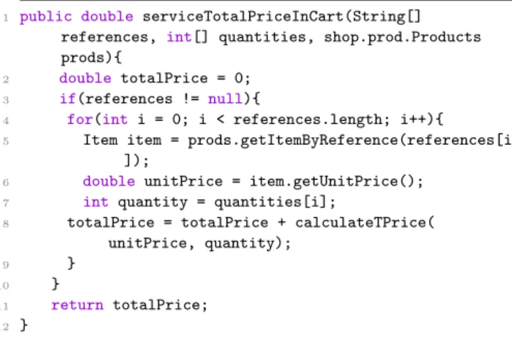
Applying the two first steps and making the neces-sary modifications for the previous source code, a new operation is created (see Listing 2). For that, four input parameters and a returned value are identified.
1 public double serviceTotalPriceInCart(String[] references, int[] quantities, shop.prod.Products prods){
2 double totalPrice = 0;
3 if(references != null){
4 for(int i = 0; i < references.length; i++){ 5 Item item = prods.getItemByReference(references[i
]);
6 double unitPrice = item.getUnitPrice();
7 int quantity = quantities[i];
8 totalPrice = totalPrice + calculateTPrice( unitPrice, quantity);
9 }
10 }
11 return totalPrice;
12 }
Listing 2 An excerpt of the generated operation from the
CartWeb interface
Fig. 4 shows the subgraph that represents the gen-erated Web service from the Cart Web interface and the server class Products, where, the following values represent these services.
– O(CartService) ={totalP riceInCart, calculateT P rice,...}
– IP aram(totalP riceInCart)= {ref erences, quantities, prods }
– OP aram(totalP riceInCart) = { totalP rice} – IP aram(calculateT P rice)={unitP rice, quantity} – OP aram(calculateT P rice) = {T P rice}
– O(P roducts) = {getItemByRef erence, getItemDetails,...}
4.3.2 Handling Session Objects
Most of Web applications manage session variables in order to store and share the user’s data when (s)he nav-igates from a Web interface to another one. To avoid losing this data and make possible using them in the composition of the generated Web services from the Web interfaces, we consider these values as additional input and output messages.
The user’s data that is stored in these session ob-jects could be used as constraints for accessing other Web interfaces when the user navigates in the appli-cation. Therefore, the output messages generated from the first Web interface are considered as the input to the generated services from the navigated Web interfaces. This ensures that these services are not freely accessible (preserve security). In order to generate these messages, we parse the code present in operations that use session variables.
In our illustrative example, the addItem Web in-terface is used to add a new item into a virtual cart. Listing 3 shows an example of using session variables to store information about the cart. The quantity and the reference are identified and considered as input messages. They are identified after the parsing of the request.getParameter(...) statements (as ex-plained in the previous section). Now, statements such as session.getAttribute(...) (see Lines 2 and 11) return the objects bound to the name ’currentCart’ specified in this session. So, this object is transformed into an additional input. The session objects can be up-dated in the source code (see Line 18). For this reason, they are also considered as output messages of the gen-erated operation. After analyzing the cast statements in Lines 2 and 11 we have deduced that the concrete type of the ’currentCart’ message is Cart.
1 <%
2 Cart currentCart =(Cart) session.getAttribute(" currentCart");
3 // return the object bound with the name ’currentCart’ in this session, or null if no object is bound under this name
4 Cart newCart = null;
5 if (currentCart == null){
6 //binds a new object ’newCart’ to this session using the name "currentCart"
7 newCart = new Cart();
8 session.setAttribute("currentCart",newCart);
9 }
10 else {
11 newCart = (Cart) session.getAttribute("
currentCart");
12 }
13 String StrQuantity = request.getParameter("quantity");
14 int quantity = Integer.parseInt(StrQuantity);
15 if (quantity > 0){
16 String reference = request.getParameter(" reference");
17 // update the Cart and the object bound the this session
18 newCart.addItem(reference,quantity);
19 }
20 out.println(newCart.getTotalPrice())
21 %>
Listing 3 An excerpt of a server script present in theaddItem
In addition, the parsing of statements that are used to bind an object to a session, such as: session.setAttribute(...,...), generates addi-tional output messages. For example, from the Line 8 we create an output message named ’currentCart’. At the end, an additional output message correspond-ing to the calculated price is generated from the parscorrespond-ing of the statement out.println(...) (see Line 20). The type of this output corresponds to the returned type of getTotalPrice method that is Double.
Listing 4 shows an excerpt of the newly created operation. It allows to add a new item in the vir-tual cart. This operation receives three input messages (reference, quantity and currentCart) and returns a composed message that contains the new total price and the updated virtual cart. However, the statements that use session variables are removed from the code of this operation.
1 public AddItemOutput serviceAddItem(String reference,
int quantity , Cart currentCart ){
2 Cart newCart = null;
3 if (currentCart == null){
4 newCart = new Cart();
5 currentCart = newCart; 6 } 7 else { 8 newCart = currentCart; 9 } 10 if (quantity >0){ 11 newCart.addItem(reference,quantity); 12 }
13 return (new AddItemOutput(newCart.getTotalPrice(), currentCart));
14 }
Listing 4 An excerpt of the generated operation from
addItemWeb interface
4.3.3 Dealing with Cookies
Actually, the server can maintain information about user sessions in many ways such as using cookies. In our approach, the used set of cookies is consid-ered as input and output messages. The statements which are used to access and to modify the saved cookies (e.g. in a JSP page, request.getCookies() and response.addCookie(...)) are identified and re-placed in the body of the new generated operation with equivalent statements accessing these new messages. Listing 5 shows an example of using cookies to save information about user authentication in the signIn Web interface.
The parsing of this code has identified one in-put message which is defined starting from the request.getCookies() statement (see Line 2). This
input value corresponds to a set of cookies that are used in the generated operation’s code. This set of cookies is returned as output message of this operation in order to be used as input of another operation generated from another Web interface that uses these cookies. In this way the composition of these two operations would be easier.
1 <%
2 Cookie[] cookies = request.getCookies();
3 String email = "", password ="";
4 if( cookies != null ){
5 for(Cookie cookie : cookies){
6 if (cookie.getName().equals("email")){ 7 email = cookie.getValue(); 8 } 9 if(cookie.getName().equals("password")){ 10 password = cookie.getValue(); 11 } 12 }
13 AccountManager userId= new AccountManager();
14 if(userId.signIn(email,password)){
15 // ....
16 }
17 }
18 %>
Listing 5 An excerpt of code showing the using of cookies in thesignInWeb interface
The generated operation has a body with the same code as the script shown above, except the statement at Line 2. This Line is replaced with a statement which is used for extracting the cookies from an object of type Collection (obj.getCookies()) received as an ar-gument. In addition, a “return” statement is added at the end of the operation’s body, which returns this object (retun obj;).
4.4 Operation Filtering
In this step, the identified pool of operations is filtered by eliminating the operations which are not suitable to be published in Web services. For example, the modern Web applications use Public and Private APIs. Thus, by this filtering task, we allow developers to eliminate all operations that are identified from Private APIs. The filtering cannot be fully automated and it needs the developer involvement. The developer is asked to choose among the selected operations those that are not interesting for a publication. A set of filtering ex-pressions are made available to be used and enriched by the developer. Some kinds of operations are recurrent in most of applications. Therefore, the specified expres-sions could be reused by another developer in order to filter operations which are generated starting from other Web applications. The developer will not have to
Fig. 6 The Operation Meta-model
specify them from scratch. These expressions are con-straints that are checked on an Ecore [13] instance of a meta-model representing operations. These instances of the meta-model are automatically built by analyzing the operations’ code. Constraints are Boolean expres-sions which are specified using OCL (Object Constraint Language [30]). OCL has been chosen because of its simplicity [6] and the existence of a good tool support (OCL Toolkit [10], Eclipse MDT/OCL [14], ...). The specified constraints navigate in the meta-model, which is illustrated in Figure 6. This meta-model is an excerpt of the UML meta-model (related to operations) [33] ex-tended with some basic constructs.
The main meta-class in Figure 6 is Operation, which represents an identified operation from the code. The Operation class is associated to a Type meta-class which represents the returned type of the opera-tion. In addition, this operation could have a body and a set of parameters.
All constraints have as a context an instance of the Operation meta-class. An example of a constraint is given below:
context Operation inv :
not ((self.returnedType.name= ’void’) and (self.name.substring(1,3) = ’set’) and (self.ownedParameter->size() = 1) and self.body.statement->exists( kind =
’AssignmentStatement’ and isFieldAccess = ’true’)
In this example, all operations that represent field accessors (for example, setter methods) are eliminated.
4.5 Operation Distribution in Services
The extracted operations are distributed on multi-ple Web services based on the following criteria:
4.5.1 Grouping Criterion
We group operations based on the cohesion and cou-pling criteria. We argue that an optimal granularity is the key to a well-designed service. Service granularity generally refers to the performance and size of a ser-vice [?]. The data granularity is one of serser-vice granu-larity types [?]. It reflects the amount of data that is exchanged with a service. A good grouping of the iden-tified operations in Web services has a positive impact on the data granularity. In our approach, the highly coupled and cohesive operations are grouped together in a single Web service. And, the low coupled opera-tions are distributed on multiple services. This strat-egy of grouping reflects a low amount of data which is exchanged and reduces the communication overhead. Hence from the service quality viewpoint, we increase the performance and the maintainability of the gener-ated services.
The cohesion of a service is assessed based the de-gree of the strength of functional relatedness of oper-ations within a service. We measure the cohesion of a service by analyzing the static invocations between op-erations within that service. Several cohesion metrics have been proposed in the literature in order to mea-sure the cohesion of a class in an object-oriented sys-tem [7]. We believe that one of these metrics can be used to evaluate the cohesiveness of the generated Web services. The LCOM (Lack of Cohesion in Methods), T CC (Tight Class Cohesion) and LCC (Loose Class Cohesion) are one of the most used metrics to mea-sure cohesion between public methods in a class. The problem with LCOM metric is that such metric only helps in identifying the absence of cohesion rather than its presence [?]. On the contrary, we need in our work to measure the presence of cohesion in Web services. For this reason we use the T CC and LCC metrics to measure service cohesion. To do so, we start with a flat organization of operations (all operations are dis-tributed in one Web service). Then, we calculate T CC and LCC to check the cohesiveness of this Web service. If the service is not cohesive, we split it into set of low coupling services and we check again the cohesiveness of each one of them. We repeat the measurement until the produced services are “quite cohesive”.
To measure the T CC, we consider a Web service with N operations. NP is the maximum number of op-eration’s pairs:N P = [N ∗ (N − 1)]/2. The N DC is the number of direct connections between operations. Then T CC is defined as the relative number of directly connected operations: T CC = N DC/N P .
To measure LCC, we consider NIC is the number of indirect connections between operations (when two
operations are connected via other operations). LCC is defined as the relative number of directly or indirectly connected operations: LCC = N DC + N IC/N P .
According to [3], a class (a service in our case) is con-sidered non-cohesive when T CC < 0.5 and LCC < 0.5. If LCC = 0.8 the class is considered ”strongly cohe-sive”. If T CC = LCC = 1 then the class is maximally cohesive, which means all methods are connected. In our approach, we experimentally tested these metrics and we found out that with T CC > 0.5 or LCC > 0.5 the obtained Web services are “quite cohesive”.
Algorithm 5 shows how the grouping is performed. First, each group of operations is represented with a graph which is expressed as a pair (OP, CON ), where OP symbolizes a set of operations. CON is a binary relation on CON (⊆ OP × OP ). It corresponds to the direct and indirect connections between operations.
The input of this algorithm is a group that contains all the identified operations. The output is a set of co-hesive Web services.
Algorithm 5 Grouping Operations
1: function goupingOperations(CL= (OP, CON))) 2: T CC =calculateT CC(CL) 3: if T CC> 0.5then 4: return T RU E 5: else 6: LCC=calculateLCC(CL) 7: if LCC> 0.5then 8: return T RU E 9: else 10: ifexistExplicitGroups(CL)then 11: explicitGroups=split(CL) 12: for all group ∈ explicitGroups do
13: goupingOperations(group)
14: end for
15: else
16: implicitGroups=getImplicitGroups(CL) 17: for all group ∈ implicitGroups do
18: goupingOperations(group) 19: end for 20: end if 21: returnFALSE 22: end if 23: end if 24: end function
First, we try to find the best grouping (best level of cohesiveness) by measuring the T CC. If T CC > 0.5 we conclude that the Web service is ”quite cohesive”. In this case we do not need to calculate the LCC, because, the existing number of direct connections is enough, in order to know if service is cohesive or not. Now, in the case of T CC < 0.5, the indirect connections between operations that belongs to a service are used to assess the cohesiveness of that service. Hence, we need to cal-culate the LCC. If LCC > 0.5 we consider the Web
service is ”cohesive” although the T CC < 0.5. Now, if the LCC < 0.5 and T CC < 0.5, then the service is not cohesive. In this case, we split the service into a set of explicit groups of operations (where, there are no con-nections between these groups) (see Line 11). For each explicit group we invoke again the grouping algorithm. Now, if there is no explicit groups, we identify the im-plicit groups where there is a lowest coupling between them (see Line 16). And we repeat the measurement for each group.
For instance, the following operations are created starting from the e-shopping application:
– (op1) : boolean serviceLogin(String userName,
String paswword)
– (op2) : boolean authenticate(String userName,
String paswword)
– (op3) : User getUserDetails(String userName)
– (op4) : boolean userRegistration(String firstname,
String lastname, String address, int mobile, String email, String password)
– (op5) : Item[] serviceProducts()
– (op6) : Item[] getAllItems()
– (op7) : Item[] getItemsByUser(String userName)
– (op8) : Item getItemDetails(String reference)
– (op9) : Item getItemByReference(String reference)
– (op10) : Double serviceTotalPriceCart(String[]
refer-ences, int[] quantities)
– (op11) : Double calculateTPrice(Double unitPrice,
int quantity)
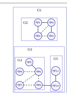
Fig. 7 shows the dependencies between operations where, dashed lines represent the indirect connections between a pair of operations and solid lines represent direct connections between them. The measurements give the following values:
– TCC(G1) = 556 = 0.10 – LCC(G1) = 6+655 = 0.21 – TCC(G2) = 36 = 0.5 – LCC(G2) = 3+26 = 0.83 – TCC(G3) = 213 = 0.14 – LCC(G3) = 3+421 = 0.33 – TCC(G4) = 101 = 0.10 – LCC(G4) = 1+4 10 = 0.5 – TCC(G5) = 11 =1 – LCC(G5) = 11 = 1
We have started with the group G1 which is not co-hesive. G1 is divided into two explicit groups (G2) and (G3). After that, (G4) and (G5) are created starting from (G3). Finally, the obtained cohesive Web services are: G2 (op1, op2, op3, op4), G4(op5, op6, op7, op8, op9) and G5( op10, op11).
G1 G2 op1 op2 op3 op4 G3 G4 op8 op5 op6 op7 op9 G5 op11 op10
Fig. 7 Example of operations grouping
4.5.2 Spreading Criterion
Similar operations are spread out in different Web ser-vices. In this way, for users of an operation within a service, another service containing a similar operation can be easily and quickly found at the same provider (reliability).
In other words, Web services are exposed to errors and failures for many reasons, such as, the network is unreachable, the application server is unavailable or the service is not working properly. Hence, the reliability of the programs (it could be an orchestration of Web services) that invokes these services will be decreased. Several error-handling approaches are proposed in the literature such as [?], [?], [?] and [?]. Many of these approaches are based on finding a relevant service sub-stitute that replaces the failed service. For example in previous works [2] and [?] the identification of the sub-stitute is based on the measurement of similarity be-tween service interfaces.
In this work, a solution based on a comparison of op-eration signatures has been used. The WSSim tool [40] allows to measure the similarity between operations by comparing the operations’ names and input and output messages. Table 1 shows the similarity measurement re-sults that are produced by WSSim for the operations that are depicted in Fig. 7. In this table we give a score of similarity (between 0 and 1) for all pairs of opera-tions. The operations that have a similarity score that ranges between 0.80 and 1 are considered highly simi-lar. According to the obtained similarity assessment, we consider that operations op8and op9are highly similar.
Table 1 Obtained similarity scores
op1 op2 op3 op4 op5 op6 op7 op8 op9 op10 op11 op1 1 0.74 0.53 0.73 0.57 0.41 0.51 0.50 0.49 0.63 0.55 op2 1 0.52 0.5 0.45 0.42 0.67 0.60 0.55 0.52 0.61 op3 1 0.53 0.55 0.61 0.70 0.70 0.56 0.38 0.50 op4 1 0.46 0.35 0.53 0.56 0.53 0.59 0.53 op5 1 0.42 0.49 0.50 0.49 0.52 0.47 op6 1 0.63 0.64 0.60 0.34 0.49 op7 1 0.76 0.79 0.38 0.51 op8 1 0.86 0.48 0.56 op9 1 0.59 0.53 op10 1 0.65 op11 1
After the calculation of cohesion and similarity be-tween the different operations, the next step is to dis-tribute these operations on Web services. In the cur-rent implementation, we assist the developer for giving a new organization based on the obtained results from the cohesion and similarity values. The proposed orga-nization could then be manually updated by the de-veloper. For example, we decide to move the operation (op8) from the Web service G4 into G5. This moving
does not have a negative impact on the cohesiveness of the obtained services.
5 Generation of composite Web Services
In this step, the potential dependencies between the different selected operations in the Web services are identified. There are two kinds of dependencies between operations: operation invocation dependencies and Web navigation relationships. The first kind of dependencies gives rise to Web service choreographies and the sec-ond to Web service orchestrations. These are detailed below:
5.1 Web Service Choreography Creation
In this step, we identify in the source code of the gener-ated Web services all external calls between operations in order to replace them by Web service requests. This is explained in Algorithm 6. If the called operations are published in the same Web service of the caller op-eration, nothing is done, the calls are left as method invocations (see Line 6). If the called operations are present in the other published Web services these oper-ation dependencies are replaced by Web service requests in source code of the invoking operation.
In the created graph for the Web service-oriented system, we represent each Web service request by a re-lationship of type W SR which relates the invoking class
node and the WSDL interface node of the invoked ser-vice (see Lines 6 to 9). An example of this relation-ship is given in Fig. 4, where the invocation to the getItemByRef erence method from the code of the op-eration serviceT otalP riceInCart is transformed into a W SR between the class CartService and the interface wsdlP roducts. As for a local method invocation, this is represented by an ISR relationship. Fig. 4 shows an ISR relationship between the CartService class and the Item class.
Algorithm 6 Web Service Choreography Creation 1: procedure createChoreographies(SOS)
2: for all op ∈ SOS do
3: for all invOp ∈ invokedOpsF rom(op)do
4: c1 =declaringClass(invOp) 5: c=declaringClass(op) 6: if c1∈ C/ s then 7: wsdl1=getServiceInterf aceOf(c1) 8: wsr = create WSR:wsr= (c WSR wsdl1) ∧ wsr ∈ Rsos
9: createW SRequest(Code(op), invOp, wsdl1)
10: end if
11: end for
12: end for
13: end procedure
Besides, other Web service requests can also be cre-ated starting from the parsing of client-side scripts. Indeed, the majority of modern Web applications use Ajax, which allows to build dynamic and interactive Web applications. Client-side scripts can create direct connections to the server and transfer data from clients to servers. The XMLHttpRequest API is the mostly used technique as an Ajax implementation [12]. In some cases, the request sent to the server asks for a server-side program which has been transformed into a Web service. We check this by the parsing of the scripts that use this API. In this case, we create a new request to this Web service. This request is added at the beginning of the source code of the Web service that is generated starting from the current Web interface. This invoca-tion allows to update the data at the server side before it will be used by the Web service.
Let us consider our illustrative example to show how to create a composite Web service at code level. In the Cart Web Interface we use a client-side script to send data to the server. Before proceeding to check-out, the user can modify the quantity of the pur-chased items. The new quantity is sent as data to the server via a client-side script (in JavaScript using an XMLHttpRequest object). This client side script con-tains a call to a program executed at the server side cor-responding to the UpdateCart Web interface. This
pro-gram allows to update the cart and calculate the new total price. When the user clicks on the proceed to checkout button, a program (provided by the Payment Web interface) is executed at the server side. This pro-gram takes as input the new calculated total price and the new cart details.
Following our approach, the payment and updateCart operations are created respectively starting from the Payment and UpdateCart Web interfaces. So, an invocation to updateCart operation is added at the beginning of the payment operation source code. In this way, the new total price is calculated before proceeding to payment.
In addition to the invocation of the updateCart op-eration several other opop-eration invocations are created in order to accomplish the payment process. Indeed, the checkCreditCard and checkPersonalInformation operations are invoked successively so that the in-put credit card information and the personal infor-mation of the user are checked. If they are valid, we call two other operations, which are approvalPayment operation to approve the payment and sendEmail operation. The approvalPayment operation itself calls some other operations, which are respectively: checkCredit, createInvoice, validatePayment and getDeliverySchedule. In this way, a choreography at code level is created for the operations that are involved in the payment activity.
5.2 Choreography Modeling
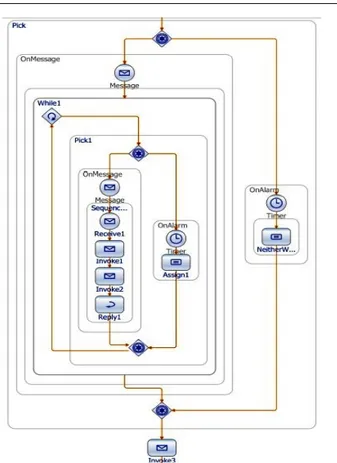
In this step of our approach, we reverse engineer the source code of the Web services to create high-level specifications in the BPMN language. This refers to the global view of the composition spanning multiple par-ticipants. We chose BPMN language because it provides a rich graphical notation for choreography modeling [9]. The creation of these choreographies helps in better un-derstanding the composition of services, which for the moment can be seen at code level only.
The generation of BPMN models is based on set of rules that we have defined as mappings between the source code elements and the BPMN elements.
– For each choreography (collaboration between ser-vices and service clients) we create a BPMN model. – Each participant (Web service or service client) in the choreography is modeled with a Pool element2.
This Pool is used as a container of the activities that are performed by the participant. The activities
rep-2 A Pool is the graphical representation of a Participant in
Fig. 8 A BPMN model representing a service choreography to accomplish the payment activity.
resent mainly the message exchanges of the service (or service client) with the others participants. – If the participant is a service client, it must thus
con-tain one or several Web service invocation(s). Each service invocation is modeled as a Task3element to be added to the created Pool element of the ser-vice client. This Task element is a kind of activities within BPMN. It is an atomic Activity within a pro-cess flow.
– The set of Tasks within a Pool are connected as a sequence (in the same order of their appearance in source code) using the Sequence Flow element. – If the participant is a Web service and it has no
requests for other services, the service is modeled as a Service Task4 element. The Service Task is a
kind of Task used to represent some sort of service, which can be a Web service.
– If the participant is a Web service and if it imple-ments requests to other services, the service is mod-eled as a SubProcess5element. The SubProcess
el-ement can be a white box or a contour which shows a lower-level process that is executed by the Web service participant. Each request to an external ser-vice is identified and modeled as a Task element to be added as an inner activity of the SubProcess el-ement. The set of Tasks within a SubProcess are
3 ATaskis a rounded corner rectangle which is drawn with
a single thin line.
4 A Service Task shares the same shape as the Task, which
is a rectangle that has rounded corners, with a graphical marker in the upper left corner of the shape that indicates that the Task is a Service Task
5 ASubProcessis an Activity whose internal details have
been modeled using Activities, Gateways, Events, and Se-quence Flows.
connected as sequence using the Sequence Flow el-ement.
– The connection between a Task element (which is generated for a service request) and the Service Task (or the SubProcess) which is located in a sep-arate pool is done via a Message Flow element. The Message Flow element is used to represent the mes-sage sending or receiving between the client and the Web service participants.
– Each control statement (for example, a conditional statement) containing a service invocation is mod-eled with a diverging Exclusive Gateway (Deci-sion) element6. It is used to create alternative paths
within a process flow, only one of the paths can be taken. Each path is targeted to an activity element or to a default path (which can be the end of the pro-cess). The decision of the Exclusive Gateway can be a question or the conditional expression which is extracted from the source code (for example, the condition expression of a conditional statement). The path where the answer to this question is true is targeted to the Task element created for the service invocation. The two elements (Exclusive Gateway and Task elements) are connected using a Sequence Flow element.
– If the service invocation statements are located within a loop statement, the loop is represented with a Loop Task element. It has the same form as the Task with a loop marker in the medium. And, we move the Task elements created for the service in-vocation statements into the Loop Task element.
6 It has the form of a diamond with a marker inside that is
Figure 8 shows the generated BPMN model7, that represents the participants services which are involved in the payment activity of the example presented pre-viously.
As we can see in this model, all the hidden chore-ographies are extracted and we can easily comprehend the behavior of the overall composition. This is due to our technique of reverse engineering, since only op-eration invocations and the control or loop statements that contain operation invocations are extracted. In this way, the developer does not need to know all the details which could be found in a large source code. Only par-ticipants (Web services) in the choreography and their exchanged messages are modeled.
By extracting this model, we believe that thanks to the high level of abstraction provided by the choreogra-phies, evolving these applications will be simpler. In-deed, we help the developer in choosing the well suited position in the code in order to apply the necessary changes to implement an evolution scenario.
Let us suppose the following evolution scenario for the payment activity choreography. We need to add a new Web service that enhances the security of the pay-ment process. This service can be a program that sends to the client a validation code with an SMS on her/his mobile phone. The client introduces the received code and the application checks its validity. On looking at the generated model, the developer can clearly decide to add an invocation to the new service after the Credit Card Authorization task in the initiating Pool.
5.3 Web Service Orchestration Creation
In this step, a set of Web service orchestrations is gener-ated from the relationships between Web interfaces. We parse navigation documents such as JSF faces-config files and their navigation rules. This allows the identifi-cation of other potential collaborations of the different Web services created from these pages.
5.3.1 Navigation Rule Extraction
In some Web applications the navigation rules are not available. In this case, the hypertext links and the redirection statements/tags located in the Web appli-cation are parsed in order to create these rules. The Web application graph could be considered as a navi-gation model for the input Web application. We asso-ciate to each Web page node a navigation condition
7 The generated model is updated and validated manually
by grouping the Pools which are of the same category and giving more readable names to Pools, Lanes (sub-partition within a Pool) andActivities.
(N C(web page)). Indeed, the redirection statements like response.sendRedirect("url") are generally de-clared in the body of a conditional statement such as If Statement. Thus, depending on the condition value, the page is redirected to the appropriate destination. The used condition in this code is extracted and ana-lyzed to be added as a condition of created navigation rule. This task requires sometimes the developer inter-vention to validate the generated navigation rules.
5.3.2 BPEL Process Creation Algorithm
The generated BPEL processes represent new services which implement some coarse grained functionalities provided by the application. The exchange of messages between the BPEL process and external clients (other applications or partner (Web) services) is done via a contract described in WSDL. This contract represents an interface of the BPEL composite Web service. Now, the generation of the Web service orchestration is im-plemented according to Algorithm 7.
In this algorithm, first all navigation paths are calculated from the Web navigation document of the parsed Web application (Line 2). Each path represents a coarse grained functionality provided to the user when (s)he navigates between the Web interfaces of this path. Therefore, for each path we create a BPEL process (Line 4) which represents a new generated Web ser-vice. After that, for each navigation rule in the current path, we identify the source operation (Line 8). The source operation corresponds to the operation that has been generated starting from the navigation’s source Web interface. The same thing is done for the des-tination Web interface (Line 19). As specified in the algorithm, a navigation rule contains three elements: i) a source view (Line 8), which represents the Web in-terface(s) from which the navigation started (e.g., the Web interface presenting the form for searching items in the example introduced previously: search.jsp); ii) a destination view (Line 19) that corresponds to the Web interface(s) to which the user will be auto-matically directed (e.g., the Web interface(s) present-ing the result of the search searchResult.jsp); and iii) an execution condition which contains an expression and a value (e.g., the expression is a call to the Jav-aBean method for getting the number of items found: #{searchResult.getItemsCount}, and the value is "NotZero").
For each navigation rule, we first test if the source operation has already been called in the process while parsing another navigation rule (Line 9). This ensures that operation invocations are not duplicated. In the case of an operation which has already been invoked in


![Larval Performance in Relation to Labile Oviposition Preference of Crocidolomia pavonana [F.] (Lepidoptera: Pyralidae) Among Phenological Stages of Cabbage](data:image/gif;base64,R0lGODlhAQABAIAAAP///wAAACH5BAEAAAAALAAAAAABAAEAAAICRAEAOw==)