O
pen
A
rchive
T
OULOUSE
A
rchive
O
uverte (
OATAO
)
OATAO is an open access repository that collects the work of Toulouse researchers and
makes it freely available over the web where possible.
This is an author-deposited version published in :
http://oatao.univ-toulouse.fr/
Eprints ID : 8678
To link to this article : DOI:10.1557/JMR.2010.0190
URL :
http://dx.doi.org/10.1557/JMR.2010.0190
To cite this version : Perre, Emilie and Taberna, Pierre Louis and
Mazouzi, Driss and Poizot, Philippe and Gustafsson, Torbjörn and
Edström, Kristina and Simon, Patrice Electrodeposited Cu2Sb as
anode material for 3-dimensional Li-ion microbatteries. (2011)
Journal of Materials Research, vol. 25 (n° 08). pp. 1485-1491. ISSN
0884-2914
Any correspondance concerning this service should be sent to the repository
administrator:
staff-oatao@listes-diff.inp-toulouse.fr
Electrodeposited Cu
2Sb as anode material for 3-dimensional
Li-ion microbatteries
Emilie Perre
Universite´ de Toulouse, CIRIMAT-UMR CNRS 5085, 31062 Toulouse Cedex 4, France; Department of Materials Chemistry, The A˚ ngstro¨m Advanced Battery Centre, Uppsala University, SE 751 21 Uppsala, Sweden; and Alistore European Research Institute, 80039 Amiens Cedex, France
Pierre Louis Taberna
Universite´ de Toulouse, CIRIMAT-UMR CNRS 5085, 31062 Toulouse Cedex 4, France; and Alistore European Research Institute, 80039 Amiens Cedex, France
Driss Mazouzi and Philippe Poizot
Alistore European Research Institute, 80039 Amiens Cedex, France; and LRCS-UMR 6007, Universite´ de Picardie Jules Verne, 80039 Amiens, France
Torbjo¨rn Gustafsson and Kristina Edstro¨m
Department of Materials Chemistry, The A˚ ngstro¨m Advanced Battery Centre, Uppsala University, SE 751 21 Uppsala, Sweden; and Alistore European Research Institute, 80039 Amiens Cedex, France
Patrice Simona)
Universite´ de Toulouse, CIRIMAT-UMR CNRS 5085, 31062 Toulouse Cedex 4, France; and Alistore European Research Institute, 80039 Amiens Cedex, France
An increasing demand on high energy and power systems has arisen not only with the development of electric vehicle (EV), hybrid electric vehicle (HEV), telecom, and mobile technologies, but also for specific applications such as powering of microelectronic systems. To power those microdevices, an extra variable is added to the equation: a limited footprint area. Three-dimensional (3D) microbatteries are a solution to combine high-density energy and power. In this work, we present the formation of Cu2Sb onto
three-dimensionally architectured arrays of Cu current collectors. Sb electrodeposition conditions and annealing post treatment are discussed in light of their influence on the morphology and battery performances. An increase of cycling stability was observed when Sb was fully alloyed with the Cu current collector. A subsequent separator layer was added to the 3D electrode when optimized. Equivalent capacity values are measured for at least 20 cycles. Work is currently devoted to the identification of the causes of capacity fading.
I. INTRODUCTION
The new powerful microelectronics need to be powered by high capacity and high rate battery systems. Today, to fulfill the needs, they are powered by oversized batteries thus restricting the potential use of these appli-cations. Thin-film microbattery is one system that has been conceived to increase reaction kinetics. Low thick-ness of the electrode and electrolyte give shorter Liþ diffusion lengths, thus enhancing the rate capability. However, as a consequence of their two-dimensional (2D) configuration (thin-films), they contain limited quantities of active material and they are unable to pro-vide as much energy as conventional batteries. Designing three-dimensional (3D) microbatteries will increase the
content of active material that can be deposited onto the same footprint area. This can be achieved by increasing the surface area of the current collector rather than the electrode film thickness, leading to batteries able to pro-vide both high specific energy output and high rate capa-bilities.1
For microelectronic applications, manufacturing proc-esses such as lithography have been developed and are now leading to high quality microfabrication. Using such processes, Min et al.2 have synthesized 3D half-microbatteries consisting of alternated arrays of carbon rods (C-MEMS) and arrays of the same carbon rods coated by polypyrol. They demonstrated better capacity per footprint area than for a conventional unpatterned battery. However, this kind of preparation includes a large amount of steps and it is costly. Soft chemistry preparation techniques such as electrodeposition, sol-gel synthesis, or electrophoresis have proved to be more
a)Address all correspondence to this author. e-mail: simon@chimie.ups-tlse.fr DOI: 10.1557/JMR.2010.0190
adapted for battery preparation. Golodnitsky et al.3have presented 3D Li-ion microbatteries consisting of succes-sive layers of each of the battery components (current collector, electrode, electrolyte) deposited onto a 3D architectured silicon substrate. The electrode material was directly electrodeposited onto the metallic current collector layer; thus, avoiding the electron percolating issue that could be encountered with thick electrodes. The cell obtained was able to sustain 100 cycles without showing considerable capacity losses.
Our approach is similar as we intend to deposit layers of the different battery components. However, in our case the three-dimensionally architectured structure is the current collector itself, thus reducing the amount of nonactive material within the microbattery. We have selected the Cu current collector since it has proved possible to grow as freestanding and ordered arrays of Cu nanorods by simple electrodeposition into a template and then to plate them with the negative electrode mate-rial Fe3O4.4 The diameter and distance between the
obtained Cu columns is directly dependent on the tem-plate used and can be easily tuned and downscaled to a few hundreds of nanometers (nm), thus increasing the total available surface area.
Regarding the active materials, metals alloying with lithium appeared to be attractive anodes as they exhibit high energy capacities but they undergo large volume variations during the alloying/dealloying processes.5,6 To circumvent these volumes changes there are several different routes: it is common to prepare nano-sized par-ticles, to disperse them in composite matrix and/or alloy them with compounds nonelectrochemically active toward lithium that will act as a mechanical buffer of the volume expansion (such as Cu2Sb, Mn2Sb, NiSn).7–10
We previously11have shown that Cu2Sb can be obtained
by electrodeposition of Sb onto a Cu flat substrate and that further heat treatment promotes alloying of Sb with Cu. The capacity retention of the electrode obtained was greatly improved when compared with pure Sb electrodes due to the ability of Cu to accommodate and buffer the volume variations of Sb.
In this work, we will show that Sb also can be uni-formly electrodeposited onto arrays of three-dimension-ally ordered Cu current collectors. The thin films thus obtained showed capacity values close to the theoretical ones and greatly increased cycle life. Direct alloying of Sb with the current collector can be profitable since the interface between the current collector and the electrode material is improved. Furthermore, it will not be neces-sary with the addition of extra inactive material to buffer the volume changes during cycling, which would greatly affect the overall battery performance, especially for a 3D microbattery configuration. The cycling perfor-mances of different deposits are presented and their electrochemical behavior discussed.
The next step for designing a microbattery is the prepa-ration of a thin and conformal separator layer. Nathan et al.12 reported the deposition of a gel polymer in the pores of a microstructured electrode to function as separa-tor and electrolyte for a 3D Li-ion microbattery. They selected an electrolyte composed of a commercially avail-able poly(vinylidene fluoride) (PVDF)-based copolymer in which SiO2particles were added. Such electrolytes are
sufficiently mechanically stable to prevent the use of a separator and present relatively high ionic conductivity (1.10–4 S.cm"1).13 Thus we selected a similar electrolyte to be used in our nanostructured 3D architecture.
Our first attempts are presented in Sec. II.
II. EXPERIMENTAL
Here, Cu nanorods have been used both as current collector and a part of the electrode itself for battery testing. The synthesis of Cu nanorods has been previ-ously described in detail by Taberna et al.4
Prior to Sb electrodeposition, the substrate was im-mersed for a few minutes in an aqueous solution of 0.5 M CuSO4# 5 H2O and 1 M H2SO4(Acros Organics,
Geel, Belgium) to remove oxide traces onto the copper surface.
Cu2Sb has been obtained in a two steps process.
Antimony has first been electrodeposited onto the Cu substrate using an Autolab PGSTAT30 potentiostat-galvanostat (Metrohm Autolab, Bromma, Sweden). The electrodeposition electrolyte consisted of a mixture of antimony tartrate and sodium tartrate (Fluka, Stockholm, Sweden) dissolved in distilled water. Sb concentration was fixed to 0.15 M and the tartrate concentration to 0.45 M. To favor the electrodeposition of Sb instead of the precip-itation of Sb2O3, the pH of the solution was decreased to 1
by addition of sulfuric acid. Current pulsed electrode-position has been selected instead of a constant current method to increase the homogeneity and conformity of the deposit. The electrodeposition conditions were fixed as follows: a current pulse was applied for a short duration (tdep) to electrodeposit Sb, a 0 mA rest period (trest) was
then applied to allow diffusion of the electroactive species to the Cu surface. The applied pulse intensities and their durations have been varied to obtain a conform deposit of Sb onto the Cu surface. Unless stated otherwise, the over-all deposition process was maintained for 2 h.
The samples were then heat-treated for various time lengths at 120 $C in a vacuum furnace with the aim of completing the alloying process.
The hybrid polymer separator was composed of 1 g of GlycioxyPropyl triMethoxySilane, 0.2 g of Poly(Vinyli-Dene Fluoride-co-HexaFluoroPropene), 30 mg of distilled water, 5 g of acetone, and 28 mg of dibutyl phthalate-DiButyl Phthalate (Aldrich, Lyon, France). The solution was sprayed onto the nanostructure and heat-treated at
120$C under vacuum for 1 h to promote polycondensation. DiButyl Phthalate was finally extracted with diethyl ether.
The morphology, homogeneity, and composition of the coatings were characterized by scanning electron microscopy (SEM; JEOL JEM200CX, Tokyo, Japan and LEO1550, Cambridge, UK), and x-ray diffraction (XRD; Siemens D5000, Toulouse, France). To evaluate their electrochemical performances, samples were cycled ver-sus lithium in a coin cell configuration. The electrolyte used was a mixture of Ethylene Carbonate:DiMethyl Carbonate with a molar ratio 1:1 containing 1 M LiPF6
salt. The current applied for electrochemical characteriza-tion was calculated by considering a 100% faradic effi-cient electrodeposition of Sb. The cycling performances, rate capabilities, and impedance of the cells were studied using VMP3 Bio-logic equipment (Claix, France).
III. RESULTS AND DISCUSSION A. Sb-coated Cu 3D electrode arrays
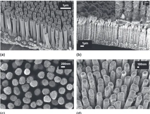
Pulsed current electrodeposition rather than galvano-static deposition was selected to promote good diffusion of the species to be deposited into the narrow 3D structure. Pulse parameters such as deposition current and pulse time lengths were varied. Whatever the duration and current of the pulses, the occurrence of a deposit on the copper rods was clearly observed with SEM [Fig. 1(a) versus Figs. 1(b)–1(d)]. However, the morphology and coverage of the deposited material were directly related to the electrodeposition conditions.
Even though full coverage of the Cu arrays by Sb was successfully obtained when applying 2-mA pulses [Fig. 1(b)], an inhomogeneous deposit morphology was observed due to diffusion limitations. The Sb deposit agglomerated on the nanorod tips, while large crystallites were formed at the bottom between the pillars.
When using equivalent time steps,tdep¼ trest¼ 50 ms
and lower applied current (1 mA) during the depo-sition step, the Sb deposit appeared more homogeneous [Fig. 1(c)]. When the deposition time was lower than the rest period,tdep¼ 10 ms < trest¼ 50 ms [Fig. 1(d)],
the deposit appeared very homogeneous and smooth. Smaller particles were deposited than when the depo-sition and rest periods were equivalent.
The deposit was characterized by XRD and shown to be a mixture of Sb and Cu2Sb. Alloying of Sb with Cu
happened spontaneously at room temperature, as already reported by Bryngelsson et al.11
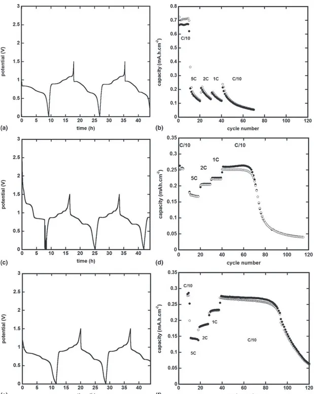
The different samples were subsequently cycled ver-sus lithium to study the influence of the different deposition parameters on their battery performances: reversibility, capacity, and cycling capability. For each electrode, the applied cycling current was determined based on the expected deposited weight of Sb consider-ing a 100% faradic efficiency Sb electrodeposition. The first cycles and the capacity retention of the cycled sam-ples are presented in Fig. 2.
Galvanostatic curves obtained versus lithium con-firmed the spontaneous formation of the alloy Cu2Sb.
The profile of the obtained cyclings [Figs. 2(a), 2(c),
FIG. 1. (a) SEM micrograph of a raw Cu nanorods array and Sb electrodeposited onto arrays of Cu nanorods using different pulse conditions. (b)"2 mA for 100 ms and rest for 50 ms steps applied for 2 h, inset: zoom on the bottom part of the 3D nanostructure, (c) "1.3 mA for 50 ms and rest for 50 ms steps applied for 2 h, (d)"1.3 mA for 10 ms and rest for 50 ms steps applied for 2 h.
and 2(d)] corresponds to the reactions previously described by Fransson et al.14where lithium alloys with Cu2Sb according to the following reactions.
Cu2Sbþ 2Li $ Li2CuSbþ Cu ; ð1Þ
Li2CuSbþ Li $ Li3Sbþ Cu : ð2Þ
Reaction (1) can be divided into two steps that have been expressed differently by Morcrette et al.15 [see reactions (3) and (4)] and Matsuno et al.16[see reactions (5) and (6)]. The variation concerned the amount of Cu extruded during those two reactions.
Cu2Sbþ ð2 " xÞLi $ Li2"xCu1þxSbþ ð1 " xÞCu ; ð3Þ
FIG. 2. Capacity retention and cycling curves (first cycles) of Sb electrodeposited onto Cu nanorod arrays at different conditions: (a, b)"1.3 mA for 50 ms and rest for 50 ms steps applied for 2 h, (c, d)"1.3 mA for 10 ms and rest for 50 ms steps applied for 2 h, (e, f) "1.3 mA for 10 ms and rest for 50 ms steps applied for 2 h, then heat-treated at 120$C for 1 h.
Li2"xCu1þxSbþ xLi $ Li2CuSbþ xCu ; ð4Þ
or
Cu2Sbþ ð2 " xÞLi $ Li2"xCuSbþ Cu ; ð5Þ
Li2"xCuSbþ xLi $ Li2CuSb : ð6Þ
The 3-step process observed on cycling was less visi-ble during the first discharge; probably due to the forma-tion of a solid-electrolyte interphase (SEI) layer thus masking the lithiation processes.11 During the next cycles, the curve profile was characteristic for Cu2Sb
cycling versus lithium for all the half-cells tested where the 3-step reaction is clearly seen during the delithiation process.12The potential values observed for each step were independent of the synthesis conditions and corresponded to the potential values reported by Bryngelsson et al.11
However, the capacity retention of the obtained arrays of electrodes obtained was found to be dependent on the electrodeposition conditions. Better capacity retention was observed for deposits made under the following pulsed conditions: "1.3 mA for 10 ms and a resting period of 50 ms at 0 mA [Fig. 2(f)]. An increase of the current density during the Sb deposition step led to poor capacity retention independent of the applied cycling rate [Fig. 2(b)]. This behavior was linked to the deposit morphology characterized, in that case, by bigger parti-cles and nonconformal deposit of Sb onto the Cu rods [Fig. 1(b)]. A decrease of the deposition-step time versus the rest-step time (10 ms versus 50 ms) led to better capacity retention [Fig. 2(d)], probably due to the en-hanced homogeneity of the coating, especially at the bottom of the Cu rod arrays. The capacity decay observed after 60 cycles can be ascribed to the presence of pure Sb. Because Sb endures a large volume expansion during lithiation, the appearance of cracks and loss of contact in some parts of the coating is then more likely.
To promote full alloying of Sb with Cu, a heat treat-ment was performed after a 1 h Sb electrodeposition. The obtained electrode was tested versus lithium. The first cycles and capacity as a function of the number of cycles were plotted in Figs. 2(e) and 2(f). The charge–discharge profile curve was similar to the curve previously pre-sented. Nevertheless, while maintaining the same capac-ity values, the capaccapac-ity retention was greatly enhanced. The reason for such an increase was attributed to an increase of the mechanical buffering capacity of the Cu matrix around the Sb.
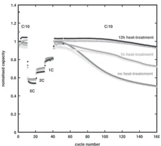
As the heat-treatment time was increased, the capacity retention was enhanced (Fig. 3). The formation of the Cu9Sb2 alloy previously reported by Bryngelsson
11
was not electrochemically observed even after a 12 h heat treatment. The temperature was probably not high enough to favor the structural formation of Cu9Sb2after 12 h.
Cycling rate has been varied on cycling for the differ-ent Cu2Sb arrays to monitor the efficiency of the deposits
as battery material. All samples synthesized with an electrodeposition step of"1.3 mA were able to recover their initial C/10 capacity after a series of 10 cycles at 5, 2, and 1 C. The high cycling rate stability confirms the great power capability of these kinds of 3D electrodes.
B. Hybrid polymer separator
The next critical step in the synthesis of 3D micro-batteries was the preparation of a thin, conformal and pine-hole-free layer of separator. The separator synthesis was studied using Cu2Sb 3D arrays obtained after a 2 h
pulsed electrodeposition of Sb ("1.3 mA for 10 ms—rest for 50 ms) followed by a 12 h heat treatment at 120$C under vacuum.
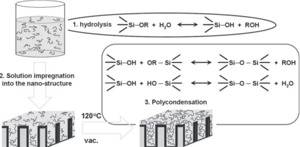
The separator synthesis and insertion into the 3D electrode was realized in three steps (Fig. 4): The mono-mer and additives where dissolved in acetone, the obtained solution was sprayed onto the 3D electrode, which was then heat-treated at 120 $C for 1 h under vacuum to favor polycondensation. The spray and poly-condensation steps were repeated up to 3 times to vary the separator thickness.
A top view of the obtained deposit is presented in Fig. 5. The roughness observed corresponded to distinct groups of nanorods being separated by the thickest layer of polymer. The presence of a separator along all the rods and deep down in the arrays could not be confirmed.
To demonstrate the ability of the coating to be an ionic conductor but electronically insulating, the obtained electrodes were electrochemically tested versus lithium without any additional porous separator. Accordingly,
FIG. 3. Capacity retention of Sb electrodeposited onto arrays of Cu nanorods at"1.3 mA for 10 ms and rest for 50 ms steps applied for 1 h, followed by a heat treatment at 120$C.
the lithium anode was directly plated onto the separator coating.
No drastic change in the cycling behavior was observed as a function of the separator thickness (Fig. 6). In both cases, no short-circuit of the electrodes was observed and cycling curves showed plateaus corresponding to the same Cu2Sb lithium alloying/dealloying reactions.
However, when compared to the Cu2Sb electrodes tested
previously, the capacity values (0.22 mAh.cm"2instead of 0.26 mAh.cm"2) and cell stability were decreased on cycling (20 cycles instead of 120). The cause for capacity fading could be attributed to various phenomena such as chemical or electrochemical degradation of the separator, existence of water linked in the hybrid polymer structure or an incomplete polycondensation step leading to loss of mechanical strength. Preliminary infrared (IR) and thermogravimetric analysis (TGA)/differential scanning calorimetry (DSC) results did not, however, confirm the presence of water in the structure. The irreversible capac-ity measured on first cycle is larger than the values mea-sured for the arrays of Cu/Cu2Sb only, thus suggesting
a possible reaction of the separator with the electrode/ electrolyte interface.
IV. CONCLUSION
We showed that it is possible to electrodeposit anti-mony onto a complex 3D structure of Cu current collec-tors and form Cu2Sb by annealing of the structure. The
FIG. 5. SEM micrograph of Cu2Sb covered by one sprayed layer of polymer separator.
FIG. 4. Schematic diagram of separator preparation and impregnation in the Cu2Sb 3D electrode.
FIG. 6. The capacity retention for Cu2Sb arrays covered by one or three sprayed layers of polymer separator. The inset shows the first two cycles.
process presents several advantages. Electrodeposition is a versatile and soft synthesis technique. No addition of extra copper for alloying or carbon black/binder used in the standard electrode slurry was required. Thus, the number of parameters that influence the elec-trode cycling behavior are reduced. The amount of nonelectrochemically active material is also reduced, which in the case of microbatteries is an essential param-eter. The behavior, when cycling of the so-obtained composite current-collector/electrode nanorods, is in accordance with the results presented by Bryngelsson et al.11 Moreover, the capacity per footprint area when compared to a thin film 2D electrode is increased as previously demonstrated by Taberna et al.4
Deposition of a hybrid polymer separator layer by spray deposition did not lead to the formation of a thin and conformal layer onto the arrays of electrode. How-ever, we showed that the thin layer deposited on the complex architecture was sufficient enough to avoid short circuiting of the cell. Even though the causes of capacity fading on cycling are not yet identified, the first results obtained so far are promising. Currently, work is being done to go toward a better understanding of the reactions occurring. Thus, it would be possible to improve polymer separator characteristics and cycling performances.
ACKNOWLEDGMENTS
This work was supported by the Alistore European Research Institute (ERI), the Swedish Research Council (VR), SUPERLION within EU-FP7 under the Grant Agreement No. 214832-2. We also acknowledge the French Ministry of Research for the Ph.D. grant of Emilie Perre.
REFERENCES
1. J.W. Long, B. Dunn, D.R. Rolison, and H.S. White: Three-dimensional battery architectures.Chem. Rev. 104, 4463 (2004). 2. H-S. Min, B.Y. Park, L. Taherabadi, C. Wang, Y. Yeh, R. Zaouk,
M.J. Madou, and B. Dunn: Fabrication and properties of a carbon/
polypyrrole three-dimensional microbattery. J. Power Sources 178, 795 (2008).
3. D. Golodnitsky, V. Yufit, M. Nathan, I. Shechtman, T. Ripenbein, E. Strauss, S. Menkin, and E. Peled: Advanced materials for the 3d microbattery.J. Power Sources 153, 281 (2006).
4. P.L. Taberna, S. Mitra, P. Poizot, P. Simon, and J.M. Tarascon: High rate capabilities Fe3O4-based Cu nano-architectured elec-trodes for lithium-ion battery applications.Nat. Mater. 5, 567 (2006).
5. R. Nesper: Structure and chemical bonding in zintl-phases containing lithium.Prog. Solid State Chem. 20, 1 (1990). 6. L.Y. Beaulieu, K.W. Eberman, R.L. Turner, L.J. Krause, and
J.R. Dahn: Colossal reversible volume changes in lithium alloys. Electrochem. Solid-State Lett. 4, A137 (2001).
7. J.O. Besenhard, J. Yang, and M. Winter: Will advanced lithium-alloy anodes have a chance in lithium-ion batteries?J. Power Sources 68, 87 (1997).
8. A.S. Arico, P. Bruce, B. Scrosati, J.M. Tarascon, and W. Van Schalkwijk: Nanostructured materials for advanced energy con-version and storage devices.Nat. Mater. 4, 366 (2005).
9. M.M. Thackeray, J.T. Vaughey, C.S. Johnson, A.J. Kropf, R. Benedek, L.M.L. Fransson, and K. Edstrom: Structural consid-erations of intermetallic electrodes for lithium batteries.J. Power Sources 113, 124 (2003).
10. K.D. Kepler, J.T. Vaughey, and M.M. Thackeray: LixCu6Sn5 (0 <x < 13): An intermetallic insertion electrode for recharge-able lithium batteries. Electrochem. Solid-State Lett. 2, 307 (1999).
11. H. Bryngelsson, J. Eskhult, L. Nyholm, and K. Edstro¨m: Thin films of Cu2Sb and Cu9Sb2as anode materials in Li-ion batteries. Electrochim. Acta 53, 7226 (2008).
12. M. Nathan, D. Golodnitsky, V. Yufit, E. Strauss, T. Ripenbein, I. Shechtman, S. Menkin, and E. Peled: Three-dimensional thin-film Li-ion microbatteries for autonomous mems. J. Micro-electromech. Syst. 14, 879 (2005).
13. J.Y. Song, Y.Y. Wang, and C.C. Wan: Review of gel-type poly-mer electrolytes for lithium-ion batteries.J. Power Sources 77, 183 (1999).
14. L.M.L. Fransson, J.T. Vaughey, R. Benedek, K. Edstrom, J.O. Thomas, and M.M. Thackeray: Phase transitions in lithiated Cu2Sb anodes for lithium batteries: An in situ x-ray diffraction study.Electrochem. Commun. 3, 317 (2001).
15. M. Morcrette, D. Larcher, J.M. Tarascon, K. Edstrom,
J.T. Vaughey, and M.M. Thackeray: Influence of electrode micro-structure on the reactivity of Cu2Sb with lithium.Electrochim. Acta 52, 5339 (2007).
16. S. Matsuno, M. Noji, T. Kashiwagi, M. Nakayama, and M. Wakihar: Construction of the ternary phase diagram for the Li–Cu–Sb system as the anode material for a lithium ion battery. J. Phys. Chem. C 111, 7548 (2007).