m UNIVERSITÉ DE
la SHERBROOKE
Faculté de génieDépartement de génie chimique
IN SITU PURIFICATION IN LARGE-SCALE PRODUCTION OF SINGLE-WALLED CARBON NANOTUBES BY INDUCTION THERMAL PLASMA
PURIFICATION IN SITU DURANT LA SYNTHÈSE DE NANOTUBES DE
CARBONE MONOPAROI À GRANDE ECHELLE EN UTILISANT UN PLASMA
THERMIQUE INDUCTIF
Maîtrise es sciences appliquées Spécialisation : Génie chimique
Composition du jury Rapporteur Correcteur Correcteur Directeur du mémoire Ali SHAHVERDI
Sherbrooke, (Québec), CANADA Janvier 2008
B. Marcos J. Jurewicz
T. Coyle G. Soucy
?F?
Library and Archives Canada Published Heritage Branch 395 Wellington Street OttawaONK1A0N4 Canada Bibliothèque et Archives Canada Direction du Patrimoine de l'édition 395, rue Wellington Ottawa ON K1A 0N4 CanadaYour file Votre référence ISBN: 978-0-494-65604-4 Our file Notre référence ISBN: 978-0-494-65604-4
NOTICE: AVIS:
The author has granted a
non-exclusive license allowing Library and Archives Canada to reproduce, publish, archive, preserve, conserve, communicate to the public by
telecommunication or on the Internet, loan, distribute and sell theses worldwide, for commercial or
non-commercial purposes, in microform, paper, electronic and/or any other
formats.
L'auteur a accordé une licence non exclusive
permettant à la Bibliothèque et Archives Canada de reproduire, publier, archiver, sauvegarder, conserver, transmettre au public par télécommunication ou par l'Internet, prêter, distribuer et vendre des thèses partout dans le
monde, à des fins commerciales ou autres, sur
support microforme, papier, électronique et/ou
autres formats.
The author retains copyright ownership and moral rights in this
thesis. Neither the thesis nor
substantial extracts from it may be
printed or otherwise reproduced without the author's permission.
L'auteur conserve la propriété du droit d'auteur et des droits moraux qui protège cette thèse. Ni
la thèse ni des extraits substantiels de celle-ci
ne doivent être imprimés ou autrement reproduits sans son autorisation.
In compliance with the Canadian Privacy Act some supporting forms may have been removed from this
thesis.
Conformément à la loi canadienne sur la
protection de la vie privée, quelques
formulaires secondaires ont été enlevés de cette thèse.
While these forms may be included in the document page count, their removal does not represent any loss
of content from the thesis.
Bien que ces formulaires aient inclus dans la pagination, il n'y aura aucun contenu
manquant.
¦?¦
To my parents
To my sister, Kiana
RESUMÉ
Les nanotubes de carbone monoparoi (en anglais : single-walled carbon nanotubes, SWCNTs) sont les nouvelles formes de nanostructure de carbone qui possèdent des propriétés physiques et
chimiques importantes pour les applications avancées, y compris les dispositifs
micro-électroniques, les transistors nanométriques, les supports des catalyseurs, les biocapteurs et lesrenforcements des matériaux, la chimie médicale, etc.
Actuellement, différentes méthodes ont été utilisées pour la synthèse de SWNCTs. Toutes ces
méthodes produisent des SWCNTs avec des sous-produits tels que le carbone amorphe, les
fullerènes, les graphites nanocristallins, les nanotubes de carbone multiparoi et les métaux de transition. Pour améliorer les propriétés physiques de SWNCTs et pour étudier les possibilités de fonctionnalition chimique, il est avantageux de travailler avec un matériel qui soit aussi pur que possible.Ce travail concerne la purification in situ de la suie de SWCNTs produite en grande échelle (par
exemple, le taux de production de ~ 100 g h"1) par le système de plasma inductif thermique. Les
objectifs principaux de cette recherche sont les suivants : 1) éliminer les carbones amorphes
résiduels de SWCNT produits dans le système plasma inductif, 2) étudier l'effet de débit de gazoxydant et la température dans le processus de purification.
La méthode utilisée dans le plan expérimental est basée sur l'oxydation thermique sélective en phase gazeuse de la suie de SWCNTs. Le montage expérimental peut être présenté séparément
de la manière suivante : 1) système de synthèse se compose d'un réacteur à paroi refroidie équipé
d'une torche à plasma inductif par haute fréquence de 3 MHz avec un système de filtration, 2) le
système de purification qui comprend un four et d'un réchauffeur de gaz pour contrôler la
température des gaz oxydants, et le système de filtration où l'oxydation thermique de la suie
produite se déroule.La suie de SWCNTs a été produite par le système d'induction de plasma thermique, en utilisant
un mélange de noir de carbone (Raven 860 ultra) comme une source de carbone et le nickel (Ni),
le cobalt (Co) et l'oxyde d'yttrium (Y2O3) qui sont utilisés comme catalyseurs. Une série
d'expériences a été complétée afin d'évaluer la capacité du processus d'oxydation thermique de la suie de SWCNTs. Pendant la synthèse et des procédés de purification, la température le long du système de filtration a été mesurée. Deux types de gaz oxydants (l'air et l'oxygène) ont été injectés dans le système de filtration. Les échantillons purifiés ont été caractérisés par différentes techniques telles que la microscopie électronique à balayage haute résolution (HRSEM), le
microscope électronique en transmission (MET), l'analyse thermo-gravimétrique (TGA) (en
anglaise : thermo-gravimetric analysis) et la spectroscopie Raman.Les résultats ont indiqué que l'élimination in situ de carbone amorphe de la suie de SWCNTs produite par le plasma d'induction thermique a été réalisée avec succès (une pureté de plus de 60 wt% a été atteinte). De plus, l'oxydation thermique de la suie amène à une distribution plus étroite de diamètre de tubes dans les échantillons purifiés.
En considérant les résultats présentés dans cette étude, les prochains travaux devront s'attarder à mieux comprendre les mécanismes de réaction entre la suie de SWCNTs et l'oxygène. En s' appuyant sur les résultats obtenus, les travaux supplémentaires comme la modification du système de filtration (c'est-à-dire, la chambre de collecte, d'un filtre à air...) doivent être réalisés afin de mieux réaliser la purification in situ. Différents gaz peuvent être également introduits dans le système de filtration pour améliorer les processus de purification ainsi qu'une meilleure élimination des particules de catalyseurs. Nos résultats révèlent que le présent système de synthèse a une capacité de fonctionnalition in situ des tubes. Par conséquent, selon le type de groupes fonctionnels désirés, le gaz approprié pourra être injecté dans le système de filtration.
Mots-clés : Nanotubes de carbone monoparoi (SWCNT), Plasma inductif thermique, Purification
in situ, Oxydation thermique sélective
ABSTRACT
Single-walled carbon nanotubes (SWCNTs) are new forms of carbon nanostructure that have exhibited important physical and chemical properties with a wide range of future applications including microelectronic devices, nanoscale transistors, catalyst supports, biosensors, reinforcement materials, medical chemistry, etc.
Up to now, many versatile methods have been used for SWNCT synthesis. These methods can produce SWCNT besides many by-products such as amorphous carbon, fullerenes, nanocrystalline graphite and multi-walled carbon nanotubes. For the exploration of the physical properties of SWNCT and to investigate the possibilities of chemical functionalization it is advantageous to work with a material that is as pure as possible.
The work presented here is focused on in situ purification of SWCNT soot synthesized by a
large-scale (i.e., production rate of -100 g h"1) induction thermal plasma process. The main
objectives of this research are: 1) to get rid of amorphous carbon impurities from SWCNT soot produced in the induction thermal plasma system, 2) to study the effect of oxidizing gas flow rate (i.e. oxygen) and temperature on the purification process.
The methodology used in this experimental design is based on gas-phase thermal oxidation of synthesized SWCNT soot. The experimental apparatus can be divided in to two parts as follows: 1) synthesis system which consists of a flow type reactor equipped with a high frequency plasma
torch operated at 3 MHz along with quenching and filtration systems 2) purification system
which consists of an oven and a gas heater used to control the temperature of oxidizing gases, and a filtration system where thermal oxidation of the synthesized soot takes place.SWCNT soot was synthesized by an induction thermal plasma process using a mixture of carbon black (Raven 860 ultra) as a carbon source and nickel (Ni), cobalt (Co) and yttrium oxide (Y2O3)
as catalysts. A series of preliminary experimental tests was conducted to evaluate the process
ability to purify SWCNT soot in situ using a gas-phase thermal oxidation process. In these tests,
temperature measurements along the filtration system were carried out during synthesis and
purification processes. Two types of oxidizing gases (i.e., air and oxygen) were injected into the
filtration system and the purified samples were characterized by different powerful techniques such as high resolution scanning electron microscopy (HRSEM), transmission electron microscopy (TEM), thermo-gravimetric analysis (TGA) and Raman spectroscopy.
The results indicated that in situ removal of amorphous carbon from SWCNT soot synthesized
by induction thermal plasma can be successfully achieved (a purity of more than 60 wt% ofSWCNTs was achieved). Moreover thermal oxidation of the soot causes a narrower distribution
of tube diameters in the purified sample.
Overall, the findings of this study are relevant to the purification process technology of SWCNTs and future research is proposed to fully understand the reaction mechanism of SWCNT soot by oxygen. Based in the results of this work, additional work using a modification of the filtration system (i.e., collection chamber and filter tubes) should be performed in order to get rid of other
carbonaceous impurities. Different gases can be also introduced in to the filtration system to
improved the purification process and extend it for removal of catalysts particles. Our findings reveal that the present synthesis system has a capability for functionalization of tubes in situ. Therefore according to the type of functional groups which are desired to be attached to the tubes, proper gases can be injected into the filtration system.Key words: Single-walled carbon nanotube (SWCNT), Induction thermal plasma, In situ
purification, Selective thermal oxidationACKNOWLEDGEMENTS
I would like to thank, firstly, my research director, Professor Gervais Soucy, without whose
support and guidance and advice this research project would have never been completed.
I would like to thank all my colleagues who helped me during this work, especially Keun Su Kim and Yasaman Alinejad, whose assistance and guidance helped me a lot.
I would like to thank National Research Council of Canada (NRC) which helped me a lot for the beginning of this project.
I would like to thank the reviewers committee of this work for their excellent comments.
I wish to thank all people who helped me during the experimental part of this work. Particularly, Serge Gagnon, and Marc Couture.
I wish to thank all IMSI members, in particular Stéphane Gutierrez who helped me a lot during the characterization part of this work.
Lastly, I would like to express all my love and gratitude to my parents and my sister for being always next to me.
TABLE OF CONTENTS
RESUME
i
ABSTRACT iii AKNOWLEDGMENT ? TABLE OF CONTENTS vi LISTOFFIGURES ?LIST OF TABLES xiv
CHAPTERl INTRODUCTION 1
1.1 Carbon nanotubes 1
1.2 Single-walled carbon nanotubes synthesis 2
1.3 In situ purification of single-walled carbon nanotubes 3
3.1.1 Energy saving 4
3.1.2 Time saving 4
3.1.3 Lower operating cost 5
CHAPTER 2 LITERATURE REVIEW 6
2.1 Liquid phase purification 6
2.2 Gas phase purification 8
CHAPTER 3 EXPERIMENTAL SET UP, PROCEDURE AND CHARACTERIZATION
TECHNIQUES 12
3.1
Synthesis of SWCNTs by induction thermal plasma
12
a) Reactor 14 b) Quenching section 14 c) Collection chamber 15 d) Graphite lining 15 e) Operating conditions 15 3.2 In situ purification 16 3.2.1 Experimental equipments 17 3.2.2 Experimental set up 19 3.3 Chemicals 20 3.4 Characterization techniques 21 3.4.1 Raman Spectroscopy 21
a) Operating conditions of Raman analysis 24
b) Data processing 24
3.4.2 Thermo-gravimetric analysis (TGA) 24
3.4.3 High resolution scanning electron microscopy (HRSEM) 26
3.4.4 Transmission Electron Microscopy (TEM) 27
3.5 Sample collection and preparation procedure 27
3.5.1 Sample collection method 27
3.5.2 Sample preparation procedure 30
a) High Resolution Scanning Electron Microscopy (HRSEM) 31
e) Thermo-gravimetric Analysis (TGA) 32
d) Raman spectroscopy 32
e) X-ray diffraction (XRD) 32
CHAPTER 4 RESULTS AND DISCUSSION 34
4.1 Material characterization 34
4.1.1 Oxidation study of carbon black 38
4.2 In situ purification problems 41
4.3 Offline purification 44
4.4 In situ purification by air 46
4.5 In situ purification by oxygen 51
4.5.1 In situ purification by 5 vol% of oxygen 52
a) Raman spectroscopy 53
b) HRSEM analysis 55
c) Thermo-Gravimetric Analysis (TGA) 56
4.5.2 In situ purification by 7.5 vol% O2 andlOvol%02 57
a) Raman spectroscopy 59
b) Thermo-gravimetric analysis 62
c) TEM analysis 66
4.6 Effect of temperature 68
4.7 Reduced diameter distribution of single-walled carbon nanotubes
CONCLUSIONANDRECOMMENDATIONS 73
LIST OF FIGURES
Figure 1.1
Main forms of carbon nanotubes (a) Single wall carbon nanotubes (b) multi wall
carbon nanotubes 2
Figure 2.1 Schematic diagram of the apparatus used for thermal annealing in the air 9 Figure 3.1 Experimental Induction Plasma system used to synthesize SWCNTs 13 Figure 3.2 Scheme of induction plasma torch (Tekna PL-50) and probe positioned at the
center of plasma torch 13
Figure 3.3 Scheme of the gas heater used during in situ purification of SWCNTs to
preheat the oxidizing gases such as air and oxygen 17 Figure 3.4 The gas heater used during in situ purification. A thermocouple was placed at its
exit to monitor the outlet gas temperature 17
Figure 3.5 Photo of the gas distributor used for in situ purification of SWCNTs a) upper
view b) side view c) a hole on the distributor 18
Figure 3.6 Experimental set up of SWCNT synthesis and in situ purification system 19 Figure 3.7 Raman spectrum showing the most characteristic features of CNTs: radial
breathing mode (RBM), the D-band, G-band and G '-band. Second order modes
are also observed 23
Figure 3.8 A typical TGA/DTG profile of as-produced SWCNT soot synthesized by induction
thermal plasma process 25
Figure 3.9 The 3-D scheme of collection chamber and filter tubes used to collect SWCNTs synthesized by induction thermal plasma from exhausted gases 28 Figure 3.10 Temperature profile along the collection chamber during SWCNTs synthesis
Figure 3.11
Scheme of the collection chamber and its geometry along with the position of the
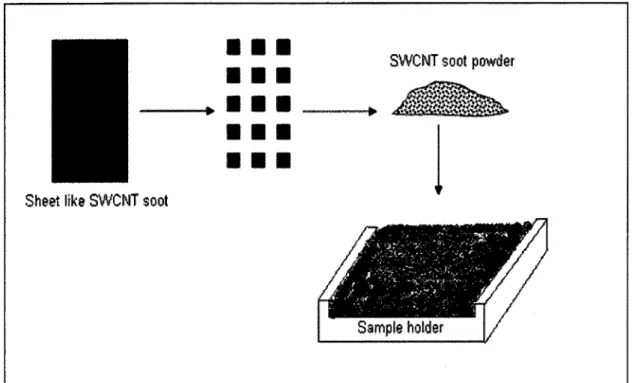
samples collected from sheet like SWCNT soot for characterization techniques
such as TEM5HRSEM, TGA and Raman spectroscopy 30
Figure 3.12
Schematic procedure used to prepare samples of SWCNTs sheet like soot
for XRD analysis 33
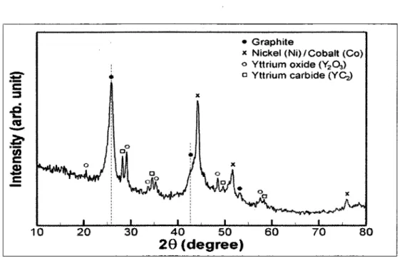
Figure 4. 1
X-ray diffraction pattern of the raw soot containing SWCNTs synthesized by
induction thermal plasma process 35
Figure 4.2 TGA curve of the SWCNT soot produced by induction thermal plasma which is recovered from collection chamber exhibits several stepwise weight-losses 36
Figure 4.3
DTG curve and Lorentzian fits of as-produced SWCNT soot synthesized by
induction thermal plasma process 37
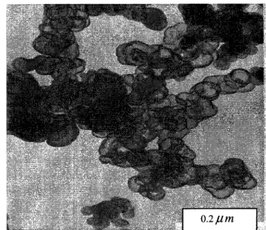
Figure 4.4 Transmission electron micrograph showing hollow particles of carbon black
following severe thermal oxidation 38
Figure 4.5 Model indicating cutaway view of single carbon black particle 39 Figure 4.6 Transmission electron microphage showing hollow particles inside the in situ
purified SWCNT sample 39
Figure 4.7 Comparison between TGA graphs of the raw SWNT soot and feedstock material
of carbon black (Raven 860) 40
Figure 4.8 Distributions of (a) temperature and (b) streamlines inside the reactor calculated
from the 2D thermal flow simulation 42
Figure 4.9 Scheme of the SWCNT synthesis system and the installed thermocouples into
the collection chamber to measure the temperature profile 43 Figure 4. 10 Temperature profile inside the connector tube and collection chamber during
SWCNT synthesis process 44
Figure 4. 1 1
Scheme of the apparatus used for offline purification of SWCNT soot
Figure 4.12
Temperature profile along the collection chamber measured by K-type
thermocouples during in situ purification of SWCNT soot by air 47
Figure 4. 1 3
HRSEM pictures of a) unpurified SWCNT soot b) in situ purified SWCNT
soot by injection of room temperature air 48
Figure 4.14 Temperature profiles along the collection chamber during in situ purification
process 50
Figure 4.15
Temperature profile along the collection chamber during in situ purification of
SWCNT soot by 5 vol% O 2 52
Figure 4. 16 Raman spectrum of in situ purified SWCNT soot by 5 vol% O 2 along with that
of unpurified SWCNT soot 53
Figure 4. 17
Disorder-induced D-band spectra from Raman analysis of a) unpurified
SWCNT soot b) in situ purified SWCNT soot by 5 vol% O2 54 Figure 4. 1 8 HRSEM images of SWCNT: a) before purification (as-produced SWCNT soot
by induction thermal plasma), b) after in situ purification process by 5%0 2
55
Figure 4. 19 TGA graphs of raw SWCNT soot (dash-line) and in situ purified SWCNTsoot (solid-line) 56
Figure 4.20 Temperature profiles during in situ purification along the collection chamber 58 Figure 4.21 Raman spectra of in situ purified SWCNT soot samples along with that of
unpurified SWCNT soot 60
Figure 4.22 Disorder-induced D-band spectra from Raman analysis of a) unpurified
SWCNT soot b) in situ purified SWCNT soot by 5 vol% O2 c) in situ purified
SWCNT soot by 7.5 vol% O2 d) in situ purified SWCNT soot by 10 vol% O 2
61
Figure 4.23 HRSEM images of in situ purified SWCNT soot by 10 vol% O 2 a) lowmagnification b) high magnification
62
Figure 4.24
TGA profiles of the purified SWCNT samples by thermal oxidation process
63
Figure 4.26
HRSEM image of SWCNT soot in situ purified by thermal oxidation
process at an oxygen flow rate of 17.22 SLPM(IO vol%) 66
Figure 4.27
TEM images of the SWNT materials produced by the induction thermal plasma
process: (a) raw SWNT soot, (b) after in situ purification (10 vol% O2) 67 Figure 4.28 Scheme of the collection chamber along with HRSEM images of the in situ
purified SWCNTs soot: (a) purified sample collected from upper part (b)
purified sample collected from middle (c) purified sample collected from bottom..68 Figure 4.29 Low-frequency region of Raman spectrum obtained with as-produced
SWCNTs soot 69
Figure 4.30 Low-frequency region of Raman spectrum obtained with in situ purified
SWCNT soot by 5 vol% O2 70
Figure 4.3 1 Low-frequency region of Raman spectrum obtained with in-situ purified
SWCNT soot by 7.5 vol%02 71
Figure 4.32 Low-frequency region of Raman spectrum obtained with in-situ purified
LIST OF TABLES
TABLE 3.1 OPERATING CONDITIONS OF THE SYSTEM USED TO PRODUCE
SWCNT IN LARGE SCALE BY INDUCTION THERMAL PLASMA 16
TABLE 3.2 FEEDSTOCKS OF SWCNT PRODUCTION 20
TABLE 4. 1 RESULTS OF OFFLINE PURIFICATION AFTER 30 MINUTES AT THREE
DIFFERENTTEMPERATURES 45
TABLE 4.2 RESULTS OF OFFLINE PURIFICATION AT 3500C AFTER 30 AND 60
CHAPTERl INTRODUCTION
1.1 Carbon nanotubes
" Carbon nanotubes are unique nanostrucîures with remarkable electronic and mechanical properties, some stemming from the close relation between carbon nanotubes and graphite, and some from their one dimensional aspects.'''' [Dresselhaus
et a/, 2001]
Since their discovery in the early 1990s, carbon nanotubes have been of great interest, both for the elucidation of fundamental one-dimensional science and for a wide variety of potential application [O'Connell, 2006], including:
• Materials
- Chemical and biological separation, purification, and catalysis
- Energy storage such as hydrogen storage, fuel cells, and the lithium battery - Composites for coating, filling, and structural materials
- Reinforcements
• Devices
- Probes, sensors, and actuators for molecular imaging, sensing, and manipulation - Transistors, memories, logic devices, and other nanoelectronic devices
- Field emission devices for x-ray instruments, flat panel display, and other vacuum nanoelectronic applications. [Meyyappan et at, 2005]
This allotrope of carbon (CNTs) can be viewed as a hollow cylinder formed by rolling graphite
sheet. Bonding in carbon nanotubes is essentially sp2 which is like that in graphite. However
p bond is more delocalized outside the tubes. This make nanotubes mechanically stronger,
electrically and thermally more conductive, and chemically and biologically more active than
graphite [Meyyappan et at, 2005]. There are two main types of carbon nanotubes as follows:
1- Single-walled carbon nanotubes (SWCNTs) consist of just one layer of graphite sheet.
2- Multi wall carbon nanotubes (MWCNTs) consist of more than two layers.^r
fi liuffMSftí
ISlSSS
(b)
Figure 1 . 1 Main forms of carbon nanotubes (a) Single-wall carbon nanotubes (b) multi-wall carbon nanotubes [from Daenen et at, 2003]
SWCNTs have more distinctive electrical and optical properties when they are compared to MWCNTs and are typically used in electronic components because unlike MWCNTs, the atoms of SWCNTs form a single covalently bound array [Baddour et at, 2005].
1.2 Single-walled carbon nanotubes synthesis
Since their first discovery in 1993 [Ijima et at], single-walled carbon nanotubes (SWCNTs) have received much attention for their remarkable electrical, mechanical, physical and chemical
properties [Wong et at, 1997], which guarantee possible use in a wide range of applications,
including microelectronic devices, nanoscale transistors, catalyst supports, biosensors,reinforcement materials, medical chemistry, etc [Ye et at, 1999, Moon et at, 2001, Li et
at, 2004]. Presently, SWCNTs have become one of the most important classes of new syntheticmaterials, with the potential economic impact of SWCNT-based materials and devices.
Up to now, many versatile methods have been used for SWCNT synthesis. These methods can
be divided into two groups according to the method applied to provide carbon atoms from
precursors which contain carbonaceous materials: (i) condensation of carbon atoms generatedfrom evaporation of solid carbon sources (e.g. arc discharge and laser-ablation methods),
[Baddour et at, 2005] (ii) gas-phase carbon decomposition (e.g. chemical vapor decomposition, plasma-enhanced chemical vapor decomposition). [Kim et at, 2006]
Thermal plasma technology in general is extremely well suited for CNT synthesis owing to its high temperature (10000-15000 K), high energy density and abundant contents of reactive
species (ions and neutrals), which are not readily achievable by other methods [Boulos, 1991,
Fauchais et at, 1997]. In this project a large scale in situ purification of SWCNTs has beenpreformed as they are being produced by using radio frequency (RF) inductively coupled thermal
plasma through the direct evaporation of a carbon black and ternary catalysts inside the plasma plume.1.3 In situ purification of single-walled carbon nanotubes
SWCNT products from various methods of synthesis include not only SWCNTs but also other carbonaceous materials such as amorphous carbon, fullerenes, nanocrystalline graphite, and transition metals that were introduced during the synthesis process as catalysts [Moon et at, 2001]. For the exploration of the physical properties of SWNCTs and to investigate the possibilities of chemical functionalization it is advantageous to work with a material that is as pure as possible [Gajewski et at, 2003]. In order to obtain the optimal performance of SWCNTs in various applications, high purity SWCNTs will be required. Moreover a higher amount of SWCNTs in the final product leads to an order of magnitude increase in the price of the purified material.
Large-scale production of SWCNT by induction thermal plasma has many advantages in comparison with other methods of synthesis but the largest disadvantage is that the purity of SWCNTs is low even at optimum conditions (40 wt% of SWCNTs). Therefore, a successful
in-situ purification with low expense can eliminate this disadvantage and make the induction
thermal plasma process the unique method for producing high purity SWCNTs in large scale(i.e.,
production rate of -100 g h"1 ).
A thermal gas phase oxidation method was performed to purify SWCNTs soot. Air and oxygen
were introduced into the synthesis system to eliminate carbonaceous impurities from the
SWCNT soot as their presence had been observed and confirmed by X-ray diffraction,
thermo-gravimetric analysis and transmission electron microscopy.
In situ purification is in preference to a post-treatment purification process for large-scale
production of SWCNTs by induction thermal plasma. Many researchers are working on the
post-treatment purification and very few in situ purification methods have been examined orproposed. Three reasons that make in situ purification in preference to post-treatment methods
are as follows:
3.1.1 Energy saving
According to TGA study, which will be discussed deeply later, the reaction between allotropes of carbon and oxygen initiates at a temperature above 2500C. Consequently, removal of carbonaceous impurities from SWCNT soot by gas phase oxidation in large scale needs a lot of energy. During the synthesis process of SWCNTs by induction thermal plasma, a lot of energy generated by the plasma torch is lost from the system. However a portion of this energy is used by the in situ purification process as a heat source to initiate the reaction between carbon and oxygen. Therefore, in situ purification can improve the efficiency of the induction thermal plasma synthesis process of SWCNT, according to the energy needed to have high purity soot, and reduce the cost of the final product.
3.1.2 Time saving
It is interesting to purify products when they are being produced. For example if the purity target is 60 wt% and current synthesis systems can provide just 40 wt%( like the SWCNT soot synthesized by induction thermal plasma), more time should be spent on the final product to increase its purity to 60 wt%. The goal of each research work is to provide a reliable production
system for industry producing synthesized materials in highest quality and lowest cost. Therefore
applying in situ instead of post-treatment purification method reduces time of process resulting
in lower cost of final products.
3.1.3 Lower operating cost
The post-treatment purification methods need an extra unit besides the production unit in comparison with in situ purification. It is shown later that in situ purification with little change in the induction thermal plasma system can be performed successfully. These changes do not cost very much and can be applied very easily. On the other hand, if a post-treatment purification
procedure is applied, the final cost of the purified SWCNT soot increases.
It is very important to find a proper in situ purification procedure as it should be well adapted to the synthesis system. Therefore, a review of present purification procedures for single-walled carbon nanotubes found in the literature is presented in chapter 2.
Chapter 3 is dedicated to describing the present induction thermal plasma synthesis system for SWCNTs and methodology used to purify SWCNT soot. Experimental set up and procedure of in situ purification and different characterization techniques performed to study the effects of in situ purification on the SWCNTs were included in this chapter.
Chapter 4 is allocated to the results and discussion. The results from various characterization techniques are discussed in this chapter confirming that the in situ purification can be performed successfully in the SWCNT synthesis system using induction thermal plasma for elimination of the amorphous carbon from the SWCNTs soot. Moreover, the results allow us to study the effect of different parameters (i.e. temperature, gas flow rate) on the purification process. Reduced diameter distribution of SWCNTs in purified soot has been observed suggesting that thermal oxidation of the SWCNTs soot not only leads to getting ride of unwanted amorphous carbon from final products but also to making the diameter distribution of tubes narrower.
CHAPTER 2 LITERATURE REVIEW
Single-walled carbon nanotubes (SWCNTs) have dramatically attracted the interest of scientists
all over the world because of their special structure and many potential applications. Several methods of synthesis have been reported in which as-produced SWCNTs are contaminated with several impurities such as amorphous carbon, nanocrystalline graphite, transition metal catalysts and fullerenes. These impurities can hinder many potential applications of carbon nanotubes. The purification of carbon nanotubes is of great importance since most carbon nanotube applications necessitate high quality materials. [Hu et at, 2005]Many purification methods for SWCNTs materials have been reported up to now. In order that diverse impurity materials, such as carbon in various crystalline structures and metallic catalysts, can be removed completely, a multiple purification procedure is necessary.
There are various standard techniques such as filtration, chromatography and centrifugation of sonicated solutions of the raw material containing carbon nanotubes to separate individual nanotubes from large clusters of material. These techniques can not completely separate nano-size impurities present in the final product from carbon nanotubes [Ebssen et at, 1994]. Therefore for carbon nanotubes having a large portion of impurities of nano-scale size, these purification techniques can not be efficient and solely sufficient.
Most recently scientists are working on methods which remove impurities chemically from the products. According to the phase in which these chemical reactions take place, the purification methods can be placed in two main groups.
2.1 Liquid phase purification
Elimination of impurities from SWCNTs in the liquid phase has been reported by many
researchers. This procedure can be used to remove both amorphous carbon and metallic
catalysts. A wide variety of liquid oxidizing agents such as hydrofluoric (HF) acid, hydrochloric
acid (HCl), sulphuric acid (H2SO4), nitric acid (HNO3), potassium permanganate (KMnO4)
and mixtures of these oxidizing agents are used to remove catalysts.
Elimination of catalysts by HF treatment has been reported by Colomer et at (1999). Separation of nanotubes from metal catalysts was carried out using HF (38-40%) to dissolve the metal impurities from less than 500 mg of raw material. Subsequently, treated materials were stirred for 24h. This treatment, including filtering and washing with distilled water, allows the full purging of catalyst.
Dillon et at (1999) proposed a two-step purification process. In the first step, a liquid phase oxidation was performed to remove metal catalysts from as-prepared SWCNTs. Approximately
80 mg of crude material was refluxed in 60ml HNO3 for 16 hr at 1200C. Then the residue was
separated by a filter in the form of a mat and rinsed with deionized water. It was observed that the tubes were left disordered within bundles after acid reflux causing lower quality of the tubes. Consequently the annealing of tubes at 15000C seemed to be necessary.Hui et at (2003) reported nitric acid purification of SWCNTs at different concentrations. They showed that nitric acid treatment at various concentrations (3M, 7M and 16M) and various reaction times consumes the SWCNTs as well as catalysts and produces carbonaceous impurities.
Scaccia et at (2005) reported a one step purification method of SWCNTs using 0.1 M/2 in
iso-propanol which is milder than concentrated HNO3 . The results from TGA/DTG indicated
that the same results can be achieved by I2 1 iso-propanol as with concentrated nitric acid but less
damage of the tubes was observed when this solution was applied.Liquid phase removal of amorphous carbon reported by Colomer et at (1999) has been
performed by using potassium permanganate as an oxidizing agent in acidic solution. 100 mg ofHF treated carbon nanotubes were oxidized by 526.3 mg of KMnO4 in 50 ml of 0.5 M sulfuric
acid at 80 0C during 1 hour. The result was approximately the same as air oxidation except thatthe yield of pure carbon nanotubes (38-39%) was a little bit less than the air oxidation process
(45%) that was performed in their previous work.The elimination of catalysts by HCl has been reported by many researchers who first removed carbonaceous materials (especially amorphous carbon) by gas phase oxidation of those materials.
Bourgine^/ «/(1999), Moon et at (2001), Chiang et «/(2001), Strong et «/(2003) and
Harutyunyan et at (2002) used hydrochloric acid after removal of amorphous carbon from the
sample containing SWCNTs to eliminate the metal catalysts. The concentration of acid was usually 6M and the sample immersed in the acid for 24h.
2.2 Gas Phase purification
Gas phase oxidation means using oxidizing agents in the gas phase to remove unwanted
by-product or unprocessed materials from synthesized CNT soot. Different gases can be used
according to what needs to be eliminated from the product. Air and oxygen usually have been used to remove amorphous carbon and graphitic nanoparticles.Shi et at (1999) reported a gas phase purification of SWCNTs synthesized by arc discharge.
They used air as an oxidizing gas. From TGA analysis they found that 3500C is an effective temperature to burn out amorphous carbon in presence of air. Gas phase purification of SWCNTshas been reported by Moon et at (2001).The SWCNTs synthesized by catalytic arc discharge
were annealed in air at 4700C for 50 min to remove carbonaceous particles. To enhance the yield of the process, the cloth-like raw sample was ground and rotated during the purification process. After oxidation the weight of soot was reduced to 40wt% of the original sample. Then the annealed sample was immersed in 6M hydrochloric acid for 24h. Highly pure SWCNTs containing <l%wt impurity obtained by this two-step purification procedure.The removal of metal catalysts and impurity carbon from laser-oven-grown single-walled carbon nanotubes material has been reported by Chiang et at (2001). Two procedures of gas phase oxidation followed by a wash in HCl solution have been performed. In the first study, the sample was heated in a 5%C<2 /Ar 1 atm mixture, for 1 h and subsequently sonicated in concentrated HCl for 10 min. In the second study, the oxidation procedure was reduced to a water reflux and a two-step oxidation process. The sample was exposed first to 3000C, then to 5000C and after each oxidation the sample was extracted by HCl. It was indicated that the metal catalyzed oxidation of SWCNTs occured at temperatures below 5000C in the presence of Cobalt. By using high
temperature (5000C), a more stable carbon layer on the metal catalysts was removed allowing
their removal with HCl wash. Highly pure (99.9%) single-walled carbon nanotubes have been
achieved after this two-step purification process.A reproducible purification process for single-walled carbon nanotubes has been reported by
Moon et at (2001). The procedure involves a two-step process involving thermal annealing and acid treatment. In the thermal annealing step, the powder containing SWCNTs was exposed to air at a temperature of 4700C for 50 min which burns the carbonaceous material and especiallythe amorphous carbon. The cloth-like soot was ground and transferred to the heating chamber.
The heating chamber contained two quartz tubes. The inner tube where the sample was locatedwas rotating during thermal annealing in the air. Better contact between air and the sample was
achieved by using this apparatus shown in figure 2.1. . In the acid treatment step, the metal catalysts are etched away by immersing in the HCl for 24h. HRSEM images indicated a dramatic decrease of amorphous carbon after the oxidation process in air. It was confirmed by TEMimages that amorphous carbon coated on the surfaces of SWCNTs and those surrounding the
metal catalysts were removed. Raman spectra and TGA of the sample after air oxidation and acid
treatment confirm the removal of these materials from as-prepared SWCNTs.A mixture of gases was used to remove unwanted carbon from SWCNT soot by Zimmerman et at (2000). Only 5 mg of pulsed laser produced material was purified in all experiments. Gases
used for purification were hydrogen (H2), chlorine (Cl2), argon (Ar), water and HCl (12.1M)
from an argon bubbler. The sample containing SWCNTs and unwanted carbon was placed in a
furnace at 5000C and exposed to the gases mentioned abovethermocouple Inner tube
Step motor
heater
heater
raw SWCNTs
Outer tube
Figure 2. 1
Schematic diagram of the apparatus used for thermal annealing in the air
[from Moon et at, 2001]Strong et at (2003) reported a gas phase purification procedure using wet air. The sample containing SWCNTs was placed in the furnace and wet air was introduced into the oven. The temperature of the oven was increased at 5°C/min to 2500C. Removal of metal catalysts inside the sample was achieved by immersing of the sample in HCl acid. They indicated that the gas
phase oxidation by air not only can burnt out the carbonaceous material but also converted metal
catalysts to metal oxides which are more soluble in the acid than pure metal. Better removal of metal catalysts was observed in comparison with the first procedure explained above when the sample was treated by wet air at 250 0CTGA and Raman analyses confirmed the elimination of carbonaceous material as well as metal catalysts.Purification of single-walled carbon nanotubes by selective microwave heating of catalyst nanoparticles has been reported by Harutyunyan et at (2002). Catalyst removal of as-produced SWCNTs by an arc discharge process was achieved in two steps. Microwave heating was used as an initial step to remove metal catalysts .The sample was heated locally in the presence of 100 seem air to remove carbon over-coated on the metal catalyst. Microwaves heated the region having more catalysts, consequently less SWCNT, and caused less damage to the SWCNTs. In the second step the residual catalysts converted to oxide were removed by liquid phase acid treatment using HCl at low temperature (mild treatment).
The elimination of amorphous carbon has been reported by Colomer et at (1999). Gas phase oxidation of carbon nanotubes was achieved using air oxidation at 5000C. 100 mg of carbon deposit after HF treatment were oxidized using 12 ml/min of air flow during 210 min. They showed that amorphous carbon is oxidized faster than carbon nanotubes at the same temperature. A purification method consisting of several steps has been reported by Bourgine et at (1999). To break the network between SWCNTs, amorphous carbon and metal particles (Fe, Ni) 100 mg of raw material were stirred in a flask containing distilled water at 1000C. Subsequently the sample from the previous step was filtered and dried at 800C overnight. The residual soot was heated in air at 7000C for 45 min in order to get rid of carbonaceous material. Removal of metal
catalysts (Fe, Ni) was performed by HCl 6M at 1000C. To characterize and monitor the sample
after each purification step X-ray diffraction and TEM were used.
In the course of working with SWCNTs, it has become obvious that there is a clear correlation between the temperature at which air oxidation of SWCNTs initiates and the metal content of the
sample. The metal is typically present as nanoparticles with a carbon coating that varies from
disordered carbon layers to graphitic shells. It is thought that low temperature oxidation can removing more disordered carbon layers permits removal of this metal with an acid wash
[Chiangs/ «/,2001].
As it was reviewed in this chapter, many purification procedures, either gas phase or liquid phase
oxidation, have been applied for very small amounts of sample. The samples purified by these
methods weigh in the milligram range. It is certain that most of these procedures can not be easily scaled up as they did not provide a scaled-up set up for their procedures. Therefore it can be concluded that choice of purification method for an in situ purification process which is largein scale is very critical. The selected method should have an ability to be used in large scale
easily and without additional set up. Moreover this method should be well adapted to the synthesis system. Consequently, a gas phase oxidation method seems to be a good candidate for large scale in situ purification of SWCNT soot synthesized by induction thermal plasma as the synthesis system works actually in the gas phase. Synthesized materials in the solid phase are formed in the gas phase and separated from the exhaust gases by a filtration system.Many researchers [Shi et at (1999), Colomer et at (1999), Moon et at, 2001] have proposed thermal oxidation procedures for removal of carbonaceous impurities (e.g. amorphous carbon). Air and oxygen both can be used for thermal oxidation methods. The metal is typically present as nanoparticles in the synthesized soot with a carbon coating that can be removed by thermal oxidation. In addition thermal oxidation can convert metal catalyst to metal oxide which is more soluble in different acids. This allows them to be removed in a metal leaching process which is also inevitable in a purification process of SWCNTs. Although the liquid phase purification process is the most conventional method for metal catalyst leaching, this method can not be well adapted to the induction thermal plasma system as the production and collection of the tubes takes place in the gas phase.
According to the above paragraph gas phase oxidation was selected for the in situ purification
process. It was expected that using this method could improve the purity of synthesized tubes
since it removes amorphous carbon from the soot. Moreover it can simplify metals leaching from
the soot where the removal of metallic catalysts is necessary.CHAPTER 3 EXPERIMENTAL SET UP, PROCEDURE AND CHARACTERIZATION
TECHNIQUES
This section consists of three parts. In the first part the synthesis set-up will be explained and
depicted. The second part includes an explanation of the in situ purification set-up and the
chemicals which were used. In each step of the purification, the changes in SWCNT samples are monitored by various analysis techniques which will be explained in third part.3.1 Synthesis of SWCNTs by induction thermal plasma
Production of single-walled carbon nanotube has been performed by using an induction thermal plasma reactor. The procedure involves a direct evaporation of feedstock containing carbon black and a ternary mixture of catalysts (Ni, Co and Y2O3) by induction thermal plasma to synthesize high quality SWCNTs in a large scale process. The synthesis of SWCN by induction thermal plasma was explained in detail in our previous article [Kim et at, 2006] and patent (no.CA 2500766) [Soucy et at, 2005].
3.1.1 Experimental induction plasma system
The experimental induction plasma system is composed of two sections shown in figure 3.1. The
first section includes the RF induction plasma torch used to vaporize the mixture of reactants, the reactor where the extended high temperature processing of the vaporized reactant takes place andthe quenching zone where the processing is terminated via a controlled cooling process. The
second section contains the filtration and collection system used to separate and collect the solidproducts from gas phase materials.
The induction plasma torch (TEKNA PL-50, Tekna Plasma Systems, Ine) is composed of a
five-turn coil surrounding a central quartz tube with a 50 mm internal diameter. The torch is driven by
60 kW RF power supply operating with an oscillator frequency of 3 MHz. A mixture of argon
and helium gases is used for plasma forming. Delivery of the feedstock materials from the
powder feeder into the plasma torch is carried out using Argon. Carbon black and catalyst
powder mixtures can be delivered using a powder feeder at various rates.
'i«.f *''"·* ? .'It ? f , ? *".'%
gjorchj·.
? ? .V · Reactoi "-·' " ? . 1*«. ' **-Quenching | * ¿ $,#·% ¦ -g
svstem ? ? "?>' ?'- -¦ ''¦' "¦ .*. . ' «:, '· \ '- '-"- · '-'Jg. Collection i'hamber system :3Tit.atÄsS?i . . v. &*9*&v\Figure 3.1 Experimental Induction Plasma system used to synthesize SWCNTs
The solid feedstock materials are introduced axially trough a water-cooled probe placed at the center of the plasma torch as shown in figure 3.2.
Figure 3.2 Injection probe Ceramic plasma —~||||| confinement tube Induction coil Exit nozzle 80 mm
The length and radius of the torch are 170mm and 25mm respectively and the probe tip is located
80 mm from the exit of the torch.
a) Reactor
The reactor is constructed of stainless steel cylinders wrapped with a water cooled jacket and also includes a multiple access port for spectroscopic measurements and the injection of different chemicals. This part is cylindrical in shape, 500 mm in length, with an internal diameter (ID) of 150 mm. The primary purpose of the reactor section is to provide a suitable environment (in terms of temperature, pressure and volume) and subsequent physical and chemical processes
necessary for the formation of SWCNTs. This section includes a 39 mm multi-purpose access
port that can be used for visual observation and spectroscopic investigation of the plasma,
introducing materials into the plasma, as well as other possible uses.b) Quenching section
The quenching system is constructed of stainless steel and composed of two cylindrical segments
with 300 mm and 200 mm lengths, respectively, and ID' s of 150 mm. These segments can be used individually or in tandem to adjust the overall physical length of the active pathway withinthe apparatus. The main role of the quenching system is to terminate the growth process of
SWCNTs. The quenching system is sufficiently separated from the RF induction plasma torch
that cooling processes may reduce the ambient temperatures to the point where they are
favourable for the continuous growth of SWCNTs. It is also possible to inject inert gas throughthe ports to rapidly cool down the system and terminate all reactions immediately. The longer of
the two segments includes a similar 38 mm multi-purpose port to the reactor segment, which can
be used for similar purposes.c) Collection chamber
The filtration and collection system is constructed of stainless steel and composed of a
cylindrical segment with 500 mm length and 200 mm ID. This part is equipped with a water
cooling jacket. Three stages of stainless steel filters (60 mm in outer diameter, 457 mm in length, and of 2.8 µ?? of pore size) are used to separate all remaining solid products (soot containing SWCNTs) from carrier gases. The residual gases are exhausted through a vacuum pump.d) Graphite lining
High temperature and a controlled temperature gradient are very important for efficient synthesis of SWCNTs. The apparatus incorporates the use of interchangeable graphite insert tubes within the reactor section and also the quenching zones to control maximum temperature, background system temperature, and temperature gradients. The internal diameter of the graphite tubes can vary from 75-100 mm which influences the plasma volume, particle density, and maximum plasma temperature. The graphite tube thickness can vary from 20-50 mm to change the background heat loading which determines the background system temperature. The length of the graphite tubes varys from 200 to 1000 mm to control the residence time of the reaction in the high temperature background and determines the temperature gradients along the reaction path of the apparatus.
e) Operating conditions
Synthesis of SWCNTs at a large scale (1-2 g/min) by the apparatus explained above was
performed with the conditions depicted in table 3.1. It should be mention here that the synthesis
of SWCNTs during all in situ purification experiments had the same conditions as indicated in3.2 In situ purification
Air and oxygen were injected into the main system used for SWCNT synthesis to purify the soot containing SWCNTs in situ. In order to avoid burning or any noticeable damages to the SWCNTs the collection chamber was selected for the purification process since it has the lowest temperature inside the system, in comparison with both reactor and quenching system. The oxidizing gases which were injected into the system were air and oxygen.
TABLE 3 . 1 OPERATING CONDITIONS OF THE SYSTEM USED TO PRODUCE SWCNT
IN LARGE SCALE BY INDUCTION THERMAL PLASMA
Torch Model: PL-50 Power: 4OkW Sheath gas Central gas He (123 SLPM) Ar (25 SLPM)
Graphite lining
ImSfystem pressures
500 Torr (66.66 kPa)Powder feeder Carrier gas Screw Vibration Rotation Ar (5 SLPM) 5 steps/inch 100% Variable Torch 22 ±2 LPM
Cooling water flow rate Reactor 17.5 ±1 LPM
Probe 3.2 ±0.1 LPM
* Because of a changeable moisture content of feedstock, the rotation can be changed to have
smooth feeding.3.2.1 Experimental equipments
The instruments used during in situ purification are as follows:
• A gas heater
A gas heater is used to preheat the oxidizing gases, control the temperature and heat up
the collection chamber. This type of gas heater is constructed of stainless steel tube and stainless steel wools placed in the tube to increase the actual surface area of the heatercausing higher temperature of the outlet gases. Figure 3.3 and 3.4 indicate the gas heater
used during the in situ purification process.i> # Stainless steel woo!
Hot gas -
^-stream *—%M at mam temperatureGas sfream
¡III
Heat
Figure 3.3
Scheme of the gas heater used during in situ purification of SWCNTs to
preheat the oxidizing gases such as air and oxygen
Thermocouole
Gas heater
Figure3.4
The gas heater used during in situ purification. A thermocouple was placed
• A gas distributor
Two types of injection were examined. Early, simple injection of gases was carried out. Later, a gas distributor was used to disperse the oxidizing gases inside the collection chamber axially and radially. To avoid the oxidation of the gas distributor, it was
constructed of stainless steel.
A ring shown in figure 3.5 was made from a tube with ID= 4mm and was pierced to have 22 holes with the diameter of 0.8 mm. This size of each hole allows us to reach a higher
velocity of gas when it exits the distributor subsequently better mixing along the
collection chamber can be achieved.
Side view (b) le)
/
, i.f:pc.' v**j I IBBi ¦ ¦ mFigure 3.5 Photo of the gas distributor used for in situ purification of SWCNTs. a) upper view b) side view c) a hole on the distributor
3.2.2 Experimental set up
The collection section of the synthesis system was selected for in situ purification process because of some reasons that will be discussed deeply in chapter 4. Thermal oxidation of
SWCNT soot in the gas phase was preformed by injection of air and subsequently oxygen into
the collection chamber. The experimental set up for in situ purification is depicted in figure 3.6.
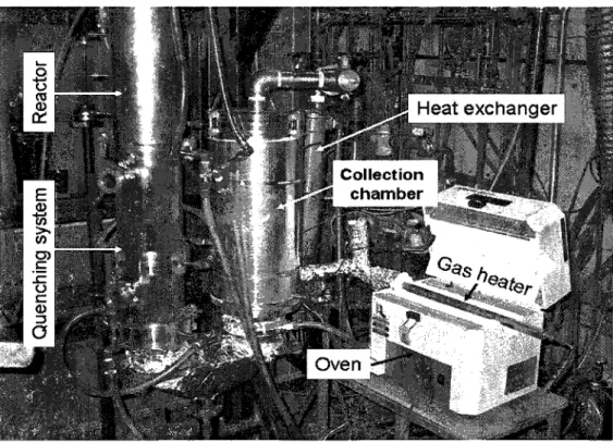
The collection chamber and connector tube between quenching system and collection section (elbow tube) shown in figure 3.6 are covered by ceramic wool. A gas heater placed in the oven is used to preheat the inlet gases (i.e. air and oxygen). The temperature of inlet gas is measured by a K-type thermocouple and controlled by the oven.During in situ purification the process temperature in the collection chamber exceeds 2500C; therefore a heat exchanger shown in figure 3.6 should be applied to cool down the exhausted gases before going to the vacuum pump.
P
u
HH¦
¦ f»»» ?/li
¦ aI
O ra Heat exchanaer ? I ÛÎ 1 ? Collection chamber ? IB* ? ¦ to ? ¡Égal IB ¦ s» IG «&» ¡? ? H<^*w
?Hic
¦? m ? ¦ Oven ¦ WEM @mm
¦a-'is s MV%hJ3.3 Chemicals
For the carbon source, carbon black powder (Raven 860, Columbian Inc.) was chosen, and ternary mixtures of nickel (Ni, 99.5 %, < ?µp?), cobalt (Co, 99.8 %, < 2µ??), and yttrium oxide (Y2O3, 99.9 %, ~5µp?) were employed as metal catalysts in the following proportions: N1/C0/Y2O3 - 0.6/0.6/0.4 at.% ( 98.4 at% of carbon black). These feedstock materials were introduced axially through a water-cooled probe located at the center of the plasma torch (TEKNA PL-50) to produce SWCNT soot in a vaporization-quenching system. Some physical
properties and the company of each chemical are summarized in table 3.2.
TABLE 3.2 FEEDSTOCKS OF SWCNT PRODUCTION
Carbon powder Density
(g/cm3)
Surface Area(m2/g)
Particle Size (nm) CompanyRaven 860 ultra Not provided 48 39 Colombian
Catalyst Density
(g/cm3)
Surface Area
(m2/g)
Particle Size Company
Co 8.90 < ?µp? Cerac
Ni 8.90 <2µp? Sigma-Aldrich
Y2O3 4.84 ~5µp? Hermann C. Starck
To oxidize SWCNT soot thermally in order to get rid of amorphous carbon, two types of gas were injected in to the filtration system in turn.
First, dry air (dew point of < -1 1°C) was used at a flow rate of 38.54 SLPM providing 5 vol% of
oxygen in the collection chamber. In next attempt, pure oxygen was used in three different flow
rates 8.44 SLPM, 12.56 SLPM and 17.22 SLMP providing 5, 7.5 and 10 vol% of the total gases inside the collection chamber respectively.3.4 Characterization techniques
The most common analytical techniques used to characterize single-walled carbon nanotubes are transmission electron microscopy (TEM), high resolution scanning electron microscopy (HRSEM), thermo-gravimetric analysis (TGA) and Raman spectroscopy. TEM and HRSEM
images are useful to investigate interior morphology and exterior morphology of the SWCNTs
respectively. TGA and Raman spectroscopy can be used to monitor the purity of SWCNT in the
soot quantitatively and qualitatively respectively.
3.4.1 Raman spectroscopy
Raman spectroscopy is one of the most powerful tools for characterization of carbon nanotubes.
A fast and non-destructive analysis is possible with a straightforward sample preparation method. The interesting thing is that all allotropie forms of carbon are active in Ramanspectroscopy [Belin et a¿, 2005]. These comprise carbon nanotubes, amorphous carbon, partial
amorphous and crystalline carbon (glassy carbon, diamond like carbon), micro-, nano- or
poly-crystalline carbon (diamond, hard carbon and graphite), poly-crystalline carbon (diamond and
graphite) and fullerenes. Carbon nanotubes and crystalline carbon contribute sharp Raman lines
that make them obviously distinguishable from the other carbon allotropes[Sivaram é>/ a/, 2004].
The most characteristic features are summarized, shown in figure 3.7, as follows:
(i) A low-frequency peak < 200 cm"1 (or bunch of peaks for polydisperse samples when
resonating conditions are met) characteristic of the SWCNTs assigned to the AIg "breathing"
mode of the tubes, whose frequency depends essentially on the diameter of the tube (RBM: radial
breathing mode).Radial breathing mode is a characteristic phonon mode of single-walled carbon nanotubes in
Raman spectroscopy. The frequency of radial vibration of a nanotube approximated by a
homogeneous cylinder is linear with the inverse tube diameter (1/d). RBM causes a periodic
increase and decrease in diameter of the tubes and the relation between this period and the tubeûfaw=4+^
(3i>
The offset of A2 was originally introduced to account for additional external forces such as interactions with substrate or neighbouring tubes in a bundle.
This equation is often used to calculate the tube diameters and determine the diameter distribution in a nanotube sample from Raman scattering. This method needs a knowledge of
coefficients A l and A 2 . It should be mentioned here that the experimental and theoretical values
of A1 reported in many literature vary between 220 and 260 cm"'nm and A2 varies between
0 and 20 cm"1 . Bachilo et a¿ (2002) reported 223.5 cm"'nm and 12.5 cm-1 as values for A1
and A 2 respectively.
, .
.
223.5cm-1 «m
a. {nm) =
r
n ??
ü)RBM -12.5cm"1
(3·2)
d, : diameter of SWCN tubes
(Orem '¦ Wave number (cm-1 )
TEM and SEM images of SWCNTs synthesized by induction thermal plasma indicate many individual tubes. No evidence of big bundles of tubes was observed during SEM and TEM
analysis. According to these observations the coefficient related to external forces in equation 3.2
can be negligible. Therefore carbon nanotube diameter calculation may be carried out by using a
simplified equitation as follows:. .
.
223.5cm~]nm
dt {nm) =
Cu(3 3)
WRBM
(ii) A large structure (1340 cm-1) assigned to residual ill-organized graphite, the so-called
(iii) High-frequency features (between 1500 and 1600 cm-1 ) called G-band also characteristic of
nanotubes, correspond to a splitting of the E2g stretching mode of graphite. This bunch could be superimposed with the G-line of residual graphite
(iv) A second order mode observed between 2450 and 2650 cm"1 is assigned to the first
overtone of the D mode and often called G '-band.
(v) A combination mode of the D and G modes between 2775 and 2950 cm ' . [Beline et at,
2005] «o G-band \ y RBM D-band G -band Figure 3.7
200 4OO éOO SOO IOOO I20O 14OO I «SOU I8O0 2000 22OO 2400 26OO 2BOO 30001
Raman Shift (cnî'ji
Raman spectrum showing the most characteristic features of CNTs: radial
breathing mode (RBM), the D-band, G-band and G'-band. Second order modes
are also observed, [from Belin et «/,2005]
The position, width and relative intensity of the peaks differ with carbon allotropes [Sivaram et
at, 2004]. The low-intensity dispersive D-band is associated with disordered, sp3-hybridized
carbon present as impurities and SWNCT defects. For this reason, the ratio of the amplitudes of
the G-band and the D-band has been used as a measure of the purity of as-produced SWCNT soot and to evaluate the efficiency of purification. The majority of purity evaluations using Raman measurements of SWCNT materials have made use of solid-phase SWCNT samples inthe form of powders, thin films, or individual SWCNTs on substrates [Itkis et at, 2005]
a) Operating conditions of Raman analysis
In this work Raman analysis was performed with the following conditions: 1. Excitation wavelength: 632.8 nm He-Ne laser
2. Laser power: approximately 2 mW
3. Integration times for spectral collection: 10 seconds per acquisition
4. Raman shift: 32-1880 cm-1
b) Data Processing
1. Low frequency. 32-799 cm"1 ( baseline correction: 500 cm-1 )
2. Medium frequency: 820-1249 cm"1
3. High frequency: 1250-1880 cm"1
3.4.2 Thermo-gravimetric analysis (TGA)
Although SEM and TEM methods are usually used to evaluate the purity of SWCNTs, the use of these methods for quantitative evaluation of the purity of bulk samples is highly problematic. Itkis et at (2003) estimated that the amount of material that can be seen and analyzed within
one SEM frame is less than 10 "12 g.
"It is virtually impossible to homogenize a 10-g batch of as-prepared SWCNT soot to a
level of 10~12 g, which is what would be required to make 1 SEM frame or even 10
frames sufficiently representative to allow definitive conclusions about the purity of the bulk sample to be drawn. Even under the assumption of representative SEM images, there is no algorithm that has been described in the literature that allows the quantitative evaluation ofSWCNT s purity from SEM images. ' ' [Itkis et at, 2003]Thermo-gravimetric analysis involves heating a sample in an inert or oxidizing atmosphere such
as Air or CO 2 and measuring the weight. The weight change over specific temperature ranges
provides indications of the composition of the sample and thermal stability. It can be used tomonitor changes in weight in relation to changes in temperature of a sample in the desired
atmosphere.Drawing weight versus temperature gives a TGA curve. In the case of carbon nanotube samples,
as the temperature increases the weight of sample in an oxidizing environment such as air
decreases, except over a narrow temperature range (~200°C-250°C) where a slight weight increase is observed due to the oxidation of Ni and Co metals [Li e¿ a¿, 2005] . A derivativeweight loss curve can be used to precisely indentify multi step weight loss events occurring in an
oxidizing atmosphere (figure 3.8).T h ermo -gravi metri c Analysis
120 100 f 80 ?
S 60
I
20 0 ? 16wt%...t..
t 1-°·? _
-0.2 > 0 f a —? 1 1 1 1 1 1 100 200 300 40D 500 600 700 800 9DO 0.2 Te m pelature0 CFigure 3.8 A typical TGA/DTG profile of as-produced SWCNT soot synthesized by induction thermal plasma process
Several stepwise weight losses can be clearly identified from figure 3.8. The derivative weight
loss curve is specified by a dashed line. Each peak in the DTG curve is in relation to the burning
of an ätiotrope of carbon. An increment in temperature causes a decrease in the sample weight up
to 7000C. The residual mass observed in the TGA trace corresponds to fully oxidized catalyst metals and is consistent with the initial concentration of metals in the raw powder mixture (16 wt%).TG analysis is a useful method to calculate the amount of metallic catalysts in SWCNT products
as they are more resistant than the allotropes of carbon in an oxidizing atmosphere with
temperatures higher than 7000C. Because TGA is inherently quantitative, it is an extremely
powerful thermal technique to quantify the concentration of the different carbon structures and
especially SWCNTs produced in the synthesis process. However, correlating these individual oxidation events in TGA/DTG profiles to specific sample components of SWCNTs samples canbe very challenging. In a DTG curve, each peak relates to one type of carbon allotrope as they
don't have same burning temperature in the presence of oxygen. Calculation of the area under the DTG curve of each peak gives the weight percentage of each material in the sample. Therefore TG analysis can be a good method to evaluate the purity of SWCNTs quantitatively. Using this procedure requires the burning temperature of each species in the sample to determine the weight percent of SWCNTs as well as carbonaceous impurities.Thermo-gravimetric measurements were made on a TA Instruments TGA 2050 Seteram thermal analyzer and performed with conditions listed below:
• Ramp 10°C/min from room temperature to 9000C • Gas: Air
• Flow rate: 40 seem in the sample oven
• Initial sample weight: approximately 10 to 20 mg
3.4.3 High resolution scanning electron microscopy (HRSEM)
The diameter of single-walled carbon nanotubes fall in the nanometer range (1-3 nm).
Synthesized SWCNT lengths can reach up to several microns. At these scales, HRSEM is well
suited for the imaging of SWCNTs. A Field Emission Scanning Electron Microscope (SEM,
Hitachi, S4700) was used to characterize the morphology of SWCNTs and impurities produced in the plasma process."The SEM technique has been extensively used to monitor the efficiency of the bulk
scale production of SWNCTs by a variety of synthetic techniques, and it has
traditionally been the most popular tool to evaluate the quality of as-prepared
SWCNT soot [Itkis et a¿, 2005] . ' 'The operating parameters used during the SEM analysis were accelerating voltage of 1.2 kV and
a working distance of 2.5 mm.Under these conditions, it was possible to analyze the nanometric details of the carbon nanotubes
and from a clear image of the sample at magnification of 100000X or even more (up to
200000X).
3.4.4 Transmission Electron Microscopy (TEM)
Although high resolution scanning electron microscopy can reveal important external features of
the sample, the TEM technique allows determination of the internal structure of the sample. This
technique is one of the most powerful microscopic techniques for SWCNTs and carbon
nanostructure characterization because of the ultra high magnifications that can be reached. Forinstance, using TEM allows us to characterize morphologically and structurally SWCNTs better.
To investigate whether carbon nanotubes have been damaged during in situ purification or not,
the TEM technique can be a good candidate because of the reasons discussed above.
In order to identify the major impurities in the as-produced SWCNTs and to estimate changes in
the SWNT samples through the purification process some properties of the samples were
analyzed by transmission electron microscopy (TEM, Hitachi H750).
3.5 Sample collection and preparation procedure
3.5.1 Sample collection method
Characterization of produced material with different techniques such as TEM, HRSEM, TGA,
and Raman usually needs a few milligram of sample. The collection chamber has a length of
50 cm and filter tubes have a length of 45 cm. The purified materials containing SWCNTs are
deposited on the filter tubes making a sheet like soot. Each sheet with a length of 45 cm and a
width of 15.7 cm has an area of 706.5 cm2. For sample gathering two assumptions were made as
1- First assumption that should be considered is that all three filter tubes are in the same
position (figure 3.9); therefore the sample for characterization can be collected from each
tube without considering where it is located in the chamber.2- Second assumption is that the temperature gradient exists only in the axial direction. This
assumption allows us to collect the samples from each side of the tube, whether it is
closer to the center or the wall of the collection chamber.
The temperature measurement along the collection chamber indicated a very high temperature
gradient during SWCNTs synthesis process. Figure 3.10 indicates the temperature profile along
the collection chamber measured by several K-type thermocouples installed vertically to the axis of the collection chamber. The exothermic reaction between oxygen and allotropes of carbonstrongly depends on temperature. At the same concentration of oxygen, temperature has a great
role on the carbon-oxygen reaction.V) Mn
1
¦¦i ¦ li Filter Tubes Collection ? 1 r chamber i / I w ? \Figure 3.9
The 3-D scheme of collection chamber and filter tubes used to collect SWCNTs
synthesized by induction thermal plasma from exhausted gases.
Temperature Profile
600 -,0 500 -
m_
£ 400 -
^^f^-1 300 -
^^r^_
E 200 "
—"^--*
& *- 100 0 -I 1 1 1 1 1 T3 T4 T5 T6 T7 Thermocouple PositionsFigure 3.10
Temperature profile along the collection chamber during SWCNTs synthesis
process
It can be seen easily from figure 3.10 that the temperature inside the collection chamber
![Figure 2. 1 Schematic diagram of the apparatus used for thermal annealing in the air [from Moon et at, 2001]](https://thumb-eu.123doks.com/thumbv2/123doknet/3373087.97626/26.898.209.690.700.981/figure-schematic-diagram-apparatus-used-thermal-annealing-moon.webp)