Département de génie chimique et de génie biotechnologique
ÉTUDE DE LA FORMATION DE BOUES DANS LA
CELLULE HALL-HÉROULT
Thèse de doctorat
Spécialité : génie chimique
Mojtaba FALLAH FINI
Sherbrooke (Québec) Canada
7 mai 2020
Gervais SOUCY
. DirecteurMartin DÉSILETS
. CodirecteurDuygu KOCAEFE
. Évaluatrice externeVéronique DASSYLVA-RAYMOND
. Évaluatrice externeJocelyn VEILLEUX
. Évaluateurdans l’économie du Québec. Un facteur qui peut augmenter la consommation d'énergie correspondante est la formation de dépôts résistifs (des boues) à la surface de la cathode. Par conséquent, l'objectif de cette thèse est de clarifier davantage la nature complexe de la formation de boues dans le procédé Hall-Héroult, en tant que le procédé principal de production d'aluminium.
Les objectifs de recherche sont:
a) étudier l’effet possible de la nuance de cathode sur la formation ou la dissolution des boues;
b) déterminer l'importance relative de trois paramètres opérationnels, à savoir la température d’opération, le ratio de cryolite (CR) ainsi que la nuance de cathode; c) étudier de façon expérimentale des boues induites chimiquement (c'est-à-dire
précipitation des espèces cryolitiques dues au changement de la chimie du bain comme la consommation d'alumine ou la polarisation de concentration de sodium).
La méthodologie expérimentale comporte une configuration expérimentale à l'échelle du banc d’essai, cinq nuances cathodiques différentes, une conception de plan expérimental factoriel complet ayant trois variables et deux niveaux pour chaque paramètre, à savoir la température d’opération (940 et 960 ° C), le ratio de cryolite (2,2 et 3,8) et deux nuances cathodiques. Les résultats de cette recherche sont:
i. une combinaison de porosité ouverte et de perméabilité à l'air des cathodes affecte l'épaisseur des couches de carbure d'aluminium;
ii. parmi plusieurs propriétés, la conductivité thermique et la porosité ouverte des cathodes affectent la tendance à la formation de boues en raison de la perte de chaleur au fond de la cellule et des phénomènes interfaciaux;
iii. l'influence significative de la température d’opération par rapport au ratio de cryolite et à la nuance de cathode;
iv. la précipitation des espèces cryolitiques solides est accélérée grâce à la polarisation de concentration plus élevée et le taux d'épuisement de l'aluminium plus rapide;
v. le temps de réalimentation des boues est plus élevé pour les cathodes à porosités ouvertes plus élevées en raison de l'interaction des boues, avec des couches de carbure plus épaisses et des espèces carbonées au fond de la cellule.
Mots-clés : Procédé Hall-Héroult, aluminium, électrolyse, thermodynamique, cathode, cryolite,
major role in the Québec’s economy. One factor that can increase the corresponding energy consumption is the formation of resistive deposits, such as sludge, on the surface of the cathode lining. The aim of this PhD thesis is to shed some light on the complex nature of sludge formation in Hall-Héroult process, as the main process for production of aluminum.
The research objectives are:
a) to study the possible effect of the cathode grade on sludge formation or dissolution; b) to evaluate the relative importance of three operational parameters, namely the
operational temperature, the cryolite ratio (CR) as well as the cathode grade;
c) to carry out an experimental investigation of chemically induced sludge (i.e. precipitation of cryolitic species due to change of bath chemistry such as alumina consumption or sodium concentration polarization).
The experimental methodologie includes an experimental bench scale set-up, five different graphitized cathode grades, a full factorial experimental plan design having three variables and two levels for each parameter, namely the operational temperature (940 & 960 °C), the cryolite ratio (2.2 and 3.8), and two cathode grades.
The results of this research are:
i. a combination of open porosity and air permeability of the cathodes affects the thickness of deposited aluminum carbide layers;
ii. among several properties, thermal conductivity and open porosity of the cathodes affect the sludge formation tendency of the cathode lining due to heat loss at the bottom of the cell and interfacial phenomena;
iii. there is overwhelming influence of operational temperature versus the cryolite ratio and cathode grade;
iv. the precipitation of solid cryolitic species is expedited thanks to a higher concentration polarization and a faster aluminum depletion rate;
v. the back-feeding time of sludge layers is higher in cathodes with higher open porosities because of the interaction of the sludge with thicker carbide layers and carbonaceous species at the bottom of the cell.
Keywords: Hall-Héroult process, aluminum, electrolysis, thermodynamics, cathode, cryolite,
supporté tout le temps même avec leur horaire surchargé. Je vous en serai perpétuellement reconnaissant.
En deuxième lieu force est de reconnaître a) les apports techniques d’André Bilodeau et Serge Gagnon en laboratoire, b) les supports analytiques des membres de la plateforme de recherche et d'analyse des matériaux (PRAM), à savoir Carl St-louis, Sonia Blais, Stéphane Gutierrez et Charles Bertrand, c) les apports techniques et théoriques des coauteurs des articles, soit Patrick Pelletier et Didier Lombard de Rio-Tinto ainsi que Loig Rivoaland et Regis Paulus de Carbone Savoie, et enfin et surtout d) les supports analytiques et émotionnels de Olivier Drevelle. Il faut également apprécier mes collègues et mes pairs Jean-René Landry, Martin Brassard, Colin Dessemond et François Allard qui m’ont aidé durant mes études.
Ensuite, force est de constater que je n’aurais jamais pu accomplir tout cela sans l’aide de ma famille et mes copains. D’abord, je suis éternellement redevable à ma sœur professeure Saeideh Fallah-Fini. Quoique soit les succès que j’ai obtenus au cours de ma vie, je te les dois.
De surcroît, il faut mentionner ma chère amie Faranak et son copain Bijan qui étaient à mes côtés durant les temps difficiles. Je souhaite aussi montrer toute ma gratitude à mon amie Gabriela, son époux Thierry et leur chinchilla Tigars. Enfin, je ne peux pas oublier mes amis qui étaient toujours bienveillants envers moi, à savoir Azin Aghdaei, Massoud Karami, Tony Kunnari, Rejean Loiselle, Steeve Turmel, Konstantin Ntokas, Alexandre Marquis, Pierre Bigonesse, Mairy D-Mendoza, Hamid Hassanisaber et tous ceux que j’aurais pu oublier. Finalement, j’aimerais remercier toutes mes professeures de langue française, surtout Vicky Poirier, grâce à qui j’ai obtenu le diplôme d'études en français langue seconde et j’ai appris assez de subtilités de la langue française de manière à oser écrire et présenter ma thèse en français.
i
TABLE DE MATIÈRES
LISTE DES FIGURES ... v
LISTE DES TABLEAUX ... ix
LEXIQUE DES RÔLES DES AUTEURS ... xi
LISTE DES ACRONYMES ... xiii
CHAPITRE 1 INTRODUCTION ... 1
1.1 Mise en contexte et problématique ... 1
1.1.1 Production d’aluminium primaire ... 1
1.1.2 Procédé Hall-Héroult ... 1
1.1.3 Nuances de blocs cathodiques ... 2
1.1.4 Problématique ... 3
1.2 Questions de recherche ... 4
1.3 Objectifs du projet de recherche ... 4
1.4 Contributions originales ... 5
1.4.1 Revue de la littérature sur la formation de boue et ses désavantages ... 5
1.4.2 Impact de la nuance de cathode sur la dissolution de boue ... 5
1.4.3 Surchauffe comme paramètre clé de la formation de boue ... 6
1.4.4 Précipitation des espèces cryolitiques et ses interactions avec de la boue ... 6
1.5 Plan du document ... 7
CHAPITRE 2 ÉTAT DE L’ART ... 9
2.1 Avant-propos... 9
2.2 Sludge Formation in Hall-Héroult Cells: Drawbacks and Significant Parameters ... 11
2.2.1 Abstract ... 11
2.2.2 Introduction ... 11
2.2.3 Sludge formation and its drawbacks ... 13
2.2.4 Influence of cathode carbon materials ... 23
2.2.5 Fluid dynamics ... 25
2.2.6 Interfacial phenomena ... 27
2.2.7 Temperature ... 30
2.2.8 Bath chemistry ... 31
2.2.9 Physicochemical characteristics of alumina ... 33
ii
2.2.11 Conclusions ... 42
CHAPITRE 3 MÉTHODOLOGIE... 45
3.1 Description du montage expérimental ... 45
3.2 Plans d’expériences ... 47
3.2.1 L’impact de la nuance de bloc cathodique ... 47
3.2.2 L’impact des paramètres d’opération ... 48
3.3 Autopsies et méthodes d’analyse ... 48
3.3.1 Microscopie optique ... 51
3.3.2 Diffractométrie de rayons X (DRX), Fluorescence des rayons X (FRX)... 51
3.3.3 Microscopie électronique à balayage et spectroscopie par dispersion d’énergie ... 52
3.3.4 Analyse élémentaire de l’oxygène ... 52
3.4 Calculs thermodynamiques ... 52
CHAPITRE 4 IMPACT DE LA NUANCE DE CATHODE SUR LA FORMATION DE CARBURES ... 55
4.1 Avant-propos ... 55
4.2 Laboratory Study of the Impact of the Cathode Grade on the Formation of Deposits on the Cathode Surface in Hall-Héroult Cells ... 59
4.2.1 Abstract ... 59 4.2.2 Introduction ... 59 4.2.3 Methodology ... 61 4.2.4 Results ... 62 4.2.5 Discussion ... 65 4.2.6 Conclusions ... 66
CHAPITRE 5 IMPACT DE LA NUANCE DE CATHODE SUR LA FORMATION DE BOUES ... 69
5.1 Avant-propos ... 69
5.2 Experimental Investigation of the Impact of the Cathode Grade on Sludge Formation at the Cathode Block-Aluminum Interface of Hall-Héroult Cells ... 73
5.2.1 Abstract ... 73 5.2.2 Introduction ... 73 5.2.3 Methodology ... 76 5.2.4 Results ... 79 5.2.5 Discussion ... 88 5.2.6 Conclusions ... 93
iii
BOUES ... 95
6.1 Avant-propos... 95
6.2 Chemically Induced Sludge Formation in Hall-Héroult Process ... 97
6.2.1 Abstract ... 97
6.2.2 Introduction ... 97
6.2.3 Materials and methods ... 98
6.2.4 Results ... 103
6.2.5 Discussion ... 107
6.2.6 Conclusions ... 115
CHAPITRE 7 CONCLUSION ... 117
7.1 Sommaire ... 117
7.1.1 Importance des propriétés des blocs cathodiques ... 117
7.1.2 Importance relative des paramètres d’opération ... 118
7.1.3 Précipitation des espèces cryolitiques ... 119
7.2 Contributions... 120
7.2.1 Revue sur la formation de boue concernant le procédé Hall-Héroult ... 120
7.2.2 Nuance de cathode et formation/dissolution de boues ... 120
7.2.3 Il s’agit de surchauffe et de cinétique ... 120
7.3 Travaux à l’avenir ... 121
ANNEXE A…….. ... 123
A.1 Exposé de conférence ICSOBA 2017 ... 123
A.1.1 Avant-propos... 123
A.1.2 Sludge Formation in Hall-Héroult Process: An Existing Problem ... 125
v
LISTE DES FIGURES
Figure 1-1. Cellule d’électrolyse d’aluminium; a) caisson en acier, b) isolation, c) barre collectrice, d) pâte de brasque, e) bloc de carbure de silicium, f) aluminium, g) bain, h) talus et pied de talus, i) croûte d’anode, j) matériau de recouvrement d’anode, k) capot, l) tige d’anode, m) système d’alimentation d’alumine ... 2 Figure 2-1. DC electrical energy consumption and current efficiency in Hall-Héroult process
[Welch et Kinery, 2000; Tabereaux et Peterson, 2014; International-Aluminium-Institute, 2019] ... 12 Figure 2-2. Typical loci of common deposits within a typical aluminum electrolysis cell ... 12 Figure 2-3. The horizontal and vertical arrows show the formation of solid cryolitic species
because of depletion of alumina and sodium concentration polarization at the bath-metal interface respectively. ... 14 Figure 2-4. Interfacial movements within the aluminum electrolysis cells [Utigard et Toguri,
1991] “Copyright 1991 by The Minerals, Metals & Materials Society. Used with permission.” ... 28 Figure 2-5. The schematic influence of temperature and bath acidity on the operation of the
cells; the bath includes 0.5 wt% MgF2, 3 wt% alumina and 5 wt% CaF2. [Taylor, 1997]
... 31 Figure 2-6. Comparison of bath temperature change versus time for two feeding strategies; The
solid lines and dashed lines correspond to point feeding and center working respectively [Walker et coll., 1995]. “Copyright 1995 by The Minerals, Metals & Materials Society. Used with permission.” ... 38 Figure 2-7. Dissolution behavior of one-stage well dispersed (dashed line) and two-stage
agglomerated alumina particles (solid line) [Jain et coll., 1983b]. “Copyright 1983 by The Minerals, Metals & Materials Society. Used with permission.” ... 39 Figure 2-8. Effect of dumping height (h) on the dissolution behavior of alumina; ● (h=2 cm), ▲
(h=10 cm), ■ (h=60 cm) [Bagshaw et coll., 1985]. “Copyright 1985 by The Minerals, Metals & Materials Society. Used with permission.” ... 40 Figure 2-9. The temperature drop when the bath was fed with plugged holes (solid line) and
open holes (dashed line) [Kobbeltvedt et coll., 1996]. “Copyright 1996 by The Minerals, Metals & Materials Society. Used with permission.” ... 41 Figure 3-1. Banc d’essai pour l’électrolyse d’aluminium à haute température ... 45 Figure 3-2. Dimensions et composantes d’une cellule expérimentale; vue de haut (a) et vue de
côté (b); 1 : bloc cathodique, 2 : plaques de SiC/Al2O3, 3 : anode, 4 : bain, 5 : aluminium,
6: barre collectrice; toutes les dimensions sont en millimètres [Landry et coll., 2018].46 Figure 3-3. Un bloc cathodique recouvert de feutre de carbone et de plaques en InconelTM .... 46
Figure 3-4. Schéma du montage expérimental; 1 : four, 2 : isolation en alumine, 3 : porte-creuset en InconelTM, 4 : tiges de cathode, 5 : tiges d’anode, 6 : bain, 7: aluminium, 8 : bloc
vi
silicium, 12 : carreau de carbure de silicium, 13 : barre collectrice, 14 : anode, 15 : point d’échantillonnage, 16 : thermocouple ... 47 Figure 3-5. Première façon de coupage (lignes pointillées rouges) pour étudier l’impact de la
nuance de bloc cathodique afin d’observer l’interface carbone-aluminium a) au microscope optique et b) au microscope électronique. [Landry et coll., 2019] ... 50 Figure 3-6. Deuxième façon de coupage (lignes pointillées rouges) pour étudier l’impact des
paramètres d’opération; à gauche : vue de côté et à droite : vue de haut; les plaques de carbure de silicium sont illustrées en noir. ... 50 Figure 3-7. Mesure des dimensions d’une boue typique; toutes les dimensions sont en mm. .. 50 Figure 3-8. Configuration du diffractomètre et du détecteur XRF; adaptée de Feret [2008].... 52 Figure 4-1. Sizing of experimental Hall-Héroult cells for this study, top view (a) and side view
(b). All dimensions are in millimeters. 1: carbon crucible, 2: alumina plates, 3: anode, 4: bath, 5: aluminum pad ... 61 Figure 4-2. Scanning electron microscopy of the carbon-aluminum interface of experimental
cell E (impregnated graphite). The position of the aluminum carbide layer is shown by the bracket symbol. ... 63 Figure 4-3. Sludge profiles for graphitized grade A (a), impregnated graphite grade E (b) ... 64 Figure 4-4. Thickness of the aluminum carbide layer at the carbon-aluminum interface of the
five experimental cells (triangles: graphitized blocks; circle: impregnated graphite). . 65 Figure 5-1. Deposits at the carbon-metal interface of Hall-Héroult cells ... 74 Figure 5-2. Sizing of experimental Hall-Héroult cells for this study, top view (a) and side view
(b). All dimensions are in millimeters (mm). 1: carbon crucible, 2: alumina plates, 3: anode, 4: bath, 5: aluminum, 6: bus bar. TW and TB refer respectively to the positions of
the thermocouples in the sidewall and in the bath ... 77 Figure 5-3. Positions of cuts for deposit observation (red dashed lines); a) cuts of the cell and
cathode surface for microscopic sludge observations; b) cutting for SEM observations of the carbon-aluminum interface ... 78 Figure 5-4. Temperature profile of the bath for the five experimental grades during electrolysis ... 80 Figure 5-5. Microscopic observations of the carbon-aluminum interface profile in the center of
the cell for the five cathode grades; grade A (a), grade B (b), grade C (c), grade D (d) and grade E (e)... 81 Figure 5-6. Characterization summary of all experiments; the red markers are the average values
by grade with the standard deviation; CR of ledge toe (a), total alumina mass percentage of ledge toe (b), CR of central sludge (c) and total alumina mass percentage of central sludge (d) ... 83 Figure 5-7. Transversal cut of a typical experimental cell and the average alumina mass
percentage and CR of the indicated zones; the yellow arrows indicate the typical region where the maximum erosion of alumina plates occurs. The region circled in red indicates that it is supersaturated in alumina ... 83
vii
the yellow filled circle and X mark indicate respectively the initial condition of electrolysis and the composition of the bulk bath at the end of the run. ... 85 Figure 5-9. Average voltage by cathode grade ... 87 Figure 5-10. SEM-EDS observation of the indicated zone of the carbon-aluminum interface for
grade C ... 87 Figure 5-11. Average cooling rate per cathode grade and average thermal conductivity of the
block: average conductivity was obtained by averaging the horizontal and vertical conductivities ... 89 Figure 5-12. a) Bath film connecting the bottom bath layer and the bulk (CR – alumina wt%)
for one run with cathode grade A, b) film movement induced by sodium losses in cathode block ... 91 Figure 6-1. Experimental cell components and dimensions; top view (a) and side view (b). All
dimensions are in millimeters (mm). 1: carbon crucible, 2: silicon carbide plates, 3: anode, 4: bath, 5: aluminum, 6: collector bar, 7: carbon felt, 8: InconelTM plate. ... 100 Figure 6-2. Schematic of the experimental set-up; 1: furnace, 2: alumina insulation, 3:
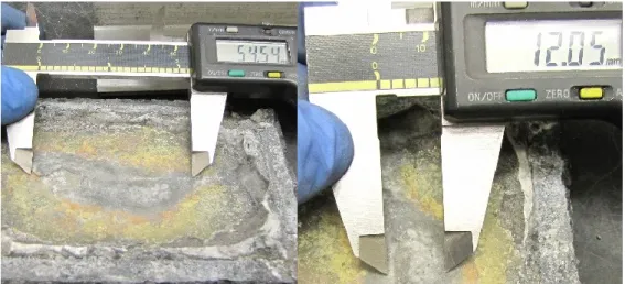
cylindrical InconelTM container, 4: cathodic rod, 5: anodic rods, 6: bath, 7: aluminum metal pad, 8: cathodic block, 9: InconelTM plate, 10: carbon felt layer, 11: silicon carbide plates, 12: silicon carbide tile, 13: collector bar, 14: anode, 15: cold finger entrance, 16: thermocouple ... 101 Figure 6-3. The cutting positions during the autopsy procedure; ... 102 Figure 6-4. Measurement of dimensions of a typical sludge; all the dimensions are in mm. . 103 Figure 6-5. The influence of each parameter on the volume of the sludge (mm3×10-2); a) average
operational temperature (ºC); b) initial CR; c) cathode grade ... 104 Figure 6-6. Triplicate of a test at average operational temperature of 960 °C, initial CR of 2.2
(Group 1); solid lines are the three replicas and the dotted line shows the average value. ... 105 Figure 6-7. Triplicate of a test at average operational temperature of 960 °C, initial CR of 2.2
(Group 2); solid lines are the three replicas and the dotted line shows the average value. ... 106 Figure 6-8. Depletion of alumina for two sets of experiments; Group 1 (■, ▲, ●); Group 2 (○, ♦);
the dashed lines show the average values for the replicas; the solid lines show the absolute value of alumina depletion rate. ... 106 Figure 6-9. Influence of superheat level on the extent of sludge formation; ● shows a cell having
superheat level of 9.5°C; ■ shows a cell having a superheat level of 2.5°C; ○ shows the liquidus temperature of the system being 955.5°C; the dashed areas show the precipitation regions. ... 107 Figure 6-10. A thermodynamic system having CR = 2.2 and 5 wt% of CaF2; initial point (■),
bulk of the bath at the end of the electrolysis (♦) and sludge (▲); The solid line and dashed line show different liquidus lines at initial point and end of the electrolysis,
viii
respectively. A) positive initial superheat level, B) precipitation region, C) negative final superheat level, D) negative superheat level of the sludge ... 108 Figure 6-11. Electrical conductivity of the solid solution (■), specific heat capacity (●) and
thermal conductivity of the liquid fraction at three temperatures for a typical bath containing 6.2 wt% of CaF2, 2.9 wt% of Al2O3 and a CR = 2.9; the data are calculated
using FactSage software. ... 110 Figure 6-12. Comparison of average operational temperatures for tests in Group 1 (solid line)
and tests in Group 2 (dashed line) ... 111 Figure 6-13. Comparison of sludge formation for two tests at average operational temperature
of 960 °C and an initial CR of 2.2; a) Group 1; b) Group 2 ... 112 Figure 7-1. Effet de fendage à cause de la production locale d’aluminium en dessous d’une
couche de boue; l’aluminium produit se comporte comme une cale (coin). Les flèches jaunes illustrent la force déployée en raison de la formation et de l'accumulation d’aluminium, ce qui enlève partiellement la boue... 118
Figure A- 1. The schematic influence of temperature and bath acidity on operation of the cells; adapted from Taylor et Welch [2004] and Allard et coll. [2015]. ... 130
ix
LISTE DES TABLEAUX
Table 2-1. Typical composition of different bottom solid phases found in industrial cells [Allard
et coll., 2015] ... 15
Table 2-2. Observations on central deposits from industrial electrolysis cells ... 17
Table 2-3. Experimental laboratory scale investigations of central deposits ... 19
Table 2-4. Influence of additives on physicochemical properties of the bath; ↑ increase, ↓ decrease [Grjotheim et Kvande, 1993; Habashi, 2003] ... 32
Table 2-5. Comparison between different feeding systems [Grjotheim et coll., 1989]. “Copyright 1989 by The Minerals, Metals & Materials Society. Used with permission.” ... 37
Tableau 3-1. Propriétés des blocs cathodiques ... 48
Tableau 3-2. Conditions expérimentales d’après le plan factoriel complet ... 49
Table 4-1. Cathode block properties at room temperature (*: horizontal; **: vertical) ... 61
Table 4-2. Average aluminum carbide layer thickness is ± 4 μm. The average data for two tests of each grade is displayed. ... 63
Table 4-3. CR, total alumina content and height of ledge toe and central sludge deposits from XRD analysis ... 64
Table 5-1. Cathode block properties at room temperature (*: horizontal; **: vertical) ... 76
Table 5-2. Total alumina content (from Rietveld refinement) and cryolite ratio of central and ledge toe sampled in cells from Figure 5-5 ... 82
Table 5-3. Qualitative observations of carbon-aluminum interface for each cathode grade ... 86
Table 6-1. Chemical composition (wt%), CR, initial liquidus temperature (Tliq.-in. ºC) and final liquidus temperature (Tliq.-fin. ºC) of the two synthetic baths ... 98
Table 6-2. Properties of the cathodic blocks at room temperature ... 99
Table 6-3. Experimental plan ... 101
xi
LEXIQUE DES RÔLES DES AUTEURS
Conceptualisation : formulation ou évolution d'objectifs et de buts de recherche.
Analyse formelle : application des techniques statistiques, mathématiques, informatiques ou
d’autres techniques formelles pour analyser ou synthétiser les données.
Acquisition de financement : acquisition du soutien financier du projet.
Investigation : réalisation des expériences ou la collection de données / preuves. Méthodologie : développement ou conception de méthodologie.
Administration de projet : gestion et coordination de la planification et de l'exécution des
activités de recherche.
Ressources : fourniture de réactifs, de matériel, d'échantillons de laboratoire, d'instruments, de
ressources informatiques ou d'autres outils d'analyse.
Supervision : supervision de la planification et l'exécution des activités de recherche.
Validation : vérification de la réplication / reproductibilité globale des résultats / expériences
et autres résultats de recherche.
Visualisation : préparation, création et / ou présentation de l'œuvre publiée. Rédaction - premier brouillon : la rédaction de l'ébauche initiale.
Rédaction - revue et révision : révision critique, commentaire ou révision.
1 Brand, A., Allen, L., Altman, M., Hlava, M. & Scott, J. 2015. Beyond authorship: attribution, contribution, collaboration, and credit. Learned Publishing, 28(2), pp. 151-155, https://doi.org/10.1087/20150211.
xiii
LISTE DES ACRONYMES
ACD ... Distance entre cathode et anode (anode to cathode distance)
BET ... Surface spécifique (méthode Brunauer, Emmett et Teller)
CR ... Ratio molaire de cryolite = [NaF]/[AlF3] (cryolite ratio) CVD ... Chute de voltage cathodique (cathodic voltage drop)
CW ... Center working
IFT ... Interfacial tension MEB (SEM) ... Microscopie électronique à balayage (scanning electron microscopy) MHD ... Magnétohydrodynamique
PF ... Point feeding
SW ... Side working DRX (XRD) ... Diffractométrie à rayons X (X-ray diffractometry)
1
CHAPITRE 1
INTRODUCTION
1.1
Mise en contexte et problématique
1.1.1 Production d’aluminium primaire
Ayant 9 usines avec une production annuelle de 2,9 millions de tonnes d’aluminium primaire, le Canada se trouve au quatrième rang mondial après la Chine, la Russie et le Moyen Orient, parmi les plus grands producteurs d’aluminium primaire [AluQuébec, 2019]. Rio Tinto, Alcoa et Alouette, les trois principaux producteurs d’aluminium québécois, nourrissent plus de 7,000 familles québécoises, ce qui fait de l’industrie de l’aluminium un facteur important dans l’économie québécoise et canadienne [AluQuébec, 2019]. En outre, d’après les estimations, d’ici fin 2019, la Chine (produisant environ 57% de la production mondiale d’aluminium primaire en mai 2019) sera responsable d’une augmentation d’environ 3 millions de tonnes de la capacité de production d’aluminium primaire [Djukanovic, 2018; International-Aluminium-Institute, 2019]. En raison d’un tel essor mondial par rapport à la production d’aluminium, les producteurs d’aluminium sont en constante recherche d’améliorations concernant la réduction des coûts de production. Quant à la production d’aluminium primaire, ça fait 134 ans que, malgré tous les efforts des industriels, celle-ci est basée sur le procédé Hall-Héroult sans modifications majeures [Habashi, 2002].
1.1.2 Procédé Hall-Héroult
Dans le procédé Hall-Héroult, l’alumine (Al2O3) est dissoute dans un mélange de sels fondus
(c’est-à-dire le bain) à une température typique d’environ 960 °C. Le bain contient typiquement la cryolite (Na3AlF6), toutefois d’autres sels (par exemple, CaF2, AlF3, LiF ou MgF2) sont
également ajoutés afin d’en modifier certaines caractéristiques comme la température de fusion, les émissions polluantes, etc. [Haupin, 1991; Richards, 2007]. L’électrolyse du bain est faite dans une cellule électrochimique utilisant des courants entre 200 kA et 600 kA selon la technologie utilisée. La Figure 1-1 présente les composantes typiques de la cellule du procédé Hall-Héroult. Ce dernier a vu plusieurs années de légères modifications afin d’en réduire la consommation d’énergie électrique et d’en améliorer l’efficacité de courant [Welch, 2007;
Tarcy et coll., 2011; Haraldsson et Johansson, 2018]. Entre autres, un phénomène majeur est responsable de l’augmentation de la consommation d’énergie et l’inefficacité de courant, à savoir la formation et la solidification de boues. La boue, en anglais « sludge », est
principalement un mélange de bain et de particules d’alumine non dissoutes qui se forme à l’interface entre le bloc cathodique et l’aluminium fondu [Fallah Fini et coll., 2017]. Il existe plusieurs scenarios pour la formation de boues : i) l’agglomération des particules d’alumine; ii) l’introduction de croûte d’anode ou de matériau de recouvrement anodique au fond de la cellule lors du changement d’anodes; iii) l’extension du talus protecteur sur la surface de la cathode; iv) la formation de bain solide autour des anodes neuves et l’introduction de celui-ci au fond de la cellule, v) la formation de boues en raison du changement de chimie du bain [Fallah Fini et coll., 2020a].
Figure 1-1. Cellule d’électrolyse d’aluminium; a) caisson en acier, b) isolation, c) barre collectrice, d) pâte de brasque, e) bloc de carbure de silicium, f) aluminium, g) bain, h) talus et pied de talus, i) croûte d’anode, j) matériau de recouvrement d’anode, k) capot, l) tige d’anode,
m) système d’alimentation d’alumine
1.1.3 Nuances de blocs cathodiques
Dans le procédé Hall-Héroult, trois éléments sont composés de matériaux carbonés, à savoir l’anode, la pâte de brasque et la cathode (Figure 1-1). Hormis l’anode et la pâte de brasque qui dépassent la portée de cette thèse, la cathode est composée des matériaux carbonés, y compris l’anthracite (une roche sédimentaire contenant ~ 93% de carbone), le graphite (un des allotropes
a b c d e f i j k g h l m Cathode Anode Boue
coke (produit par distillation de la houille en atmosphère réductrice) ou le brai (un liant, soit un résidu pâteux de la distillation du goudron) [Sørlie et Øye, 2010]. Les nuances cathodiques sont catégorisées d’après la structure atomique, ce qui est le résultat des traitements thermiques. La nuance semi-graphitique, constituée essentiellement d’anthracite (e.g. ~ 80 wt%) et de graphite (e.g. 20-30 wt%), est cuite à une température avoisinant 1200 °C. La nuance graphitique, constituée de graphite, est cuite à une température avoisinant 1200 °C. La nuance graphitisée, constituée de coke, est cuite à une température avoisinant 3000 °C. Le liant des espèces carbonées pour toutes les nuances est le brai [Charette et Kocaefe, 2012]. Les usines utilisaient auparavant des cathodes semi-graphitiques. D’ailleurs, vu l’augmentation d’intensité électrique des cellules, plusieurs ont choisi des cathodes graphitiques ou graphitisés de manière à réduire la chute de voltage. Cependant, sachant la faiblesse des forces de van der Waals, les blocs graphitisés sont plus fragiles à l’usure. Donc, les industriels essaient d’innover et de préparer des nuances possédant les propriétés désirées, dont faible résistivité électrique, faible tendance à la détérioration chimique, forte résistance en compression et forte énergie de cohésion [Sørlie et Øye, 2010; Charette et Kocaefe, 2012].
1.1.4 Problématique
Envisageant le fait que l’exportation d’aluminium chinoise ait atteint un haut niveau record ainsi que la nécessité d’optimiser la performance énergétique du procédé Hall-Héroult, le comportement de la boue et ses désavantages doivent être étudiés. Selon Fallah Fini et coll. [2020a], plusieurs facteurs influencent la formation et la dissolution de la boue, y compris le niveau de surchauffe (c’est-à-dire la température d’opération), la chimie du bain, la nuance de bloc cathodique, la technologie d’alimentation d’alumine, les caractéristiques physico-chimiques de l’alumine, l’hydrodynamique et les phénomènes d’interface.
Quant à la littérature scientifique, il y en a beaucoup qui porte individuellement sur l’impact de ces derniers. Cependant, il n’existe aucune publication qui montre l’importance relative des paramètres d’opération, dont la température, la chimie du bain (CR), la nuance de cathode et la teneur en alumine. De plus, force est de constater que malgré l’importance de la formation de boues, les données se rapportant à un tel phénomène sont dispersées dans des articles
scientifiques et dans des publications de conférence depuis de nombreuses années. Ceci démontre l’absence d’une revue de la littérature approfondie décrivant non seulement la formation de boues, mais incluant également ses désavantages et les paramètres correspondants. De surcroît, étant donné que l’utilisation des cathodes graphitisées entraîne des économies d’énergie et des intensités de courant cathodiques plus élevées [Lorentsen, 2014], ces types de cathodes affectent indirectement la formation ou la dissolution de boues moyennant ses caractéristiques thermoélectriques, géométri ques et physicochimiques. Faute de recherche concernant le dernier sujet susmentionné, les producteurs d’aluminium l’ignorent en dépit de son rôle délicat par rapport aux stratégies de contrôle des cellules. D’ailleurs, il y a certains articles qui portent sur la théorie de la formation de boues à cause du changement de chimie du bain; toutefois, aucun article n’est dédié à l’observation expérimentale de ces types de boues et à ses caractérisations chimiques.
1.2
Questions de recherche
Sachant que la formation de boue et sa dissolution dans le procédé Hall-Héroult dépendent de plusieurs facteurs, la question de recherche de ce projet a trois parties :
a) Lequel des trois paramètres d’opération principaux (c’est-à-dire, la température d’opération, le ratio de cryolite (CR) et la nuance de cathode) est le plus important par rapport à la formation de boue?
b) Lesquelles des propriétés des blocs cathodiques peuvent affecter la formation ou la dissolution de boue?
c) Comment la formation de boue à cause du changement de chimie du bain peut-elle aider la dissolution de boue ayant une teneur en alumine élevée?
1.3
Objectifs du projet de recherche
Afin de répondre à la question de recherche, deux objectifs ont été poursuivis :
a) Étudier l’impact de différentes caractéristiques des nuances de cathode sur la formation et sur la dissolution de boue à l’interface entre le bloc cathodique et l’aluminium.
b) Déterminer le paramètre le plus important entre la température d’opération, le ratio de cryolite et la nuance de cathode par rapport à la formation de boue.
Au niveau des contributions originales, ce projet a fourni cinq articles scientifiques et publications de conférence par rapport au phénomène de la formation de boue et sa dissolution. Par ailleurs, les résultats de ce projet de doctorat approfondissent notre compréhension des comportements des cellules industrielles.
1.4.1 Revue de la littérature sur la formation de boue et ses désavantages
Ce projet a fourni deux articles de revue de la littérature concernant la formation de boue, étant donné la rareté des documents publics touchant la formation-dissolution de boues dans le procédé Hall-Héroult, et sachant que la formation de boue est un facteur important par rapport à la durabilité de la production d’aluminium au Canada. Le premier (annexe A), étant un exposé concis qui traite plutôt de l’existence du problème de boue, sa thermochimie, etc., a été présenté dans le cadre de la conférence ICSOBA 2017 à Hambourg, en Allemagne, en octobre 2017 [Fallah Fini et coll., 2017]. Le deuxième (Chapitre 2), publié dans le journal Mineral Processingand Extractive Metallurgy Review, est un papier exhaustif incluant les différents mécanismes
pour la formation et la dissolution de boue, et les dynamiques complexes entre les multiples phénomènes (par exemple, ceux d’interface et de transfert de chaleur/masse).
1.4.2 Impact de la nuance de cathode sur la dissolution de boue
D’après les résultats préliminaires (présentés à la conférence Light Metals 2018 en Arizona [Landry et coll., 2018]), la croissance de la couche de carbure d’aluminium varie selon la nuance de cathode. Cette variation par rapport à la formation de couche de carbures a été utilisée afin d’expliquer comment on observait plus de boue dans certaines cellules industrielles. En premier, les profils variables des boues semblent être liés aux conductivités thermiques des blocs cathodiques, ce qui aide la perte de chaleur à travers les blocs et par conséquent, augmente la possibilité de solidification de la boue (publié comme un article dans le journal Metallurgical
and Materials Transactions B en 2019 [Landry et coll., 2019]).
En deuxième lieu, vu que : a) la porosité ouverte de la cathode peut faciliter l’infiltration du bain des boues vers les espèces carbonées au fond de la cellule, et b) le bain est un environnement approprié pour la dissolution des couches de carbures, la diffusion du bain vers la surface du carbone et la formation de carbure s’intensifient davantage. En outre, la réaction des espèces carbonées avec le bain et la formation de carbure augmentent encore le ratio de cryolite et la
température de liquidus du bain. Par conséquent, en cas d’un bloc cathodique plus poreux, une couche isolante de carbure et de bain solide plus épaisse couvre la surface cathodique. Cette dernière, non seulement ralentit la dissolution des boues, mais en diminuant la densité de courant locale, diminue également la production locale d’aluminium en dessous des boues, ce qui a un effet de fendage3 et enlève partiellement les boues [Herstad et coll., 1983a; Keller, 2005]. Cette
interprétation a été soumise au journal Minerals Engingeering en janvier 2020 [Fallah Fini et coll., 2020b].
1.4.3 Surchauffe comme paramètre clé de la formation de boue
Après avoir revu de nombreuses recherches effectuées sur les paramètres affectant la formation des boues et ses désavantages, trois concepts semblent absents, à savoir l’importance relative des paramètres d’opération, l’influence de la nuance cathodique et la formation expérimentale de boues induites chimiquement. Afin de combler ces trois objectifs, un plan d’expériences a été suivi en ayant comme résultats, entre autres, le rôle énorme de la température d’opération, c’est-à-dire le niveau de surchauffe, parmi les trois variables, soit la température d’opération, le ratio de cryolite (CR) et la nuance de cathode.
1.4.4 Précipitation des espèces cryolitiques et ses interactions avec de la
boue
Malgré certains articles qui portent sur la théorie de la précipitation des espèces cryolitiques à cause du changement de chimie du bain, également appelées des boues induites chimiquement, aucun article n’est dédié à l’observation expérimentale de ces types de boues et à ses caractérisations chimiques. Ces précipités sont provoqués par des changements dans le ratio local de cryolite accompagné par l’épuisement de l’alumine. Dans une cellule industrielle, une polarisation de concentration de sodium se produit en raison de la migration du sodium vers l’interface bain-métal. Par conséquent, la température locale du liquidus augmente et des espèces cryolitiques solides précipitent à la surface du métal. De plus, la faiblesse de la teneur en alumine peut également accroître la température du liquidus et accélérer la solidification des espèces susmentionnées. Cette étude, présente pour la première fois, l’observation de ce type de matériaux solides ainsi que ses propriétés thermophysiques calculées grâce au logiciel FactSage et aux techniques de caractérisation des matériaux.
Cet ouvrage se constitue de quatre parties. En premier, une revue de la littérature exhaustive concernant les différents mécanismes pour la formation et la dissolution de boue de manière à mettre en évidence l’originalité du projet. Les méthodologies appliquées forment alors le chapitre 3, suivi par les résultats présentés dans trois chapitres séparés selon les trois articles scientifiques. Finalement, la conclusion indique le sommaire des points les plus importants de cette thèse.
9
CHAPITRE 2
ÉTAT DE L’ART
2.1
Avant-propos
Auteurs et affiliation :
Mojtaba Fallah Fini : étudiant au doctorat, Département de génie chimique et génie
biotechnologique, Université de Sherbrooke, Québec, Canada.
Jean-René Landry : étudiant à la maîtrise, Département de génie chimique et génie
biotechnologique, Université de Sherbrooke, Québec, Canada.
Gervais Soucy : professeur titulaire, Département de génie chimique et génie
biotechnologique, Université de Sherbrooke, Québec, Canada.
Martin Désilets : professeur titulaire, Département de génie chimique et génie
biotechnologique, Université de Sherbrooke, Québec, Canada.
Patrick Pelletier : scientifique de recherche brasquage, Solutions Technologiques
Aluminium – CRDA, Rio Tinto, Québec, Canada.
Loig Rivoaland : responsable de projets transverses, Carbone Savoie, Vénissieux,
France.
Didier Lombard : champion innovation & consultant matériaux / brasquage, Solutions
Technologiques Aluminium – LRF, Rio Tinto, Saint Jean de Maurienne, France.
État de l’acceptation : Version finale publiée.
Revue : Mineral Processing and Extractive Metallurgy Review: An International Journal. Référence : Fallah Fini et coll. [2020a]
Lien d’accès : http://dx.doi.org/10.1080/08827508.2018.1536658
Contributions à la thèse :
Ce document est la première revue de littérature sur la formation des boues dans les cellules Hall-Héroult. Les principaux facteurs affectant la formation ou la dissolution des boues sont énoncés et discutés. Cet article : a) fait ressortir l'importance relative du phénomène de formation de boues et ses désavantages, b) catégorise la littérature pertinente, et c) explique tous les facteurs et les impacts correspondants sur la formation ou la dissolution de boues.
Contributions des auteurs1, 2:
Mojtaba Fallah Fini : conceptualisation (100%), investigation (80%), méthodologie
(100%), rédaction du premier brouillon (90%), révision (100%), visualisation (100%), validation (50%); total (75%)
Jean-René Landry : investigation (20%), rédaction du premier brouillon3 (10%), revue
(100%), validation (50%); total (25%)
Gervais Soucy : validation, ressources, revue, révision, surveillance, administration de
projet, acquisition de financement
Martin Désilets : validation, surveillance, revue, révision Didier Lombard : ressources, revue, révision
Patrick Pelletier : ressources, revue, révision Loig Rivoaland : ressources, revue, révision Titre français :
Formation de boues dans les cellules Hall-Héroult : désavantages et facteurs importants
Résumé :
Cette revue de littérature discute de la formation des boues dans les cellules Hall-Héroult. La formation de boue et sa transformation en dépôts résistifs sont parmi les principaux problèmes pour les producteurs d’aluminium. Les boues interviennent dans la dynamique complexe des cellules d’électrolyse tout en augmentant la demande en énergie et en réduisant l’efficacité de courant. Les données se rapportant à un phénomène d’une aussi grande importance sont éparpillées dans les actes de conférences TMS Light Metals et dans les journaux scientifiques ; d’où la nécessité d’une revue en profondeur comprenant les principaux facteurs tels que la température (surchauffe du bain), la chimie du bain, la nuance de bloc cathodique, l’alimentation d’alumine, l’hydrodynamique et les phénomènes d’interface.
1 Pourcentage approximatif just entre les premiers deux auteurs 2 Trouver lexique des rôles des auteurs à la page xi.
Significant Parameters
Keywords: Sludge; bottom crust; muck; Hall-Héroult cells; resistive deposits
2.2.1 Abstract
This literature review discusses the sludge formation in the Hall-Héroult process. Sludge formation and its transformation into resistive cathodic deposits are one of the focal concerns of the aluminum producers. Sludge formation interacts with the complex dynamics of the electrolysis cells while increasing the energy demand and decreasing the current efficiency. The data on such important phenomenon is scattered through years in proceedings of TMS Light Metals and journal articles; hence requiring an in-depth review including the influence of important parameters such as temperature (i.e. superheat), bath chemistry, cathode type, alumina feeding characteristics, hydrodynamics and interfacial phenomena.
2.2.2 Introduction
According to the world’s annual production of aluminum and its trend in recent years [Bray, 2018], China has become a formidable producer of aluminum in the last couple of years and this has forced other producers to reduce their production costs. Besides, the Hall–Héroult process has gone through years of investigation and subtle modifications since its commercialization at the beginning of the 20th century [Grjotheim et Welch, 1989; Tarcy et coll., 2011]. Looking at
the trend of such developments reveals that the Achilles’ heel of the aluminum electrolysis has always been its high consumption of electrical power and improvement of current efficiency (Figure 2-1).
In an ideal aluminum electrolysis process and according to Faraday law for 1 kAh of electrical current, 0.3356 kg of aluminum is produced [Grjotheim et Kvande, 1993]. On top of that, at a typical temperature of 960 ºC, the ideal process energy for production of 1 kg of aluminum with a current efficiency of 100% is about 6.3 kWh [Thonstad et coll., 2001]. However, in reality (Figure 2-2), a current efficiency of ≈ 95% and a typical process energy of 13-15 kWh per kg of aluminum is observed. Among other factors, two major phenomena decrease the current efficiency and increase the energy demand. The first phenomenon (which drastically reduces the current efficiency) is the back reaction of solubilized metallic species with CO2 gas followed
of resistive deposits on the surface of the cathode. Such deposits create more resistance and increase the required electrical energy. Figure 2-2 shows the different types of solid species found inside aluminum electrolysis cells.
Figure 2-1. DC electrical energy consumption and current efficiency in Hall-Héroult process [Welch et Kinery, 2000; Tabereaux et Peterson, 2014; International-Aluminium-Institute,
2019]
Figure 2-2. Typical loci of common deposits within a typical aluminum electrolysis cell The side ledge is a beneficial layer because it not only protects the cell walls from the bath/aluminum corrosion but also prevents the infiltration of aluminum into the cell lining. Nevertheless, a proper heat balance is required to avoid the extensive elongation of the side
70 75 80 85 90 95 100 1900 1920 1940 1960 1980 2000 2010 C urr ent ef fic ienc y (% ) Year 5 10 15 20 25 30 35 40 45 1890 1915 1940 1965 1990 2015 P roc ess ene rgy DC (kW h/kg Al) Year Side ledge Ledge toe
Bottom crust/freeze; sludge Anode
consists of cryolite and therefore its melting has an important effect on the chemistry of the bath. On the contrary, the detrimental solid deposits are the bottom deposits namely, bottom crust/freeze and sludge. The behavior of these solid deposits has been investigated for quite a while and it is one of the focal points of research on aluminum electrolysis [Gasik et Gasik, 2003]. In this literature review, first a general overview of the sludge formation and its drawbacks are presented, followed by the most important factors that could affect the formation or dissolution of such deposits.
2.2.3 Sludge formation and its drawbacks
According to Tabereaux et Peterson [2014], the following steps are followed upon addition of 1–2 kg of alumina particles onto the surface of the bath by point feeders. At first, the bath wets some of the particles and dissolves them immediately. However, some of the particles form agglomerates surrounded by a frozen bath layer. Later, the alumina particles absorb the sensible heat and their temperature increases from 100C to 960C. At this stage, the process is heat transfer controlled while the frozen bath layer around some of the agglomerates gradually disintegrates. Finally, alumina particles dissolve into the bath and distribute in the cell by the turbulent flow. Nevertheless, not all the alumina particles dissolve and when undissolved clumps of alumina sink to the bottom of the cell, beneath the metal pad, a dense and viscous phase called sludge is formed. In addition, there are other probable scenarios for the formation of sludge, including the falling of anode cover materials and collapse of the top crust. For example, each anode change, including the removal of the anode butt and installation of new anodes, creates abundant opportunities for around 200 kg of anode cover materials to fall into the cell [Taylor et Welch, 2004]. Furthermore, during the anode change and feeding procedure, clumps of top crust are often introduced into the cell, leading to the formation of sludge. AlF3
feeding may also affect sludge formation, although such possibility was much more significant in old technologies in which AlF3 was added in sudden and huge quantities of about 50 kg. In
the latter case, the sludge contains an excessively high amount of AlF3 and its dissolution will
take a much longer time than the alumina-rich sludge [Utigard, 1987].
The other possible route for the formation of sludge is related to the influence of bath chemistry on the phase equilibria. A simple demonstration of such behavior is presented in Figure 2-3. As it is evident in case of keeping the same operational temperature in the cell, upon the depletion
of the alumina content in an unsaturated bath, a mixture of the bath and alumina is prone to be precipitated as is shown by the horizontal arrow in Figure 2-3. Such precipitates, upon accumulation on the bath-metal interface, may be able to penetrate through the metal pad or slip to the sides of the bath-metal interface and join the ledge toe. Furthermore, the sodium concentration polarization at the bath-metal interface also may help such deposits to solidify furthermore, by increasing the interfacial liquidus temperature (Figure 2-3).
Figure 2-3. The horizontal and vertical arrows show the formation of solid cryolitic species because of depletion of alumina and sodium concentration polarization at the bath-metal
interface respectively.
Sludge, formed upon alumina agglomeration, is a viscous paste-like combination of alumina particles and alumina-saturated bath with a typical density of 2400 kg/m3 [Thonstad et coll., 1980; Grjotheim et Kvande, 1993]. The acidity of the sludge is less than mother bath (typically 2-5% excess AlF3 [Grjotheim et Kvande, 1993] or CR of 1.4-1.8 [Thonstad et coll., 1972]). The
lower acidity of sludge compared to the mother bath can be either attributed to its equilibrium with a metal pad that has a high sodium content [Keller et coll., 1988] or precipitation of cryolite due to the higher interfacial liquidus temperature [Solheim, 2002]. As Figure 2-3 depicts, the precipitation of cryolitic species not only dissolves the solid alumina content of the sludge but also increases the cryolite ratio of the sludge (i.e. less acidity). Dissolution of alumina in the precipitated cryolite, creates saturated bath with low density that may find its way to the mother bath by forming a film between aluminum and side ledge or through the aluminum pad
930 940 950 960 970 980 990 0 2 4 6 8 10 Te mper ature ( °C) Alumina %
Bath (L) + Cryolite (S) Bath (L) +
Cryolite (S) + Alumina (S) Dashed line - CR = 3.4
Solid line - CR = 2.18 Bath (L)
industrial samples [Allard et coll., 2014a; 2014b]. If the amount of heat loss from the bottom of the cell is enough (i.e. if it gets below the liquidus temperature of the sludge) and the sludge is not back-fed fast enough, such sludge can create a resistive deposit on the surface of the cathode usually called bottom crust or deposit. Bottom crust typically has a density of 3200-3700 kg/m3,
a porosity of 1-20 % and acts as an electrically resistive layer [Veneraki et coll., 1973; Thonstad et coll., 1982]. The size and shape of the alumina particles within the bottom crust are larger than and different from the size of the fed alumina because of the alumina phase transformation catalyzed by presence of an alumina-saturated bath [Landi et coll., 1968; Kachanovskaya et Arakelyan, 1976]. Another type of bottom deposit that mostly consists of cryolite, is called bottom freeze (Table 2-1). Bottom freeze is generally created when the solidified bath close to the sidewalls extends on the surface of the cathode. The other possible path for creation of bottom freeze is the falling of the frozen bath around the newly installed anodes (i.e. anode freeze) [Utigard, 1999].
Table 2-1. Typical composition of different bottom solid phases found in industrial cells [Allard et coll., 2015]
Type AlF3 (wt%) CaF2 (wt%) Al2O3 (wt%)
Bottom freeze 2-13 4-6 2-10
Sludge 2-10 2-5 20-50
Bottom crust 2-5 2 65-85
Formation of sludge is not a desirable phenomenon because it affects significant operational factors including current efficiency, operational temperature, bath chemistry, current density and the stability of the metal-bath interface [Welch, 1995; Fallah Fini et coll., 2017]. A typical sludge phase has an electrical conductivity of 1.0 S/cm ± 0.2, which is about twice when compared to bath and 30,000 times when compared to molten aluminum [Keller, 2005; Geay et coll., 2013]. Such electrical resistivity diverts the local current density and creates areas with higher current density and consequently higher cathode wear [Liao et Øye, 2013]. Besides, sludge formation consequently influences the carbide content in the bath, carbon particles dispersion, bath superheat and loss of current efficiency [Thonstad et coll., 2001]. Extensive sludge formation increases the occurrence of anode effects, during which the anode is poorly wetted by the electrolyte resulting in an extensive carbon dusting. Presence of dispersed carbon
particles in the bath not only increases the electrical resistivity of the bath (i.e. higher energy consumption) [Bugnion et Fischer, 2016], but also causes higher solubility of aluminum and loss of current efficiency by reaction with dissolved aluminum and formation of aluminum carbide [Wang et coll., 1994; Ødegård et coll., 2013b].
Moreover, sludge also tampers with the hydrodynamics of the cell. The higher electrical resistivity of the sludge-covered cathode area diverts the local electrical current to flow horizontally towards the edges of the sludge. Such horizontal current flows perturb the dominant vertical current flows leading to additional instability of the metal-bath interface [Tarapore, 2013]. The oscillation of metal-bath interface has a dramatic effect on the optimum operation of the cell considering the large aspect ratio of the cell and higher resistivity of the bath compared to metal pad [Davidson et Lindsay, 1998]. Moreover, the shear amount of metal-bath interfacial stress leads to higher aluminum solubility (i.e. fogging effect), which consecutively accounts for higher back reaction and loss of current efficiency [Thonstad et coll., 2001]. In addition, such metal/bath instability results in change of anode-cathode distance (i.e. uneven ACD), cell voltage drop (CVD) and heat balance which dramatically affect the current efficiency and energy consumption [Welch et Kuschel, 2007].
As it was mentioned, there are various parameters involved in the formation or dissolution of the sludge; therefore, it is necessary to review the influence of important factors such as cathode grade, hydrodynamics, interfacial phenomena, temperature, bath chemistry, physicochemical characteristics of alumina and feeding strategy. Furthermore, considering the complex nature of alumina dissolution, which is strongly interlinked with the bath chemistry, level of superheat, alumina feeding strategy, etc., it is quite evident that the cycle of sludge formation and dissolution is a common phenomenon in the smelters around the world. However, before individual investigation of each parameter, it is helpful to review the previous studies on sludge formation in both laboratory and industrial scale (Table 2-2 and Table 2-3).
Table 2-2. Observations on central deposits from industrial electrolysis cells
Observation Average chemistry of the deposit Reference
- Graphitic cathode
- Whitish rounded spots with thickness of 0.5-9 mm
- Under the feeder containing α-alumina platelets 50-700 µm - Cathode surface coverage 3-9 %
CaF2 5.2 wt%; CR 2.5;
a1umina 18 wt%
[Coulombe et coll., 2016]
- Graphitized cathode
- Dark stripes covered by whitish material with thickness of 3-50 mm - Scattered on the bottom surface containing α-alumina platelets 5-80 µm - Cathode surface overage 16%
CaF2 4.1 wt%; CR 2.4;
a1umina 44 wt%
[Coulombe et coll., 2016]
- Black carbonaceous material surrounded by carbide - Visible aluminum droplets and α-alumina platelets
CaF2 2.8 wt%; Excess AlF3
2.4 wt%; a1umina 42 wt% Impurities (Si: 120, P: 40 ppm) [Geay et coll., 2013] - Thickness few mm - Under the feeder
- Just thin deposits on the middle of the cell
CaF2 1.3 wt%; CR 2.5;
alumina 21.8 wt%
[Allard et coll., 2014b]
- Thickness few mm positioned under the feeder CaF2 5 wt%; CR 2.5;
alumina 26 wt%
Observation Average chemistry of the deposit Reference
- Spots of thin layer on the surface
- Bottom crust (65-85 wt% alumina) formation requires enough ΔT (15-20 C) - Majority of α-alumina platelets were 10-400 µm, few 3-4 mm
- α-alumina platelets have a yellowish tint
65-74 wt% alumina [Thonstad et coll., 1982]
- The dissolution of bottom crust is hindered due to its insulating effect.
- The difference in liquidus temperature of sludge (950-964 C) is mostly due to the CaF2 content.
1-5 wt% AlF3; 1.6-3.5 wt%
CaF2; 35-60 wt% alumina;
40-60 wt% cryolite
[Liu, 1995]
- Viscosity of the sludge increases dramatically at 25% alumina - As bottom crust grows the size of the alumina particles increase
Alumina 23-53 wt% (60-90 wt% α-alumina); Higher CR than the bath (1.4-1.7); 0.3 wt% Al4C3; 0.03 wt% Al
[Thonstad et coll., 1972]
- There is a fairly rapid mass exchange between the sludge and the bath - The mass transfer is likely due to the thin film between side ledge and metal
- [Thonstad et coll.,
1980]
- Alumina content of the sludge is dependent on feeding strategy - Upon hardening, the sludge rejects AlF3
Soft sludge: Excess AlF3 ~ 3
wt%, alumina 42 wt% Bottom crust: Excess AlF3 ~
0.7 wt%, alumina 69 wt%
[Taylor et coll., 1990]
- The sludge particles are relatively large and thick irrespective to the feed’s degree of calcination.
- [Abd El All et coll.,
Table 2-3. Experimental laboratory scale investigations of central deposits
Bath composition Operational characteristics Central deposit characteristics and remarks Reference 74 wt% cryolite, 11 wt% AlF3, 5 wt% CaF2, 9 wt% α-alumina, 1 wt% γ-alumina, CR = 2.2, 3.0 and 4.0 Graphitized cathode, 960 C, electrolysis at 0.7 A/cm2 for 6 h;
with two conditions of alumina underfeeding and overfeeding
- Surface deposit: 21 wt% alumina, CR 2.3 - Sludge: 24.8 wt% alumina, CaF2 0 wt%, CR
2.3
- In cases with higher CR less amount of sludge or no sludge was noticed
[Allard et coll., 2014a; 2014b] Industrial bath, 5% CaF2, 10 wt% alumina, CR = 2.2
Graphitized and graphitic cathodes, 955 C, electrolysis at 0.9 A/cm2 for 2-5 h; high/low heat
transfer rate at walls of the cell; with two conditions of alumina underfeeding and overfeeding
- The blocks with higher thermal conductivity showed less sludge formation;
- Lower heat transfer at the walls leads to more bottom sludge formation;
- At similar conditions there is hardly any
difference between the chemical composition of central deposits for two types of cathodes; - At similar conditions, graphitized cathode had
more central deposits
[Coulombe et coll., 2016]
5 wt% CaF2, 5 wt%
alumina, CR = 1.5-4.0
Inversed polarity electrolysis cell; Anthracitic and graphitic cathodes, 1000 C, electrolysis at 0-0.7 A/cm2 for 4 h
- Higher current density leads to thicker deposits (2-3 mm) at 0.15-0.20 A/cm2
- At higher current densities, aluminum droplets act as wedges and partially remove the deposit - For graphitic cathodes, the deposit contains
more aluminum droplets
- Carbide formation is a function of current density and CR
[Herstad et coll., 1983a, 1983b]
Bath composition Operational characteristics Central deposit characteristics and remarks Reference - For a system with CR 4.0, the deposit is a
network of alumina particles trapping cryolite - For a system with CR 1.5, the deposit is larger
and bulky; there is no network structure; the deposit contains carbon and silicon (5%) Saturated alumina and
cryolite
10 wt% excess AlF3
2-4% LiF
Inversed polarity electrolysis cell; alumina particles size 40-150 µm; 1020 C with cold finger at 975-997 C
- When heated above the liquidus temperature, the sludge kept its dimension and just lost some of the bath
- Alumina content was 65-85 wt% and large crystallized α-alumina particles (up to 5 mm) were visible
- Presence of aluminum metal decreased the size of the crystals up to 75%; changed the colorless crystals to yellowish/brownish; changed the random orientation of crystals into thin right-angled growth
- Crystals are connected by recrystallization of interstitial dissolved alumina
- In case of more acidic baths, the deposit adherence to the cathode is stronger and the alumina plates are thinner
- Presence of LiF decreases the cathodic deposit coverage
- Sludge dissolves 2.5 times faster than bottom crust
[Thonstad et coll., 1982]
Bath composition Operational characteristics Central deposit characteristics and remarks Reference - Dissolution rate of bottom crust is quite close to
the dissolution rate of pure alumina. 5 wt% excess AlF3, 2
wt% alumina, 5 wt% CaF2
960 ºC - A sludge with alumina content >10 wt% acts like a fluid and wets the cathode; On slightest cooling alumina crystallizes
- A sludge with alumina content <10 wt% forms bottom crusts that preserve their structure after heat losses
[Gerlach et Winkhaus, 1985]
Pure cryolite 1020 ºC
Sludge samples with 25-50 wt% alumina under 4 cm of molten aluminum covered by pure cryolite Stirring rate of cryolite: 20-80 rpm
- Dissolution of sludge is hindered by the thickness of the metal pad
- In direct contact of sludge and cryolite, the dissolution rate is of first order in unsaturated bath
- Presence of metal pad creates an almost zero order dissolution rate (i.e. mass transfer is controlled through a bath film between the metal and the walls)
[Thonstad et coll., 1980;
2013]
40 wt% alumina 60 wt% cryolite
Stable top crusts (35-55 wt% α-alumina) formed at 985 C were kept for 48 h in sludge phase at 1000 C and they were removed
- If stable top crust (35-55 wt% α-alumina) forms sludge, such sludge will take much more time to dissolve in comparison to crusts formed by floury alumina (unstable crust).
[Ødegård et coll., 1985, 2013a]
Bath composition Operational characteristics Central deposit characteristics and remarks Reference - The transformation of γ-alumina to α-alumina is
rapid and is catalyzed by cryolitic
vapors/liquids; the order of catalytic effect is as follows: AlF3 > Na3AlF6 > NaF > CaF2
No bath. Cubes of top crust (1 g) were placed under the molten aluminum at 980 C
- At 980 C for 1 hour: sludge with lower α-alumina content (< 25 wt%) remains stable; sludge with intermediate α-alumina content (25-45 wt%) deforms and sludge with very high α-alumina content (97 wt%) disintegrates forming a film under the metal pad.
- At longer times (96 h), the sludge with intermediate α-alumina content also
disintegrates but sludge with lower α-alumina content remains stable.
[Kheiri et coll., 1987]
The cathode is related to the sludge formation tendency through its thermo-electrical, geometrical and physicochemical characteristics. The most important characteristics of the cathode that may play a major role in the formation/dissolution of the sludge are the thermal conductivity, electrical resistance, porosity and design.
The propensity of a cell to form sludge is strongly related to the quality of alumina dissolution and secondly to the heat loss at the bottom of carbon cathode block. Approximately 50 % of the total heat loss occurs through the cell sidewall and bottom, therefore the thermal properties of the carbon cathode lining become a significant parameter [Solheim, 2018]. Consequently, as long as the sludge does not freeze due to the excessive heat loss at the bottom of the cell, it can be back fed through several phenomena including interfacial and hydrodynamics movements. As a result, it is not wrong to say that the primary purpose of the cell heat balance is to avoid the formation and freezing of the sludge [Grjotheim et Kvande, 1993].
Heat transfer across the cathode construction materials is proportional to the thermal resistance of each layer of material. The thermal conductivity of the carbon materials increases with the level of graphitization and it is a function of the age of the cell and temperature. The thermal conductivity of anthracite increases with temperature, but graphitized materials’ thermal conductivity decreases with temperature. However, graphitic materials show contradictory behaviors (i.e. decrease or increase). The intriguing point here is that the behavior of cathode blocks does not always follow a definite increase or decrease pattern. Such different behavior can be attributed to the complex phenomena that each cathode block undergoes during the operation life such as carbide/deposit formation, sodium/thermal expansion, sodium/bath penetration and surface corrosion of cathode block. [Sørlie et Øye, 2010]
The thermal conductivity of the side walls also affects the dynamics of the cell through its interaction with the buffer layer of frozen cryolite (i.e. side ledge). The thickness of the side ledge is influenced by the heat transfer rate. Side walls with lower thermal conductivities transfer the heat from the side ledge at a slower rate, hence cells using such materials may be more prone to have higher superheat levels and sludge dissolution ability. Nevertheless, the more conductive side wall materials may also be prone to dissolve the sludge but with another mechanism [Coulombe et coll., 2016]. Such mechanism involves the extensive formation of the
![Table 2-4. Influence of additives on physicochemical properties of the bath; ↑ increase, ↓ decrease [Grjotheim et Kvande, 1993; Habashi, 2003]](https://thumb-eu.123doks.com/thumbv2/123doknet/3255448.93319/56.918.199.699.246.515/influence-additives-physicochemical-properties-increase-decrease-grjotheim-habashi.webp)
![Figure 2-7. Dissolution behavior of one-stage well dispersed (dashed line) and two-stage agglomerated alumina particles (solid line) [Jain et coll., 1983b]](https://thumb-eu.123doks.com/thumbv2/123doknet/3255448.93319/63.918.260.670.111.388/figure-dissolution-behavior-dispersed-dashed-agglomerated-alumina-particles.webp)
![Figure 2-9. The temperature drop when the bath was fed with plugged holes (solid line) and open holes (dashed line) [Kobbeltvedt et coll., 1996]](https://thumb-eu.123doks.com/thumbv2/123doknet/3255448.93319/65.918.203.736.435.713/figure-temperature-plugged-holes-solid-holes-dashed-kobbeltvedt.webp)


![Figure 3-8. Configuration du diffractomètre et du détecteur XRF; adaptée de Feret [2008]](https://thumb-eu.123doks.com/thumbv2/123doknet/3255448.93319/76.918.171.722.105.410/figure-configuration-diffractomètre-détecteur-xrf-adaptée-feret.webp)

