OATAO is an open access repository that collects the work of Toulouse researchers and
makes it freely available over the web where possible.
This is an author-deposited version published in :
http://oatao.univ-toulouse.fr/
Eprints ID : 8858
To link to this article : DOI:10.1002/stc.491
URL :
http://dx.doi.org/10.1002/stc.491
O
pen
A
rchive
T
OULOUSE
A
rchive
O
uverte (
OATAO
)
To cite this version : Abbassi, Fethi and Elfaleh, Issam and Mistou,
Sebastien and Zghal, Ali and Fazzini, Marina and Djilali, Toufik
Experimental and numerical investigations of a thermoplastic
composite (carbon/PPS) thermoforming. (2011) Structural Control
and Health Monitoring, vol. 18 (n° 7). pp. 769-780. ISSN
1545-2255
Any correspondence concerning this service should be sent to the repository
administrator:
[email protected]
㩷composite (carbon/PPS) thermoforming
Fethi Abbassi
1,*
,†, Issam Elfaleh
1, Sébastien Mistou
2, Ali Zghal
1, Marina Fazzini
2and Toufik Djilali
21URMSSDT-ESST, 5 Avenue Taha Hussein, BP, 56, Bâb Manara, 1008 Tunis, Tunisia 2
CMAO-LGP-ENIT/Université de Toulouse, Toulouse, France
SUMMARY
For lightweight structural components, continuous fibre-reinforced thermoplastic composites have demonstrated success in aerospace and defence applications. Their mechanical behaviour is a result of the possible sliding and interactions between the fibres, but the complex deformation mechanisms of this sheet are a main problem in the practical thermoforming process. In this context, a large experimental work was developed to analyse the behaviour of a 5-harness satin weave carbon–polyphenylenesulfide (PPS) composite. Firstly, we started this work with a microscope observation of the sheet cross section and a thermo-gravimetric analysis of carbon/PPS to un-derstand the thermal condition in the forming process, the reinforcement (fibre and yarn) geometry and dimensions and the textile reinforcement architectures. Secondly, in high temperature conditions (at 320!C), static uniaxial and biaxial tensile tests were carried out. During these mechanical tests, we used a digital image stereo-correlation technique to get full field displacement measurements and an infrared camera to measure the temperature in the surface of sample.
The results of the experimental investigation were used with the commercial softwareABAQUSto develop a nu-merical model of stamp thermoforming operation. The stamp thermoforming part was developed using a hemi-spherical punch and compared with an experimental result. In the deformed part obtained by thermoforming of the carbon/PPS sheet, we analysed the instability phenomena such as wrinkling. Copyright © 2011 John Wiley & Sons, Ltd.
KEY WORDS: woven-fabric reinforcement; carbon/PPS; composite thermoforming; experimental mechanics; optical measures; numerical simulation
1. INTRODUCTION
Since the earlier times, aeronautical constructors have been looking for light weight and robustness in composites. In aerospace manufacturing, the experiences have proved that the use of composites allows one to obtain weight reduction varying from 10% to 50% with equal performance, together with a cost reduction of 10% to 20% compared with making the same piece with conventional metallic materials [1]. These factors provide strong motivation for the composites industry to develop simula-tion technologies for continuous fibre-reinforced composites [2,3].
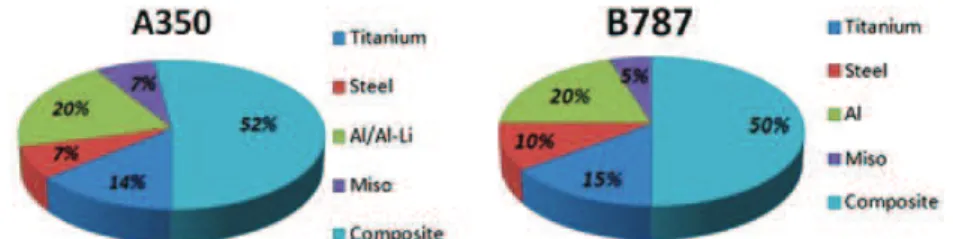
Especially, the forecast of the behaviour of composite material is a major point of optimization of the quality and the cost of the parts obtained by thermoforming. In the last 10years [3], there has been increasing use of reinforced composites in primary structural components of aircrafts such as Airbus A380, Boeing 777, coming Boeing 787 and coming Airbus A350 [4,5] (see Figures 1 and 2).
*Correspondence to: Fethi Abbassi, URMSSDT-ESST Tunis, 5 Avenue Taha Hussein, BP, 56, Bâb Manara, 1008 Tunisia. †E-mail: [email protected]
In the present work, we present an experimental attempt to evaluate the forming characteristics of woven composite. Several static uniaxial and biaxial tensile tests were carried out in high temperature condition.
In the second part, we will present a numerical simulation on thermostamping of woven composite sheets. The results of the experimental investigation were used to develop the numerical model of the mechanical test (to choose the biaxial tensile specimen geometry) and the composite thermoforming operation. Linear shell elements (ABAQUS[30] element type S4R) will be used to model the composite sheets and rigid elements to model the tools.
2. MATERIAL CHARACTERIZATIONS
Various deformation mechanisms can occur during forming of a sheet of textile composite material; the properties of woven fabrics are very different from conventional materials. In the woven composite forming process, the most dominant deformation mode is the intra-ply shear [6]. In weave character-ization procedure, many design experimental tests (bias-extension test, biaxial tensile test, trellis-frame test, etc.) were developed; particularly, the experimental investigations of Cao et al. [7] presented consistent results of benchmark tests, the last ones developed by seven international research institu-tions (i.e. Hong Kong University of Science and Technology (HKUST) in Hong Kong, Katholieke Universiteit Leuven (KUL) in Belgium, Laboratoire de Mécanique des Systèmes et des Procédés (LMSP) in France, Northwestern University (NU) in the USA, University of Massachusetts Lowell (UML) in the USA, University of Twente (UT) in the Netherlands and University of Nottingham (UN) in the UK. Usually the experimental data from such tests can play two important roles either in fitting the parameters of constitutive models derived from continuum mechanical assumptions or else in evalu-ating the accuracy of constitutive models based on a constituent-based predictive approach [6].
2.1. Material requirements
The material investigated in this study was carbon/polyphenilenesulfide (PPS) woven composite. The studied laminates were made of 5-harness satin weave pre-pegs plies with a fibre volume fraction of 50%. The PPS matrix reinforced by carbon fibre is widely used in high-performance applications such
Figure 1. Boeing 787 material distribution [25].
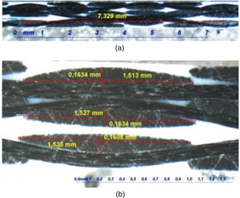
as aerospace, automobiles and aeronautic industries. For both cases, short-fibre and unidirectional long-fibre composites were treated at micro-scale and at macro-scale, but the textile composites have an additional level, meso-scale, to consider. Woven textiles are constructed by interlacing two orthog-onal sets of tows in a variety of weave topologies, such as satin, twill, matt and plain. The mechanical behaviour of woven reinforcements used in composites is mainly depending on weaving between warp and weft yarns. Figure 3 shows the weaving of the composite carbon/PPS (a) to visualize the weave topologies and (b) to represent the geometry of yarn in the cross section. The yarn dimensions, which were measured in three different locations of the laminate, revealed that the 5-harness satin weave weft yarn maintained its elliptical shape, with a major diameter of 1.52"0.15mm and the minor diameter
(a)
(b)
Figure 3. Photomicrograph of three-ply composite sheets. (a) Cross-sectional view of a 5-harness satin weave carbon–PPS, (b) geometry and dimensions of yarn.
varying at around 0.162"0.015mm. In Figure 4, we show the fibre distribution in the yarn, which was used to determine the value of carbon fibre diameter.
2.2. Thermo-gravimetric analysis of carbon/PPS
In order to increase the formability of composite sheet, the tested plates were heated. After discussion with industrialists and the thermo-gravimetric analysis results, we selected the optimal forming temper-ature of carbon/PPS composite at 320!C. Figure 5 shows the Differential Scanning Calorimetry (DSC) results of carbon/PPS; the temperature of vitreous transition is about 90!C, and the melting point of the carbon/PPS is 285!C. In order to avoid the degradation of the mechanical properties of material during cooling of the part, it is necessary to maintain the temperature constantly at 220!C for 10min. The use of the Thermal Gravimetric Analysis (TGA) by Ning et al. [8] prove that the degradation temperature of carbon/PPS is much higher than the forming temprature.
2.3. Experimental tensile and bias-extension tests
We start the experimental investigation with several simple tensile tests in different orientations (0!, 90!) and bias-extension test (Figure 6a). The bias-extension test involves clamping a rectangular piece of woven material such that the warp and weft directions of the tows are orientated initially at"45!to
the direction of the applied tensile force.
During the test, the specimens were heated at 320!C in order to bring them closer to the conditions of the forming process. The temperature on the surface of the sample was measured by using an infra-red camera. Also, a Digital Image Stereo-Correlation (DIC) technique was applied in order to measure
Figure 5. DSC results of carbon/PPS.
(b)
(a) (c)
Figure 6. (a) Tensile samples orientation in the composite sheet, (b) tensile samples before testing and (c) grey level.
the displacement fields in the specimen’s surface. The displacements of many points distributed on the surface of the object are calculated from the grey level (Figure 6c) analysis of the images. Several low-rate tensile tests were carried out in the laboratory using an Instron{tensile testing machine.
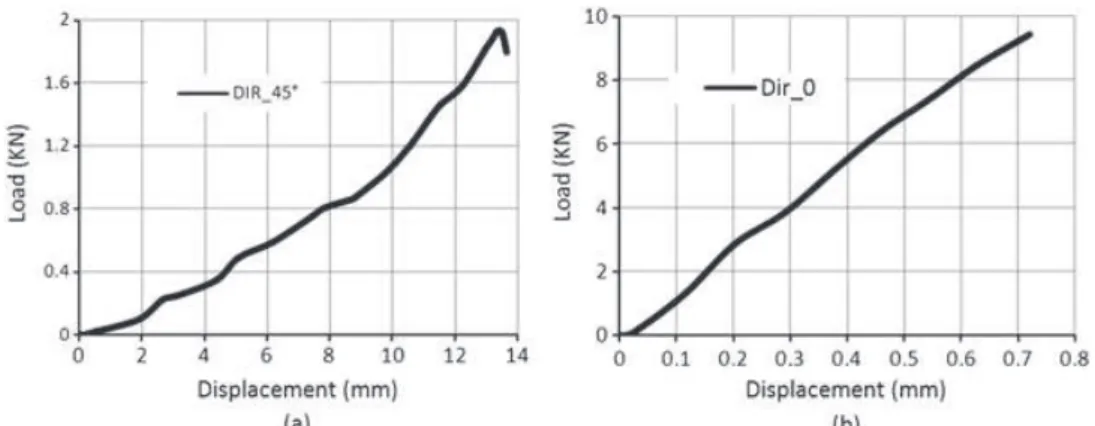
Figure 7a and b shows the load–displacement curves of the bias-extension test ("45!) and the
uni-axial tensile test (0/90!), respectively, for the two weave directions. In the first case, the displacement reached 13mm, which is explainable by the fibre rotation in the middle of the sample [9]. However, in the second case, the fibres were blocked in the bits of the machine, which limited the displacement to 0.8mm.
But we can consider that the axial deformation is the secondary important cause of deformation, although this behaviour cannot be neglected according to Boisse [10]. Woven materials exhibit an ini-tial non-linear stiffening caused by crimping in the yarns. When the fibres become aligned, the re-sponse becomes linear and is determined by the fibre characteristics. The importance of this phenomenon depends on the properties of the transverse yarns and in particular their resistance to com-paction. If the transverse yarns are also loaded, then the de-crimping zone will decrease in magnitude. Typical results are given by Boisse [11] for a plain weave fabric. When loaded uniaxially (i.e. ‘other free direction’), the non-linear region extends to a strain of approximately 0.5%, but the force to com-pletely straighten the yarn is low. As the ratio between strains in the tested (warp) and transverse (weft) directions increases, the force curve tends towards the behaviour of an individual yarn.
The use of the measurement equipment without contact, a charged coupled device (CCD) camera and commercial image correlation softwareARAMISW}allow the visualization of the strain distribution
in two different cases of fibre orientation; in Figure 8a, the fibre was oriented 0/90!with respect to the load axis, and Figure 8b represents the bias-extension test, the fibre oriented "45!to the load axis. In the first case, the distribution of strain in the specimen surface was homogeneous, but in the second case ("45!fibre orientation; Figure 8b), we observed a very heterogeneous deformation. It can be seen
from Figure 8c that the uniaxial tensile test specimen has three distinct regions: region A, pure shear zone; region B, undeformed zone of clamped fibres; and region C, zone of preferential slip and tow buckling. The shear angles should be measured or computed from the region [12-13]. In the DIC results of the specimen oriented"45!
with respect the load axis, the rotation of fibre starts at 4.3% of deformation; if the last phenomenon progresses, a homogeneous shearing zone takes place (noted in region A) in the centre of the sample (Figure 8b). In Figure 9, we can observe a huge difference be-tween initial and final orientations of the fibre in the central zone of tensile specimen, which explains the flexibility during the deformation of the weave.
2.4. Biaxial tensile test
A multi-axial system is used to develop the mechanical solicitation during the biaxial tensile test. This machine is an Instron 8800 biaxial. The capacity of this system is 100kN to each actuator with a frequency up to 200Hz with very small amplitudes. The configuration of the machine is made for cruciform specimens, and there is no restriction for specimen material (Figure 10).
According to the work presented by Smits et al. [14–21], a successful biaxial strength test with cruciform specimen required the following conditions:
1. Maximization of the region of uniform biaxial strain.
2. Minimization of the shear strains in the biaxial loaded test zone. 3. Minimization of the strain concentrations outside the test zone. 4. Specimen failure in the biaxial loaded test zone.
In this investigation, after several numerical models, we chose the geometry of the biaxial specimen [15] presented in Figure 11 .
In the experimental set-up of the biaxial test, the specimens were heated to 320!C, with two CCD cameras installed in order to measure the displacement field in the surface of specimens; to improve the luminosity of the zone work, a light source was embedded in the mediums of the two camera posi-tions. Also, an infrared camera was installed opposite to the heated zone to measure the temperature.
{
http://www.instron.tm.fr
(a) (b) (c) [9]
Uniform shearing zone
Figure 8. DIC results in uniaxial load: (a) direction at 0!/90!, (b) direction at +45!/#45!and (c) shearing
mech-anism in tensile specimen.
Figure 7. Load–displacement curve; (a) bias-extension test, (b) tensile test.
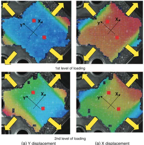
Figure 12 shows the experimental configuration. The distribution of displacement as illustrated in two different levels of rool (Figure 13) is shown in the cartography of displacement in the central zone of specimen with weave orientation at 0/90!.
Figure 14 shows the fracture mechanism of tow cases at"45!and 0/90!orientation of weave. In the
first case, the lengthening is large, but in the second the fibres are blocked in the tow directions by the bits of the biaxial machine, so that the displacement is very small. Also, we observe that the fracture started from the connection radios. By using the DIC, we observe that the biaxial deformation localized in the middle of specimen, which confirms the good choice of the specimen geometry.
At macroscopic level, a woven fabric can be seen as a continuous material with a very specific mechanical behaviour, including high anisotropy and the ability to exhibit very large shearing and bending deformations [16].
In order to determine the mechanical properties of composite material, we used a comparison procedure between the numerical and experimental curve ‘load–displacement’. For many times we modify the values of the parameters of FE model of the tensile test and we evaluate the results until we arrived at a satisfaction criterion. Table I presents the mechanical properties of carbon/PPS obtained by this identification procedure.
(a) (b)
Figure 11. (a) Geometry of the biaxial specimen; (b) the variable grey levels on the surface of a biaxial tensile specimen.
3. MODELING OF HEMISPHERICAL FORMING AND ANALYSIS
Due to the diversity of the used materials and the complex shapes created, the introduction of computer codes and the numerical analysis became a necessity. In fact, the implementation of a numerical model can significantly reduce conception times, a key issue in the developed industries. In addition,
Figure 12. Experimental set-up of biaxial tensile test.
1st level of loading
2nd level of loading
(a)Y displacement (a)X displacement X X Y X Y X Y X Y
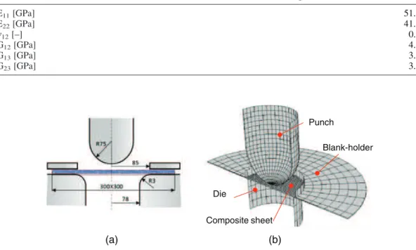
numerical simulation is an efficient way to improve the control of the thermoforming process and avoid problems which can occur, such as the tearing of the thermoformed sheet and the irregularity of the blank’s thickness distribution. Thus, importance must be given to the introduction of the main physical phenomena occurring during this process such as the failure, the wrinkling of sheet, the material’s constitutive law and the contact between model’s components, which greatly affect the results [17,18]. In the numerical section of this investigation, we will present the simulation of thermostamping of woven composite sheets through a full continuum mechanics approach. Figure 15a shows the typical tool geometry [20,21] used in the thermoforming model of thermoplastic reinforced by continuous car-bon fibre. We will use 7468 linear shell elements (S4R) to model the composite sheets represented by a 300$300mm plate (Figure 15b). We employ the material properties in Table I, and we use a compos-ite layup (three plies). The compaction force on the blank holder is 300N.
(a) (b)
Figure 14. Biaxial tensile sample after fracture (a) weave orientation at"45!, (b) weave orientation at 0!/90!.
Table I. Material characteristics for carbon/PPS composite.
E11[GPa] 51.08 E22[GPa] 41.34 n12[–] 0.03 G12[GPa] 4.12 G13[GPa] 3.5 G23[GPa] 3.5 (b) (a) Composite sheet Punch Blank-holder Die
Figure 15. Finite element model for hemispherical stamping simulation of woven fabric, (a) tool geometry, (b) nu-merical model.
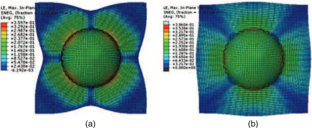
Two different configurations of hemispherical stamping operation are considered. Figure 16a and b shows the two final appearances of stamp thermoforming from top view. In the first, the composite considered had an orientation of weaving at 0/90!(Figure 16a); in the second case the fibre oriented at"45! (Figure 16b). A numerical study of the same application is presented in [22].
In the case of 0!/90! orientation weave, we observe a shortening of the matter on the level of the median of the plate, that is according to the same direction of fibres. This phenomenon is explained by the rotation of fibres and the variation of shear angle between the warp and the weft yarn. During shearing, significant changes appear in the geometry of the elementary mesh which generates a great deformation according to the diagonal direction of the mesh.
The thermoforming test of thermoplastic composite reinforced by carbon fibres showed that the fibres do not slip between them during the forming operation. Sometimes, a slip can take place, but it is the beginning of failure in the forming operation.
In the second configuration where the initial orientation of fibres is "45!, the flow of the matter is more significant according to the direction of the diagonal and limited according to the median direction, which is explained by the rotation of fibres in the first direction and the absence of phenomenon in the second. Because of this, several phenomena appeared in the final shape such as wrinkling. Shear in some regions goes beyond the limit of in-plane deformation; in this area we show the appearance of wrinkles (Figure 17).The presence of the wrinkles is noted: (i) first, in the diagonal part of the sheet, after form-ing in the case where the yarns’ orientation is 0°/90° (Figure 16-a), (ii) second, in the median part of the sheet, after forming in the case where the yarns’ orientation is ±45 (Figure 16-b). The zone of presence of wrinkles depends on the initial orientation of the angle between the yarns because the shearing
(a) (b)
Figure 16. Numerical results of stamp thermoforming: (a) weave orientation 0!/90!, (b) weave orientation"45!.
(b) (a)
Wrinkling zone
involves a reduction in the angle until the blocking and an increase the thickness at this zone. In many investigations, the authors used a wrinkling criterion to evaluate quantitatively the magnitude of wrinkling based on theoretical model. On the basis of the energy method, Zhu et al. [23] expressed this criterion:
wt⩽wrþ wsþ wc (1)
Where wtis the total energy, wris the energy dissipated by rotary friction of yarns, wsis the energy
dissipated by sliding friction of yarns and wcis the energy dissipated by transverse compression of
yarns. With wt¼ 4EI D þ PFw0 4 " # ' cosg wr¼ e0m !N 1þ 3g 2p " # ffiffiffiffiffiffiffiffiffi cosg p r ws¼ 2w0m!P gð Þ cosg wc¼ 2w0!P gð Þ sing 8 > > > > > > < > > > > > > :
Where F is the additional force along yarns, g is the inter yarn shear angle, !Nis the normal compressive force between yarns, e0the initial yarn width, m the frictional coefficient between yarns and !Plateral
compressive force between yarns.
Because it is not convenient to directly measure the forces during the forming operation, we use this relation to determine the tensile force along yarns:
F¼ Ee'npD
2
4 (2)
Where E is the elastic module of the yarn, D is the diameter of fibre, e is the strain along the yarn and nis the number of fibres in a yarn.
Boisse et al. [24,27–29] developed an analysis of wrinkles in the woven composite, and they proved the very sensitive to in-plane compression loadings. Wrinkles phenomena are due to all strains and rigidities of the fabric (tension, in-plane shear and bending) and to boundary conditions. A blank holder can increase the tensions and consequently avoid wrinkling [24].
4. CONCLUDING REMARKS
In this investigation, a pre-impregnated woven composite was used. This material carbon/PPS has many applications particularly in the aircraft structure and the aerospace industry.
Firstly, an experimental work was developed, starting with the thermo-gravimetric analysis of car-bon/PPS. According to the results of this analysis, the bibliography study and the discussion with industrialists, we chose 320!C as the optimal temperature of thermoforming of carbon/PPS composite. In addition, several mechanical tests were developed, and uniaxial and biaxial specimens were pre-pared in different orientations of weave. During these tests which were carried out respectively on two uniaxial and biaxial tensile testing machines (Instron in LGP laboratory), a DIC method was used to evaluate the displacement in the specimen’s surfaces. These tests were elaborated in high tempera-ture condition, and an infrared camera was used to measure the temperatempera-ture during the test. The results extracted from this experiment were analysed.
We also performed hemisphere forming simulation which is a classic test for the forming simula-tion. In this section, we used the experimental results in the numerical model in order to evaluate the formability of this material and to analyse the phenomena present during the thermoforming operation. Experimental results extracted from the bibliography was presented in order to prove the numerical ob-servation. Above all, this paper shows how numerical simulation can greatly improve understanding of the forming process, particularly the wrinkling phenomenon which was studied in the last section. Thus, wrinkling occurred in the same region in the numerical and experimental results due to local buckling of tows. In addition, we presented a theoretical criterion based on energy method to predict when the wrinkling happens.
REFERENCES
1. Suong DG, Stephen VH, Tsai W. Composite Materials Design and Applications. CRC PRESS, 2003.
2. de Lucas P, Lefébure P, Pickett AK. Numerical and experimental investigation of some press forming parameters of two fibre reinforced thermoplastics: APC2-AS4 and PEICETEX. Composites Part A 1998; 29:101–110.
3. Dumont F, Weimer C, Soulat D, Launay J, Chatel S, Maison-Le-Poec S. Composites preforms simulations for helicopters parts. International Journal of Material Forming 2008; Suppl 1:847–850.
4. Marsh G. Airbus Takes on Boeing with Reinforced Plastic A350 XWB, Reinforced Plastics. vol. 29, Elsevier, December 2007.
5. Wang WX, Nakata M, Takao Y, Matsubara T. Experimental investigation on test methods for mode II interlaminar fracture testing of carbon fiber reinforced composites. Composites: Part A (2009).
6. Long AC. Design and Manufacture of Textile Composites. CRC Press, 2005.
7. Cao J, Akkerman R, Boisse P, Chen J, Cheng HS, de Graaf EF, Gorczyca JL, Harrison P, Hivet G, Launay J, Lee W, Liu L, Lomov SV, Long A, de Luycker E, Morestin F, Advoiskis J, Peng XQ, Sherwood J, Stoilova TZ, Tao XM, Verpoest I, Willems A, Wiggers J, Yu TX, Zhu B. Characterization of mechanical behavior of woven fabrics: experimental methods and benchmark results. Composites: Part A 2008; 39:1037–1053.
8. Ning H, Vaidya U, Janowski GM, Husman G. Design, manufacture and analysis of a thermoplastic composite frame struc-ture for mass transit. Composite Strucstruc-tures 2007; 80:105–116.
9. Boisse P, Akkerman R, Cao J, Chen J, Lomov S, Long A. Composites Forming, Advances in Material Forming—Esaform 10Years On. Springer, ISBN: 978-2-287-72142-7.
10. Boisse P, Borr M, Buet K, Cherouat A. Finite element simulations of textile composite forming including the biaxial fabric behaviour. Composites Part B 1997; 28–4:453–464.
11. Boisse P, Gasser A, Hivet G. Analyses of fabric tensile behaviour: determination of the biaxial tension-strain surfaces and their use in forming simulations. Composites Part A 2001; 32–10:1395–1414.
12. Peng X, Ding F. Validation of a non-orthogonal constitutive model for woven composite fabrics via hemispherical stamping simulation. Composites: Part A 2011; 42:400–407.
13. Potluri P, Perez Ciurezu DA, Ramgulam RB. Measurement of meso-scale shear deformations for modelling textile compo-sites. Composites: Part A 2006; 37:303–314.
14. Van Hemelrijck AD, Philippidis TP, Cardon A. Design of a cruciform specimen for biaxial testing of fibre reinforced com-posite laminates. Comcom-posites Science and Technology 2006; 66:964–975.
15. Banabic D, Aretz H, Comsa DS, Paraianu L. An improved analytical description of orthotropy in metallic sheets. Interna-tional Journal of Plasticity2005; 21:493–512.
16. Boisse P, Aimène Y, Dogui A, Dridi S, Gatouillat S, Hamila N, Aurangzeb Khan M, Mabrouki T, Morestin F, Vidal-Sallé E. Hypoelastic, hyperelastic, discrete and semi-discrete approaches for textile composite reinforcement forming. International Journal of Material Forming2009; doi:10.1007/s12289-009-0664-9.
17. Boisse P, Hamila N, Helenon F, Hagege B, Cao J. Different approaches for woven composite reinforcement forming sim-ulation. International Journal of Material Forming 2008; 1:21–29, doi:10.1007/s12289-008-0002-7.
18. Chen QQ, Boisse P, Hamila N, Saouab A, Park CH, Bréard J. A finite element method for the forming simulation of the reinforcements of thermoplastic composite. International Journal of Material Forming 2009; Vol. 2(Suppl 1):213–216. 19. Sargent J, Chen J, Sherwood J, Cao J, Boisse P, Willem A, Vanclooster4 K, Lomov SV, Khan M, Mabrouki3 T,
Fetfatsidis K, Jauffrès D. Benchmark study of finite element models for simulating the thermostamping of woven-fabric reinforced composites. International Journal of Material Forming 2010; Vol. 3(Suppl 1):683–686.
20. Aimène Y, Vidal-Sallé E, Hagège B, Sidoroff F, Boisse P. A hyperelastic approach for composite reinforcement large de-formation analysis. Journal of Composite Materials 2010; Vol. 44n!1:5–26.
21. Demmerle S, Boehler JP. Optimal design of biaxial tensile cruciform specimens. Journal of the Mechanics and Physics of Solids1993; 41:143–181.
22. Chen Q, Boisse P, Hae CAbdelghani SaouabP, BréardJ. Intra/inter-ply shear behaviors of continuous fiber reinforced ther-moplastic composites in thermoforming processes. Composite Structures 2011; 93:1692–1703.
23. Zhu B, Yu TX, Zhang H, Tao XM. Experimental investigation of formability of commingled woven composite preform in stamping operation. Composites: Part B 2010; doi:10.1016/j.compositesb.2010.05.006.
24. Boisse P, Hamila N, Vidal-Sallé E, Dumont F. Simulation of wrinkling during textile composite reinforcement forming. In-fluence of tensile, in-plane shear and bending stiffnesses. Composites Science and Technology 2011; 71:683–692. 25. Campbell FC. Manufacturing Technology for Aerospace Structural Materials. Elsevier, 2006.
26. Wakeman MD, Zingra L, Bourban PE, Manson J-AE, Blanchard P. Stamp forming of carbon fibre/PA12 composites—a comparison of a reactive impregnation process and a commingled yarn system. Composites Science and Technology 2006; 66:19–35.
27. Allaoui S, Boisse P, Chatel S, Hamila N, Hivet G, Soulat D, Vidal-SalleE. Experimental and numerical analyses of textile reinforcement forming of a tetrahedral shape Composites: Part A 2011; 42:612–622.
28. Zouari B, Daniel JL, Boisse P. A woven reinforcement forming simulation method. Influence of the shear stiffness Compu-ters and Structures2006; 84:351–363.
29. Boisse P, Zouari B, Gasser A. A mesoscopic approach for the simulation of woven fibre composite forming Composites Sci-ence and Technology2005; 65:429–436.