HAL Id: hal-02174649
https://hal.archives-ouvertes.fr/hal-02174649
Submitted on 15 Jul 2019
HAL is a multi-disciplinary open access
archive for the deposit and dissemination of
sci-entific research documents, whether they are
pub-lished or not. The documents may come from
teaching and research institutions in France or
abroad, or from public or private research centers.
L’archive ouverte pluridisciplinaire HAL, est
destinée au dépôt et à la diffusion de documents
scientifiques de niveau recherche, publiés ou non,
émanant des établissements d’enseignement et de
recherche français ou étrangers, des laboratoires
publics ou privés.
Domain-Level Observation and Control for Compiled
Executable DSLs
Erwan Bousse, Manuel Wimmer
To cite this version:
Erwan Bousse, Manuel Wimmer. Domain-Level Observation and Control for Compiled Executable
DSLs. IEEE / ACM 22nd International Conference on Model Driven Engineering Languages and
Systems (MODELS), Sep 2019, Munich, Germany. �hal-02174649�
Domain-Level Observation and Control for
Compiled Executable DSLs
Erwan Bousse
University of Nantes – LS2N, France Email: [email protected]
Manuel Wimmer
CDL-MINT, Johannes Kepler University Linz, Austria Email: [email protected]
Abstract—Executable Domain-Specific Languages (DSLs) are commonly defined with either operational semantics (i.e., in-terpretation) or translational semantics (i.e., compilation). An interpreted DSL relies on domain concepts to specify the possible execution states and steps, which enables the observation and control of executions using the very same domain concepts. In contrast, a compiled DSL relies on a transformation to an arbitrarily different target language. This creates a conceptual gap, where the execution can only be observed and controlled through target domain concepts, to the detriment of experts or tools that only understand the source domain. To address this problem, we propose a language engineering architecture for compiled DSLs that enables the observation and control of executions using source domain concepts. The architecture requires the definition of the source domain execution steps and states, along with a feedback manager that translates steps and states of the target domain back to the source domain. We evaluate the architecture with two different compiled DSLs, and show that it does enable domain-level observation and control while increasing execution time by 2× in the worst observed case.
Index Terms—Software Language Engineering,
Domain-Specific Languages, Executable DSL, Compilation, Feedback
I. INTRODUCTION
A large number of Domain-Specific Languages (DSLs) can be used to describe the dynamic aspects of systems (e.g., [1]– [4]). In that context, early dynamic verification and validation (V&V) techniques, such as omniscient debugging [5], test-ing [6], or tractest-ing [7] are necessary to ensure that models conforming to such languages are correct. These techniques require models to be executable, which can be achieved by defining the execution semantics of the DSLs used to define them. To that effect, a lot of efforts have been made to provide facilities to design so-called executable DSLs (e.g., [8]–[12]), which can be used to define executable models. More pre-cisely, two different approaches are commonly used to define the semantics of an executable DSL: operational semantics (i.e., interpretation) and translational semantics (i.e., compila-tion). In this paper we are interested in both approaches, and we specifically focus our work on discrete-event semantics.
All previously mentioned V&V approaches rely on two key tasks: the observation of the progress of the execution (e.g., which execution steps are occurring), and the control of the execution (e.g., pausing and resuming). With an in-terpreter, the dynamic state of a model conforming to the DSL is defined along with the possible execution steps that modify such state over time. These definitions can directly
rely on domain-specific concepts, opening the possibility to observe and control executions from a domain perspective (e.g., visualizing the active state of a state machine). However, with a compiler, a model conforming to the DSL is translated into another executable language. By default, observing the resulting execution yields information specific to the target language instead of the considered DSL, i.e., there is no feedback at the domain level. For instance, when code is generated from a model, it is common to rely on an interactive debugger of the target language, but without the possibility to directly relate information back to the original model.
While ad-hoc solutions have been proposed for both com-piled programming languages (e.g., jdb translates bytecode-level information back to the Java-bytecode-level) and compiled mod-eling languages (e.g., several UML code generators provide model-level feedback [13]), there is to our knowledge no systematic approach to provide domain-level observation and control for any compiled DSL. Having such an approach would in addition enable the use and reuse of a wide range of runtime services—i.e., tools that provide dynamic V&V— at the domain-level of compiled DSLs. However, to obtain such benefits, some important challenges must be considered: (1) the same level of observation and control must be provided for compiled DSLs as what is possible for interpreted DSLs; (2) the use of a wide range of runtime services must be possible with compiled DSLs, and, to reduce development efforts, the reuse of the same runtime services must be possible among both interpreted and compiled DSLs; (3) the overhead on the execution time must be as small as possible.
To address these challenges, we propose a language engi-neering architecture where a compiled DSL is supplemented with a feedback manager, which relies on traceability links to translate execution steps and states of the target language back into the original domain. This feedback manager is connected to the ongoing execution of the target model, and thus provides domain-level feedback at execution time. Runtime services (e.g., an interactive debugger or a tracer) may be attached to the feedback manager in order to continuously observe and control the execution at the domain-level. In addition, runtime services can interchangeably be used both for interpreted and compiled DSLs. To limit the overhead during the execution, the state of the source model is only modified when changes occur in the state of the target model.
framework of the GEMOC Studio, an Eclipse-based language and modeling workbench. Our evaluation relies on the appli-cation of the proposed architecture on two different compiled DSLs: first a subset of fUML activity diagrams compiled to Petri nets, and second, a subset of UML state machines compiled to MiniJava. Results show that two existing runtime services initially targeting interpreted DSLs can be used for both DSLs, while increasing execution time by 2x in the fUML case, and by 1,01x in the UML state machines case.
Section II defines the scope of considered executable DSLs. Section III gives an overview of the architecture, which is then presented in Section IV. Section V presents our evaluation. Section VI compares the related work with our approach. Finally, Section VII concludes with research directions.
II. EXECUTABLEDSLS
A. Abstract Syntax
We focus in this paper on metamodel-based DSLs, i.e., DSLs whose abstract syntaxes are metamodels defined using metamodeling languages (e.g., MOF [14] or Ecore [15]). Definition 1. A metamodel is composed of a set of meta-classes, each composed of a set of properties typed either by another metaclass or by a primitive type.
Accordingly, amodel conforming to a metamodel takes the form of an object graph where each object is an instance of a metaclass of the metamodel. An object is composed of fields, each setting the value of a corresponding property.
The top-left corner of Figure 1 shows the abstract syntax of a Petri nets DSL. It contains three metaclasses: Net,Place
andTransition. Each metaclass contains properties; for instance
Net contains a set of Placeand Transitionobjects through the places and transitions properties.
B. Interpreted DSL
An interpreted DSL is based on an operational semantics, in which we distinguish three main constituents.
First, the possible execution states of models conforming to an interpreted DSL must be defined. This is commonly accomplished either by extending the abstract syntax with dynamic properties and metaclasses [9], [16]—in which case the state is part of the executed model—or by defining a separate metamodel [17]—in which case the state is a separate model. While our proposed architecture remains valid with both approaches, our examples in this paper rely on the first one, i.e., the possible states are defined by extending the abstract syntax with new dynamic properties and metaclasses. Second, we call interpretation rules what defines how the state of an interpreted model changes over time. Such rules can be defined using a wide range of model transformation techniques (e.g., Java or Xtend with EMF [15], Kermeta [16], xMOF [9], ATL [18], [19], etc.).
Third, the possible execution steps that may occur during the interpretation of a model must be defined. We call an execution step a set of observable changes applied on the model state. Accordingly, the model state is considered to be
only observable either just before or just after the changes embodied by a step were performed. A step also carries data such as a name (e.g., “fire” step for when a transition is fired, “call” step for when a method is called) and data on the elements involved in a step (e.g., the transition that was fired, the method that was called). A step can be composite, in which case the only changes it carries are those of its children steps. Execution steps are produced at runtime by the interpretation rules of the DSL, and can be used as input data by runtime services (e.g., monitoring, tracing, interactive debugging) to observe the execution progress. The possible execution steps of an interpreted DSL can be defined in various ways, e.g., by considering that each interpretation rule produces a kind of step, or by defining step types in a separate model.
To summarize, the interpreted DSLs considered in the scope of this paper can be defined in the following way:
Definition 2. An interpreted DSL is defined by the following elements: (1) Anabstract syntax, that is a metamodel. (2) An operational semantics (or interpreter), with: a) A model state definition, b) A set of interpretation rules, c) A definition of execution steps that are produced by the interpretation rules. Figure 1 shows an example of a interpreted Petri nets DSL. Next to the abstract syntax—described in Section II-A— the model state definition is shown. It is a metamodel that extends the metaclassPlace using package merge with a new dynamic property tokens. At the right, short descriptions of the interpretation rules are depicted. When called, these rules change the tokens fields of the different Place objects, with runbeing the entry point of the execution. Each rule defines a kind of step, e.g., an application of the fire rule produces a step called “fire” pointing to the Transition that was fired. When applied, the fire rule consumes tokens from all input
Place elements of a given Transition, and produces tokens in all its outputPlaceelements.
Lastly, executing a model conforming to an interpreted DSL consists in creating an initial state, and in running the interpretation rules that will both change this state over time and produce steps. We call observation point an instant in the execution reached just before or just after each step.
Figure 2 presents an execution trace of a Petri net conform-ing to the Petri net interpreted DSL shown in Figure 1. The trace is composed of four model states (fromAtoD), on top of which the steps of the execution are depicted as arrows. Three steps where produced by the applications of the fire step rule. They are enclosed in a larger step that goes from the first model state (A) to the last model state (D), which is the application of the run rule. The possible observation points (from1 to6) are depicted in diamond shapes.
C. Compiled DSL
A compiled DSL is based on a translational semantics, i.e., a model transformation from the abstract syntax of the considered DSL, to the abstract syntax of another executable target language. As compared to an interpreted DSL, a com-piled DSL does not explicitly define how the execution is
Abstract Syntax input 1..* output 1..* Net Place name: String initialTokens: Integer Transition name: String places * merges imports
Model State Definition
Place
tokens: Integer
Interpretation rules (summarized)
run(Net)
fire(Transition): while there is an enabled transition, fires it.: removes a token from each input Place and adds one to each output Place. *
transitions
Figure 1: Petri nets interpreted DSL
p4 p5 t1 t2 t3 p1 p3 p2 p4 p5 t1 t2 t3 p1 p3 p2 p4 p5 t1 t2 t3 p1 p3 p2 p4 p5 t1 t2 t3
fire(t1) fire(t2) fire(t3)
run(net) A B C D 1 2 3 4 5 6 p3 p1 p2 A model state step foo() 1 observationpoint
Figure 2: Example of execution trace of a Petri net model conforming to the Petri net DSL shown in Figure 1.
Petri nets abstract syntax AD abstract syntax Activity Edge
Action ForkNode JoinNode
InitialNode FinalNode <<abstract>> NamedElement +name: String source 1 target 1 outgoing * incoming * nodes * edges * <<abstract>> Node transformActivity(Activity) transformEdge(Edge) transformAction(Action) ... : Creates a Net : Creates a Place
: Creates a Place and two Transitions imports
Compiler (summarized) imports
Figure 3: Activity Diagram compiled DSL, which uses the Petri net DSL shown in Figure 1 as a target language
performed in terms of states and steps of the source domain, and relies instead on the execution of target models obtained after compilation. In summary, the compiled DSLs considered in the scope of this paper are defined as follows:
Definition 3. A compiled DSL is composed of: (1) An abstract syntax, that is a metamodel. (2) A translational semantics (or compiler), that is a model transformation from the abstract syntax of the compiled DSL, to the abstract syntax of another executable language.
Figure 3 shows an example of an Activity Diagram com-piled DSL which uses the Petri nets DSL from Figure 1 as a target language. This example is a simplified version of the part of fUML [1] related to the control flow of activities. The proposed translational semantics is inspired from several approaches aiming at translating UML activities and process models to Petri nets [20], [21]. At the top, the abstract syntax defines an Activityas a set of inter-connected Node andEdge
objects, with several types of nodes.InitialNodeandFinalNode
mark the beginning and the end of the Activity. A ForkNode
starts concurrent execution branches, which can be joined back in a JoinNode. AnActionrepresents an opaque action realized
A B C e1 e2 e3 e4 e5 e6 e7 Init End J F
Figure 4: Example of an activity conforming to the compiled DSL shown in Figure 3.
in the process. The semantics of activities are based on a token flow, which we summarize below with an example.
Figure 4 shows an example ofActivity. Init is anInitialNode, which creates the initial token, and End is a FinalNode. Next, e1–e7are Edgeelements, and receive tokens offered by their source Node elements. If there are offered tokens on all its incomingedges, aNodetakes the tokens and offers new ones to its outgoing edges. A,B and C are Action nodes, F is a
ForkNode, and J is a JoinNode. Figure 5 shows the Petri net model obtained after compiling the activity shown in Figure 4. Finally, executing a model conforming to a compiled DSL is the compilation of this model into a model conforming to the target language, and the execution of the obtained model.
III. OVERVIEW
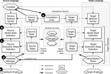
This section shows an overview of the proposed architec-ture. The idea is to observe the execution of the target model obtained by compilation, and translate target states and steps back to the source domain. Figure 6 depicts this architecture. a) Assumptions: The compiled DSL follows the defini-tion given in Secdefini-tion II-C, hence it is metamodel-based, with a compiler defined as a model transformation. Second, the target language is a metamodel-based interpreted language1 that follows the definition given in Section II-B. Thus, the target language is able to produce execution steps that can then be sent to runtime services (e.g., trace construction, interactive debugging) attached to the execution. These steps are sent in a synchronous fashion, which means that attached services may
1Note that the target language may also be compiled as long as it follows the presented approach, i.e., it is possible to chain the application of our approach. For clarity, we always describe the target language as an interpreted language.
Init_node Init_offer e1_edge A_take A_node A_offer e2_edge F_take F_node e3_edge e4_edge F_offer B_node C_node B_take C_take B_offer C_offer e5_edge e6_edge
J_take J_node J_offer e7_edge End_take
Figure 5: Petri net produced by the compilation of the activity from Figure 4, conforming to the interpreted DSL from Figure 1.
Compilation Results Runtime services Target Language Source Language Source Abstract Syntax Compiler Source Model Compilation Links Target Model Target Abstract Syntax Target Model State Definition Source Model State Definition Target Execution Steps Definition Source Execution Steps Definition Feedback Manager Interpretation Rules Source State Target State Tracer Debugger Source Steps Source Steps
Source Steps Target Steps
... Target Engine Feedback Engine Target runtime data Source runtime data + Compilation Links T arget interpreter Model Procedure dependency conforms to input/output a b c d e
Figure 6: Overview of the architecture.
safely observe (e.g., access the model state) and control the execution (e.g., pause the thread) when informed of starting or ending steps. Consequently, we only focus on single-threaded executions. Note that while both source and target languages are depicted here in the same metamodel-based technical space, the presented architecture can be adapted for target languages that are not metamodel-based, as long as target execution steps can be observed synchronously and as long as the target execution state is observable.
b) Compilation: At the top of Figure 6, the compilation follows what was presented in Section II-C. On the left, the considered source DSL is based on a compiler relying on the DSL abstract syntax. The compiler produces a target model conforming to the abstract syntax of the target language, shown on the right. The architecture also requires the compiler to produce a set of compilation links a conforming to a traceability metamodel. This part is described in Section IV-A. c) Compiled DSL with Feedback Management: On the left, to provide feedback to the source model, the considered compiled DSL is supplemented with three additional parts. First, a source model state definition b is required to define what are the possible states of the source domain. Second, a source execution steps definition c must define what are the possible execution steps of the source domain. Third, the feed-back manager d is responsible for translating execution steps occurring in the target model into execution steps occurring in the source model, and for updating the source model’s state accordingly. These three parts are at the core of the architecture for defining compiled DSLs proposed in this work, and are described in Sections IV-B, IV-C and IV-D.
Link MM language Object links * source 1..* target 1..* element 1 LinkEnd +annotation: String link 1 TraceabilityModel
Figure 7: Generic traceability metamodel
A
e1 e2
Init End
Init_node
Init_offere1_edgeA_take A_nodeA_offere2_edgeEnd_take
"offer"
"take" "offer" "take" Activity diagram Traceability model Petri net "place" "place" "place" "place" "node"
"node" "edge" "edge""node"
Figure 8: Example of activity compiled to a Petri net, with a traceability model. Each gray triangle represents aLink.
d) Execution with Feedback: On the right, the interpreter of the target language is used to execute the target model, which consists in modifying the target model state and in producing target steps. These target steps must then be sent to the feedback manager—or any other runtime service at-tached to the execution of the target model—to be translated into source execution steps and states. For this purpose, a component called the target execution engine receives target execution steps produced by the target interpreter, and transmit them to all runtime services attached to the execution. The feedback manager is considered to be a specific runtime service attached to the target executing engine, and as such can continuously receive all produced execution steps to perform its tasks. Lastly, a second execution engine called the feedback engine e is responsible for listening to the feedback manager, and for relaying notifications to runtime services attached at the source compiled DSL level. Thereby, for instance, an interactive debugger can be attached to the feedback engine in order to debug the source model at the domain-level during the execution. This part is described in Section IV-E.
IV. COMPILEDDSL ARCHITECTURE
This section presents each part of the proposed architecture: first the management of traceability, then the definition of source states and steps, and lastly the feedback manager. A. Compilation and Traceability Management
In Section II-C, we defined the main constituents of a compiled DSL. However, our approach requires that a
com-AD execution metamodel Token <<abstract>> Node Edge heldTokens * merges Activity diagram abstract syntax <<abstract>> TokenHolder
Figure 9: Activity diagram model state definition, added to the DSL to define the states of conforming models.
piler not only produces a target model, but also produces a set of compilation links (labeled a in Figure 6), i.e., a traceability model that relates produced target elements to their originating source elements. This is required in later stages to be able to relate execution states and steps of the target model back to the source model. We require a traceability metamodel allowing both many-to-many links and annotations to uniquely identify the elements in a many-to-many traceability link. Figure 7 shows one possible generic traceability metamodel that satisfies this constraint, where each
Linkelement connects source objects of the source model and target objects of the target model. Annotations can be used to distinguish elements and links as necessary. Figure 8 shows an example of traceability model produced by the compilation of a simple activity diagram. The sourceActionAis connected to two Transition elements: one annotated "take" since it represents the incoming edge of an action used for taking nodes from preceding nodes, and one annotated "offer" since it represents the outgoing edge of an action used for offering tokens to successive nodes.
B. Source Model State Definition
A compiled DSL is mostly defined by a compiler, while everything related to execution is delegated to the target language. Yet, observing the execution of a model requires an access its state as it changes. It is therefore necessary to define the possible states of models conforming to a compiled DSL. For interpreted DSLs, possible states are defined by the model state definitionwhich extends the abstract syntax of the DSL with dynamic properties and metaclasses. Following this idea, our architecture extends a compiled DSL with a model state definition of its own (labeled b in Figure 6).
Figure 9 shows the model state definition for the activity di-agram compiled DSL introduced in Figure 3. Using a package merge, it extends the abstract syntax of the DSL with a new dynamic metaclass Token, and extends the two metaclasses
NodeandEdgewith a dynamic property heldTokens using a common super type TokenHolder. In other words, at a given instant, the nodes of an activity may hold tokens, and edges may contain tokens offered by their source nodes.
C. Source Execution Steps Definition
While adding a model state definition to a compiled DSL is required for observing the state of a compiled model (e.g., to know where tokens can be found in the model), observing and controlling the execution of the model also requires knowing about the execution steps that occur in the model (e.g., which
Runtime Step Metamodel
StepStart <<abstract>> Value <<abstract>> PrimitiveValue ReferenceValue parameterValues * Modeling Runtime Object referencedObject 1 StepEnd start 1
Step Definition Metamodel
StepDefinition +name: String definition 1 changedObjects * Metamodeling language Metaclass parameters * StepParameter +name: String type 1 <<abstract>> Classifier +name: String PrimitiveType StepParameterValue value 1 parameter *
Figure 10: Step definition metamodel, and runtime step meta-model. The subtypes ofPrimitiveValueare not shown.
nodes offered the tokens). In the case of interpreted DSLs, such possible steps are defined by the execution steps definition (see Section II-B) that lists what are the possible types of execution steps, and what data and name they can carry. Following this idea, our architecture extends a compiled DSL with a steps definition of its own (labeled c in Figure 6).
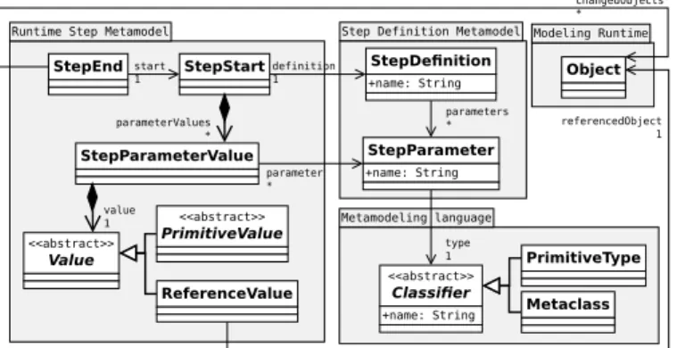
While the possible execution steps of an interpreted DSL can notably be declared through dedicated interpretation rules, a compiled DSL requires a formalism to explicitly declare its possible source execution steps. For that purpose, the top right corner of Figure 10 shows a simple step definition metamodel that can be used to define the possible execution steps of a DSL (note: the left and middle parts of Figure 10 are described in Section IV-D). AStepDefinition defines one type of execution steps through a name and a set of StepParameter elements. A StepParameter also has a name and is typed either by a
Metaclass—from the abstract syntax or from the model state definition—or by aPrimitiveType(e.g., Integer, String).
As an example, for the activity diagram compiled DSL introduced in Figure 3, we consider the following source
StepDefinitionelements, each with the type of its single Step-Parameter shown between parentheses: offer(Node) for the offering of tokens of aNodeto the outgoing edges of theNode; take(Node) for the taking of tokens by aNodefrom the incom-ing edges of theNode; executeNode(Node) for the taking and offering of tokens by aNode, i.e., a composite step containing both an offer step and a take step; executeActivity(Activity) for the execution of the Activityuntil no tokens can be offered or taken, i.e., a composite step containing executeNode steps.
D. Feedback Manager
The feedback manager is responsible of translating states and steps of the target model back to the source model. Feedback management is specific to the compiled DSL: only the language engineer knows how target steps and states should be translated to source states and steps. This approach offers to concentrate this knowledge in a manually defined feedback manager (labeled d in Figure 6) specific to the considered compiled DSL.
The feedback manager must be informed of starting and ending target steps, and it has to react to such steps by changing the source model state and creating corresponding source execution steps. Furthermore, it requires access to the generated execution links. A feedback manager can be divided into the following services that must be called at the start and at the end of target execution steps:
• feedbackState: Update the source model state based on the set of changes applied on the target model state in the last target execution step. For efficiency reasons, change notifications such as those provided by the Eclipse Mod-eling Framework (EMF) [15] can be used for determining target model changes.
• processTargetStepStart: Translate a target starting step
into source steps. Depending on the correspondences between target steps and source steps, it may produce zero, one or several source steps.
• processTargetStepEnd: Translate a target ending step into source steps. Again, depending on the correspondences between target steps and source steps, it may produce zero, one or several source steps.
Based on the runtime step metamodel shown in the middle of Figure 10, a StepStart element is produced when an ex-ecution step starts, and references both a StepDefinition from the execution steps definition of the DSL (e.g., the rule fire from Figure 1), and a set of parameters (e.g., a reference to the Transitionthat was fired). A StepEndelement is produced when an execution step ends, and references both theStepStart
of the step that is ending, and the set ofObjectelements from the model state that changed during this step.
We present in what follows a possible feedback manager for the activity diagram compiled DSL shown in Figure 3. Regarding the feedback of states, the tokens in each target Petri net Place must be translated back into Tokens objects in source TokenHolder elements. Regarding the feedback of steps, we consider the following mapping: (1) executeActivity is translated back from the corresponding run target step. (2) offer is translated back from the corresponding fire target step. (3) take is translated back from the corresponding fire target step. (4) executeNode is translated back from one or two fire target steps, based on the kind of Node.
For the pseudo-code we assume that the following op-erations are available: (1) getLinkEnd retrieves from the traceability model the LinkEnd corresponding to an object; (2) createStepStart produces a source StepStart by retrieving the required StepDefinition, and pushes this StepStart object atop an internal stack; (3) createStepEnd produces a source
StepEnd object, then retrieves and remove the latestStepStart
pushed atop the internal stack and assigns it to the StepEnd, then retrieves all objects that have changed in the model state since the last call to createStepEnd and assign them to the
StepEnd. (4) stepStart and stepEnd transmit source steps to the feedback engine, which itself relays source steps to attached runtime services (e.g., an interactive debugger). The feedback engine is explained in more details in Section IV-E.
Algorithm 1: Example of feedbackState definition for the activity diagram compiled DSL
Input:
stepEndt: the targetStepEndobject to process links: the execution links
1 begin
2 changed← stepEndt.changedObjects 3 foreach place ∈ changed do
4 tokenHolder← getLinkEnd(place).link.source[0].object
5 diff← place.tokens − size(tokenHolder.heldTokens)
6 for i ← 1; i≤ |diff |; i ← i + 1 do
7 if diff > 0 then
8 tokenHolder.heldTokens.add(createObject(Token))
9 else
10 tokenHolder.heldTokens.remove(source.heldTokens[0])
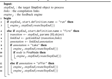
Algorithm 2: Example of processTargetStepStart def-inition for the activity diagram compiled DSL
Input:
stepStartt: the targetStepStartobject to process links: the compilation links
enginef: the feedback engine
stepsDefs: the source execution steps definition
1 begin
2 if stepStartt.definition.name = "run" then
3 net← stepStartt.params [0].object
4 act← getLinkEnd (net,links).link.source [0].object
5 enginef.stepStart (createStepStart (stepsDefs,"executeActivity", [act]))
6 else if stepStartt.definition.name = "fire" then 7 transition← stepStartt.params [0].object 8 linkEnd← getLinkEnd (transition,links)
9 annotation← linkEnd.annotation
10 node← linkEnd.link.source [0].object
11 if annotation = "take" then
12 enginef.stepStart (createStepStart (stepsDefs,"executeNode", [node]))
13 enginef.stepStart (createStepStart (stepsDefs,"take", [node]))
14 else if annotation = "offer" then
15 if node isInitialNodethen
16 enginef.stepStart (createStepStart (stepsDefs,"executeNode", [node])) 17 enginef.stepStart (createStepStart (stepsDefs,"offer", [node]))
First, Algorithm 1 shows the definition of the feedbackState service, which creates or deletesTokenelements in the source model state, based on the amount of tokens in the changed
Placeelements in the target model state.
Second, Algorithm 2 shows the definition of the processTar-getStepStartservice. If a target Petri net run step is starting for aNetelement, then an activity diagram executeActivity step is sent as feedback. This feedback requires the Activityelement from which the Net was created, which is found using the traceability links. In the case of a starting fire target step, the feedback depends on which Petri net Transition is (or was) fired, based on the annotations in the execution links. If the annotation is "take" (i.e., aTransitionis fired that was created for the incoming edge of an activity Node), the feedback consists in first starting an executeNode source step for the corresponding Node. Then, a take source step for the same
Node is sent. If the annotation is "offer" (i.e., a Transition
is fired that was created for the outgoing edge of an activity
Node), we only start an executeNode in the case of a starting
Algorithm 3: Example of processTargetStepEnd defi-nition for the activity diagram compiled DSL
Input:
stepEndt: the targetStepEndobject to process links: the compilation links
enginef : the feedback engine
1 begin
2 if stepEndt.start.definition.name = "run" then
3 enginef.stepEnd(createStepEnd())
4 else if stepEndt.start.definition.name = "fire" then
5 transition← stepEndt.params [0].object
6 linkEnd← getLinkEnd (transition,links)
7 annotation← linkEnd.annotation
8 if annotation = "take" then
9 enginef.stepEnd(createStepEnd())
10 if node isFinalNodethen
11 enginef.stepEnd(createStepEnd()) 12 else if annotation = "offer" then
13 enginef.stepEnd(createStepEnd())
14 enginef.stepEnd(createStepEnd())
Third, Algorithm 3 shows the definition of the processTar-getStepEndservice. If a target Petri net run step is ending, then we end the current source executeActivity step. In the case of an ending fire target step, we must again handle two cases. If the annotation is "take", we end the current source take step. We also end the current source executeNode step if we are in a FinalNode, as such a node will not offer tokens afterwards. If the annotation is "offer", we first end the current source offer step, then we end the current source executeNode step. E. Feedback Management Integration
Lastly, the feedback manager must be integrated with the interpreter of the target language, i.e., it must be notified when execution steps start and end. In addition, it must be possible to attach runtime services to the compiled DSLs, so that they can benefit from the reconstructed source states and steps.
a) Engines and Runtime Services: For this integration, our approach relies on our previous work [22] to ease the sharing of runtime services among a wide range of executable DSLs. The main principles can be summarized as follows:
• An execution engine is responsible for running the inter-preter of the DSL. The engine is aware of executions step produced by the interpreter, which may require instru-menting the interpreter to realize callbacks to the engine. An engine is specific to the approach used to define an interpreter (e.g., an engine for Java interpreters can rely on code instrumentation to be notified of occuring steps).
• A runtime service can be attached to an execution engine, and receives notifications when execution steps start or end. It also has access to the executed model. Notifica-tions are sent in a synchronous way, hence the execution is suspended while a notification is being processed by a runtime service. These opportunities can be used to safely control the execution (i.e., pause the thread) or safely observe it (e.g., access the state) in between steps. These roles make it simpler to define runtime services independent of interpreted DSLs, and independent of the way
their interpreters are defined. For instance, we have previously defined a complete omniscient debugger as a generic runtime service that provides a complete set of debugging services to any interpreted DSL. Without changing a single line of its code, this runtime service can be used with different interpreted DSLs defined using different metaprogramming approaches (e.g., xMOF [9], Kermeta [16], Moccml [23]).
b) Integrating Feedback Management with Engines: For the proposed compiled DSL architecture, we rely on execution engines in two ways. First, the feedback manager is defined as a runtime service attached to the target language’s execution engine. Thereby, the feedback manager triggers the processTargetStepStartservice when notified by the target en-gine with aStepStart, and triggers both the feedbackState and processTargetStepEndservices when notified with a StepEnd. Second, we define a so-called feedback engine (labeled e in Figure 6) as a generic execution engine responsible for executing models conforming to compiled DSLs. Instead of running an interpreter, this engine receives source execution steps produced by the feedback manager of the compiled DSL, and relays these source steps to runtime services attached to the source model execution. Being an engine, it can directly benefit from any runtime service, including services originally meant for interpreted DSLs.
F. Example of Execution with Feedback
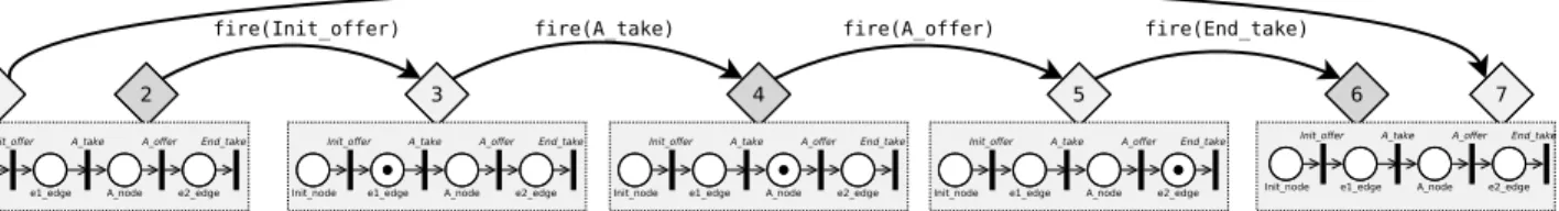
To illustrate how our architecture unfolds, we present the execution of the activity introduced at the top of Figure 8, which is compiled into the Petri net shown at the bottom.
Figure 11 shows the execution traces resulting from the execution. At the top, the execution of the target Petri net is shown. It directly results from the application of the inter-pretation rules introduced in Figure 1, which means that the execution is enclosed in a run(Net) step, which itself contains a sequence of fire(Transition) steps for eachTransition. Note that this Petri net execution is completely hidden from the runtime services connected to the feedback engine.
At the bottom, the execution of the source activity is shown, which directly results from the use of the example feedback manager presented in Section IV-D. This trace reflects the execution that can be observed by runtime services connected to the feedback engine. The step executeActivity(activity) cor-responds to the target step run(net) according to the definition of the processTargetStepStart and processTargetStepEnd oper-ations (see Algorithm 2 lines 2–5, and Algorithm 3 lines 2–3). Each offer(Node) step corresponds to a target fire(Transition) if this target step concerns aTransitionrepresenting the outgoing edge of an activity Node (see Algorithm 2 lines 14–17, and Algorithm 3 lines 12–13). Similarly, each step take(Node) corresponds to a target step fire(Transition) if it concerns a
Transitionrepresenting the incoming edge of an activity Node
(see Algorithm 2 lines 11–13, and Algorithm 3 lines 8–9). In addition, an executeNode(Node) encloses the offer(Node) and take(Node) steps of each Node(see Algorithm 2 lines 12 and 16, and Algorithm 3 lines 11 and 14).
fire(A_take) 1 2 run(net) 3 fire(Init_offer) fire(A_offer) 4 fire(End_take) 5 6 7 Init_node
Init_offer A_take A_offer End_take
e1_edge A_node e2_edge Init_node
Init_offer A_take A_offer End_take
e1_edge A_node e2_edge Init_node
Init_offer A_take A_offer End_take
e1_edge A_node e2_edge Init_node
Init_offer A_take A_offer End_take
e1_edge A_node e2_edge Init_node
Init_offer A_take A_offer End_take
e1_edge A_node e2_edge
(a) Target Petri net execution trace. This execution is hidden from runtime services connected to the activity diagram execution.
take(A) executeNode(Init)
I II.1 II.2 III.2 III.3 V.1
executeActivity(activity) executeNode(A) III.1 offer(Init) offer(A) IV V.2 VI.1 executeNode(End) take(End) V.3 VI.2 VII e1 e2 Init End A e1 e2 Init End A e1 e2 Init End A e1 e2 Init End A e1 e2 Init End A
(b) Source activity diagram execution trace, obtained using the feedback manager, based on the Petri net execution shown above. This shows what can be observed by runtime services connected to the activity diagram execution, i.e., at the source domain level.
Figure 11: Execution traces resulting from the execution of the models shown in Figure 8, after connecting the feedback manager of the activity diagram DSL to the Petri net interpreter. Refer to Figure 2 for the legend.
G. Implementation
We have implemented common parts of the approach (e.g., the feedback engine) for the GEMOC Studio [24], an Eclipse package composed of a language workbench and a modeling workbench. The language workbench relies on Ecore for defining abstract syntaxes, and provides multiple languages (e.g., Kermeta [16], xMOF [9], etc.) for defining operational semantics. The modeling workbench is an environment for creating, executing and debugging models, and provides one execution engine per supported kind of operational semantics. Originally, the GEMOC Studio focused on providing facil-ities to design and implement interpreted DSLs. Hence, our approach is the first attempt to support compiled DSLs in the GEMOC Studio. The source code is available on Github2and consists in Eclipse plugins written in Xtend and Java.
V. EVALUATION
We considered the following research questions, each matching one of the challenges stated in the introduction: RQ#1: Given an interpreted DSL and a compiled DSL with
trace-equivalent semantics, does the approach make it possi-ble to observe the same traces with both DSLs?
RQ#2: Does the approach enable the use of runtime ser-vices at the domain-level of compiled DSLs? In particu-lar, (2.1) Can different sorts of runtime services be used? (2.2) Can the same runtime services be shared across both interpreted and compiled DSLs?
RQ#3: What is the time overhead when executing compiled models with feedback management? In particular, how does it compare to: (3.1) executing without feedback management? (3.2) executing with an interpreter?
2https://github.com/tetrabox/gemoc-compilation-engine
A. Setup
Using the implementation presented in Section IV-G, the evaluation was made using the GEMOC Studio. We used this environment both for implementing the required DSLs and for executing the models. All material used for the evaluation can be found in the repository2. We describe the artifacts below.
1) Languages: Our evaluation relies on two different com-piled DSLs: the fUML subset presented throughout the paper using Petri nets as a target language, and a subset of UML state machines implemented as a standalone DSL using a subset of Java as a target language. We reimplemented a subset of Java as MiniJava in order to have a metamodel-based object-oriented programming language that fits the requirements of our approach, and that can be used for transforming UML state machines into Java following the state design pattern.
Below we first describe common points between both stud-ied DSLs. We then describe in more detail the UML state machines DSL, while we do not describe the fUML activity diagram DSL as it was already presented in the paper.
a) Common points: The fUML activity diagram DSL and the UML state machine diagram DSL were both defined in two flavors: one compiled version, and one interpreted version. Both share the same abstract syntax defined using Ecore. For the compiled versions, both the compiler and the feedback manager were defined using Xtend. All interpreters were de-fined using Kermeta [16]. The semantics of the interpreted and of the compiled versions are designed to be trace-equivalent.
b) UML state machines compiled DSL: For the second compiled DSL, we considered a subset of UML state machines where a conforming model contains a single StateMachine
with a single Region, which contains one initial State, one
FinalStateand arbitrary many regularStateelements. All nodes are connected using Transition elements, each with at least
s1 e1 init fin e2 e1 interfaceState{ publicState e1(); publicState e2(); }
classinitimplementsState{
publicState e1() { return news1(); } publicState e2() { return this; } }
classs1implementsState{
publicState e1() {
return news1();
}
publicState e2() {
return newfin();
} }
classfinimplementsState{
publicState e1() { return null; } publicState e2() { return null; }} classStateMachine{
publicState current;
publicStateMachine() {
this.current=newinit(); }
public voidhandle(String eventName) {
if(this.current!=null) { if(eventName.equals("e1")) {
this.e1();
}
else{
if(eventName.equals("e2")) {
this.e2(); } else{}} } } voide1() {
this.current=this.current.e1(); }
voide2() {
this.current=this.current.e2(); }
}
classMain{
public static voidmain(String[]args) {
StateMachine m=newStateMachine(); for(inti=0;i<args.length;i=i+1) {
String eventName=args[i]; m.handle(eventName) ; }
} }
Figure 12: Example of a source UML state machine, and its associated target MiniJava program obtained after compilation.
one Trigger referencing an Event, without any guards. The target language is an interpreted DSL called MiniJava that was inspired by an educational language of the same name3 that we made available on GitHub4. It supports a subset of Java that includes classes, interfaces, methods, a subset of primitive types, and a subset of expressions. The Xtext textual concrete syntax is identical to Java, and a MiniJava program is always a valid Java program that compiles and runs with the same behavior. The UML state machine compiler we developed is based on the well-known state design pattern from Gamma et al. [25], which describes how to implement a state machine as an object-oriented program. Figure 12 shows an example of a source UML state machine model and the target MiniJava program resulting from its compilation. We applied our architecture and wrote a definition of states, a definition of steps, and a feedback manager for MiniJava.
2) Runtime Services and Tracing: To answer RQ #2, we considered two runtime services provided in the GEMOC Studio: a trace constructor (described in [7]) and an omni-scient debugger (described in [22]). While these services were originally designed for interpreted DSLs, our approach makes compiled DSLs seemingly indistinguishable from interpreted DSLs. Hence, our experiment consists in reusing these services with compiled DSLs without changing a line of their code.
3) Models: To answer RQ #1 and RQ #3, which require executing models, we have implemented both a random activ-ity diagram generator and a random state machine generator. Both generators are parameterized by a fixed amount of nodes to create, and always create valid models where the final node of the model can be reached. We generated 30 UML state
3http://www.cambridge.org/resources/052182060X/ 4https://github.com/tetrabox/minijava
machines with sizes ranging from 10 to 100 states, and 3 scenarios per state machine, thus for a total of 90 different combinations of {UML state machine, scenario}.
B. Conducted Experiments and Results
a) RQ #1 (same observations): We have executed each of the 130 generated models with both the interpreted and the compiled versions of both executable DSLs, and captured one domain-level trace per execution. For compiled DSLs, the feedback manager was used for domain-level observation to construct traces. We automatically compared each trace from an interpreted execution with the corresponding trace from a compiled execution, and did not find any differences.
To summarize and answer RQ #1, the approach makes it possible to observe the exact same executions with both interpreted and compiled versions of a DSL.
b) RQ #2 (runtime services): We were able to use both the trace constructor and the omniscient debugger with both the interpreted and compiled versions of each considered DSL, without changing a single line of the services’ code. For example, when the omniscient debugger is used with the activity diagram DSL, it is able to pause on a breakpoint defined in the activity, to show the active node, to display a view of all domain-level variables (i.e., the held tokens), and to display a stack of ongoing domain-level execution steps. The underlying executed Petri net is invisible to the modeler. To summarize and answer RQ #2, the approach does enable the use of different sorts of runtime services, which can be shared among both interpreted and compiled DSLs.
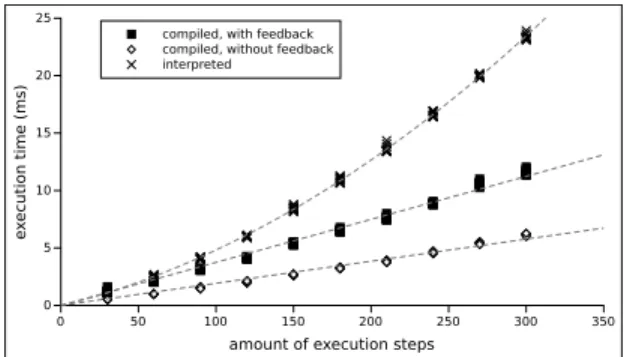
c) RQ #3 (overhead): Using Java’s System.nanotime, we measured the duration when executing each of the models of each of the DSLs using: (1) the compiled version of the DSL with the feedback manager; (2) the compiled version of the DSL without the feedback manager; (3) the interpreted version of the DSL. Each execution was done 25 times, starting with 14 warmups (i.e., without measuring). The retained value is then the median of the remaining 11 measured durations.
Figure 13a shows the collected results for the fUML activity diagram DSL. We observe that the fastest executions are the ones from the compiled version of the DSL without the feedback manager, i.e., from the Petri net interpreter alone. When adding the feedback manager, the execution time is on average multiplied by 2, i.e., the execution takes twice the time. In both cases, the execution times seem to grow linearly with the number of execution steps. The interpreted version of the DSL is on average 1,6 times slower compared to the compiled DSL without feedback management.
Figure 13b shows the results for the UML state machines DSL. Here we observe that the interpreted version of the DSL is the fastest, which is explained by lack of optimizations within the MiniJava interpreter, which makes the compiled version much slower. When using the feedback manager with the compiled version, the execution time is on average only multiplied by 1,01, i.e., the execution time is increased by 1%. To summarize and answer RQ #3, we observe that when using a feedback manager with a compiled DSL, execution
0 50 100 150 200 250 300 350 amount of execution steps
0 5 10 15 20 25 e xecution time (ms)
compiled, with feedback compiled, without feedback interpreted
(a) fUML activity diagram DSL, compiled to Petri nets.
0 200 400 600 800 1000 1200
amount of execution steps
0 100 200 300 400 500 600 700 e xecution time (ms)
compiled, with feedback compiled, without feedback interpreted
(b) UML state machines DSL, compiled to MiniJava.
Figure 13: Execution times in three cases: compiled with feedback, compiled without feedback, and interpreted.
times are multiplied by 1,01 with UML state machines, and by 2 with fUML activity diagrams. If we consider the overhead categorizations proposed by Maplesden etal. [26], these two numbers respectively match the “Very Low over-head” category, and the lowest bound of the “High overover-head” category. While we consider these slowdowns acceptable— only a few milliseconds of absolute overhead in average in both cases—this discrepancy suggests that the overhead may not be inherent to the architecture itself, and may instead be dependent on how the feedback manager is implemented. C. Threats to Validity
First, the evaluation was made using only two compiled DSLs, thus it does not show whether similar results would be obtained with yet another different compiled DSL. To mitigate this problem, we chose cases with very different target DSLs, hence with very different semantic gaps between source and target languages. Applying the architecture on more cases is one of the ongoing next steps of our work. Second, as we already mentioned, the comparison of execution times between the interpreted and compiled versions of the considered DSLs may not be fair due to discrepancies in the optimizations of the source or target interpreters. For this reason, we did not include these results as part of the answer given to the research question, and only provide them as an interesting observation. Lastly, we considered generated models instead of models from a real world source. This is partly compensated by the considerable amount of models we generated.
VI. RELATEDWORK
a) Back-tracing verification results: When the transla-tional semantics of a DSL are defined to target a formal language with model checking tool-support, counter-examples produced by the model checker are not expressed with the DSL concepts. Hence, many back-tracing approaches aim at translating such counter-examples back to the source domain [27]–[30]. However, these techniques focus on translating back execution traces obtained after execution (e.g., counter-examples given by analysis tools), while our approach provides observation and control during the execution,
b) Monitoring and debugging for compiled DSLs: Sev-eral approaches aim at supporting domain-level debugging or monitoring for compiled DSLs, which always imply some form of observation or control over the execution. Wu et al. [31] propose a generative approach focusing on grammar-based compiled DSLs, where the lines of the source program are mapped to the lines of the target program, in order to map domain-level debugging actions to the existing target debugger. Still for grammar-based compiled DSLs, Lindeman et al. [32] proposes a similar approach were the source DSL program is instrumented with debug information. In the context of extensible languages, Pavletic et al. [33] proposes a framework to define and extend debuggers. Das et al. [34] describe a framework to monitor at the domain-level the execution of models that were compiled to code, with a strong focus on UML-RT. Yet, all these approaches focus on specific runtime services, while our approach aim to lay the foundations for defining and using of any kind of runtime service for metamodel-based compiled DSLs.
VII. CONCLUSION ANDFUTUREWORK
Observing and controlling the execution of models con-forming to a compiled DSL is a difficult task, due to the semantic gap between the considered source and target lan-guages. We addressed this problem through a generic approach to provide feedback management for compiled DSLs. The direct perspectives of this work include: studying how the feedback manager materializes a weak bisimulation relation [27], [35] between the source and target languages; handling compiled DSLs defined through a code generator instead of a model transformation; providing an easier way to define the feedback manager (e.g., using a dedicated DSL, similarly to [36]); managing the stimuli sent to the source model during the execution, by translating them to stimuli for the target model; and measuring the amount of effort required to define a feedback manager as compared to defining an interpreter.
ACKNOWLEDGEMENT
This work is partially funded by the Austrian Science Fund (FWF) under the grant numbers P 30525-N31 and P 28519, by the Austrian Federal Ministry for Digital and Economic Affairs and the National Foundation for Research, Technology and Development, and by the French project ELOGE (Atlanstic 2020 Amorçage) financed by Région des Pays de la Loire.
REFERENCES
[1] Object Management Group, “Semantics of a Foundational Subset for Executable UML Models, V 1.1,” August 2013.
[2] R. Bendraou, B. Combemale, X. Crégut, and M. P. Gervais, “Definition of an executable SPEM 2.0,” in Proceedings of the 14th Asia-Pacific
Software Engineering Conference (APSEC’07). IEEE, 2007.
[3] D. Harel, H. Lachover, A. Naamad, A. Pnuelli, M. Politi, R. Sherman, A. Shtull-trauring, and M. Trakhtenbrot, “STATEMATE: a working environment for the development of complex reactive systems,” IEEE Transactions on software engineering, vol. 16, no. 4, pp. 403–414, 1990. [4] OASIS, “Web Services Business Process Execution Language Version 2.0,” 2007. [Online]. Available: https://docs.oasis-open.org/wsbpel/2.0/ OS/wsbpel-v2.0-OS.html
[5] E. Bousse, J. Corley, B. Combemale, J. Gray, and B. Baudry, “Sup-porting Efficient and Advanced Omniscient Debugging for xDSMLs,” in International Conference on Software Language Engineering (SLE). ACM, 2015.
[6] B. Meyers, J. Denil, I. Dávid, and H. Vangheluwe, “Automated testing support for reactive domain-specific modelling languages,” in International Conference on Software Language Engineering (SLE), 2016, pp. 181–194. [Online]. Available: http://dl.acm.org/citation.cfm? doid=2997364.2997367
[7] E. Bousse, T. Mayerhofer, B. Combemale, and B. Baudry, “Advanced and efficient execution trace management for executable domain-specific modeling languages,” Software & Systems Modeling, May 2017. [Online]. Available: http://dx.doi.org/10.1007/s10270-017-0598-5 [8] B. Combemale, X. Crégut, and M. Pantel, “A Design Pattern to Build Executable DSMLs and Associated V&V Tools,” in 19th Asia-Pacific Soft. Eng. Conf. (APSEC), vol. 1. IEEE, 2012.
[9] T. Mayerhofer, P. Langer, M. Wimmer, and G. Kappel, “xMOF: Exe-cutable DSMLs based on fUML,” in 6th Int. Conf. on Soft. Lang. Eng. (SLE), ser. LNCS, vol. 8225. Springer, 2013.
[10] G. Engels, J. H. Hausmann, R. Heckel, and S. Sauer, “Dynamic Meta-Modeling: A Graphical Approach to the Operational Semantics of Behavioral Diagrams in UML,” in Proceedings of the Third International Conference on the Unified Modeling Language (UML’00), ser. LNCS, vol. 1939. Springer Berlin Heidelberg, 2000, pp. 323–337.
[11] N. Bandener, C. Soltenborn, and G. Engels, “Extending DMM Behavior Specifications for Visual Execution and Debugging,” in Proceedings of the Third International Conference on Software Language Engineering (SLE’10), vol. 6563 LNCS. Springer Berlin Heidelberg, 2010. [12] J. Tatibouët, A. Cuccuru, S. Gérard, and F. Terrier, “Formalizing
Execution Semantics of UML Profiles with fUML Models,” in 17th Int. Conf. on Model Driven Eng. Lang. and Sys. (MODELS), ser. LNCS, vol. 8767. Springer, 2014.
[13] F. Ciccozzi, I. Malavolta, and B. Selic, “Execution of UML models: a systematic review of research and practice,” Software & Systems Modeling, Apr 2018. [Online]. Available: https://doi.org/10.1007/ s10270-018-0675-4
[14] Object Management Group, “Meta Object Facility (MOF) Core Specifi-cation, V 2.5,” Object Management Group, June 2016, http://www.omg. org/spec/MOF/2.5.
[15] D. Steinberg, F. Budinsky, M. Paternostro, and E. Merks, EMF: Eclipse Modeling Framework, 2nd Edition, ser. Eclipse Series. Addison-Wesley Professional, 2008.
[16] J.-M. Jézéquel, B. Combemale, O. Barais, M. Monperrus, and F. Fou-quet, “Mashup of metalanguages and its implementation in the Kermeta language workbench,” Software & Systems Modeling (SoSyM), vol. 14, no. 2, 2013.
[17] A. Hegedüs, I. Ráth, and D. Varró, “Replaying Execution Trace Models for Dynamic Modeling Languages,” Periodica Polytechnica - Electrical Engineering, vol. 56, no. 3, pp. 71–82, 2012.
[18] F. Jouault and I. Kurtev, “Transforming models with ATL,” in Proceed-ings of the Workshop on Model Transformations in Practice (MTiP’05), ser. LNCS, vol. 3844. Springer Berlin Heidelberg, 2006, pp. 128–138. [19] A. Yie and D. Wagelaar, “Advanced Traceability for ATL,” in 1st International Workshop on Model Transformation with ATL (MtATL’09, 2009.
[20] E. Syriani and H. Ergin, “Operational semantics of UML activity diagram: An application in project management,” in 2nd International Workshop on Model-Driven Requirements Engineering (MoDRE), Sept 2012, pp. 1–8.
[21] T. S. Staines, “Intuitive Mapping of UML 2 Activity Diagrams into Fundamental Modeling Concept Petri Net Diagrams and Colored Petri Nets,” in 15th International Conference and Workshop on the Engineer-ing of Computer Based Systems (ECBS), March 2008, pp. 191–200. [22] E. Bousse, D. Leroy, B. Combemale, M. Wimmer, and B. Baudry,
“Omniscient debugging for executable DSLs,” Journal of Systems and Software, vol. 137, pp. 261 – 288, 2018. [Online]. Available: http://www.sciencedirect.com/science/article/pii/S0164121217302765
[23] J. Deantoni, P. Issa Diallo, C. Teodorov, J. Champeau, and
B. Combemale, “Towards a Meta-Language for the Concurrency Concern in DSLs,” in Design, Automation and Test in Europe Conference and Exhibition (DATE), Grenoble, France, Mar. 2015. [Online]. Available: https://hal.inria.fr/hal-01087442
[24] E. Bousse, T. Degueule, D. Vojtisek, T. Mayerhofer, J. Deantoni, and B. Combemale, “Execution Framework of the GEMOC Studio (Tool Demo),” in Proceedings of the 2016 ACM SIGPLAN International Conference on Software Language Engineering, ser. SLE 2016, Amsterdam, Netherlands, Oct. 2016, p. 8. [Online]. Available: https://hal.inria.fr/hal-01355391
[25] E. Gamma, R. Helm, R. Johnson, and J. Vlissides, Design Patterns:
Elements of Reusable Object-oriented Software. Boston, MA, USA:
Addison-Wesley Longman Publishing Co., Inc., 1995.
[26] D. Maplesden, E. D. Tempero, J. G. Hosking, and J. C. Grundy, “Performance Analysis for Object-Oriented Software: A systematic mapping,” IEEE Trans. Software Eng., vol. 41, no. 7, pp. 691–710, 2015. [Online]. Available: https://doi.org/10.1109/TSE.2015.2396514 [27] B. Combemale, L. Gonnord, and V. Rusu, “A Generic Tool for Tracing
Executions Back to a DSML’s Operational Semantics,” in 7th European Conference on Modelling Foundations and Application (ECMFA), R. B. France, J. M. Kuester, B. Bordbar, and R. F. Paige, Eds. Berlin, Heidelberg: Springer Berlin Heidelberg, 2011, pp. 35–51. [Online]. Available: http://dx.doi.org/10.1007/978-3-642-21470-7_4
[28] F. Zalila, X. Crégut, and M. Pantel, “Formal Verification Integration Approach for DSML,” in 16th International Conference on
Model-Driven Engineering Languages and Systems (MODELS). Berlin,
Heidelberg: Springer Berlin Heidelberg, 2013, pp. 336–351. [Online]. Available: http://dx.doi.org/10.1007/978-3-642-41533-3_21
[29] Á. Hegedüs, G. Bergmann, I. Ráth, and D. Varró, “Back-annotation of Simulation Traces with Change-Driven Model Transformations,” in Pro-ceedings of the 8th International Conference on Software Engineering
and Formal Methods (SEFM’10). IEEE, 2010, pp. 145–155.
[30] W. Haberl, M. Herrmannsdoerfer, J. Birke, and U. Baumgarten, “Model-Level Debugging of Embedded Real-Time Systems,” in 10th Interna-tional Conference on Computer and Information Technology, June 2010. [31] H. Wu, J. Gray, and M. Mernik, “Grammar-driven Generation of Domain-specific Language Debuggers,” Software: Practice and Experience, vol. 38, no. 10, pp. 1073–1103, Aug. 2008. [Online]. Available: http://dx.doi.org/10.1002/spe.v38:10
[32] R. T. Lindeman, L. C. Kats, and E. Visser, “Declaratively
Defining Domain-specific Language Debuggers,” in 10th International Conference on Generative Programming and Component Engineering
(GPCE), ser. GPCE ’11. New York, NY, USA: ACM, 2011, pp. 127–
136. [Online]. Available: http://doi.acm.org/10.1145/2047862.2047885 [33] D. Pavletic, M. Voelter, S. A. Raza, B. Kolb, and T. Kehrer,
“Extensible Debugger Framework for Extensible Languages,” in 20th Ada-Europe International Conference on Reliable Software
Technologies, J. A. de la Puente and T. Vardanega, Eds. Cham:
Springer International Publishing, 2015, pp. 33–49. [Online]. Available: http://dx.doi.org/10.1007/978-3-319-19584-1_3
[34] N. Das, S. Ganesan, L. Jweda, M. Bagherzadeh, N. Hili, and J. Dingel, “Supporting the Model-driven Development of Real-time Embedded Systems with Run-time Monitoring and Animation via Highly Customizable Code Generation,” in 19th International Conference on Model Driven Engineering Languages and Systems (MODELS). New York, NY, USA: ACM, 2016, pp. 36–43. [Online]. Available: http://doi.acm.org/10.1145/2976767.2976781
[35] B. Combemale, X. Crégut, P.-L. Garoche, and X. Thirioux, “Essay on Semantics Definition in MDE - An Instrumented Approach for Model Verification,” Journal of Soft., vol. 4, no. 9, pp. 943–958, 2009. [36] F. Zalila, X. Crégut, and M. Pantel, “A DSL to Feedback Formal
Verification Results,” in 13th Workshop on Model-Driven Engineering,