HAL Id: tel-02089176
https://tel.archives-ouvertes.fr/tel-02089176
Submitted on 3 Apr 2019HAL is a multi-disciplinary open access archive for the deposit and dissemination of sci-entific research documents, whether they are pub-lished or not. The documents may come from teaching and research institutions in France or abroad, or from public or private research centers.
L’archive ouverte pluridisciplinaire HAL, est destinée au dépôt et à la diffusion de documents scientifiques de niveau recherche, publiés ou non, émanant des établissements d’enseignement et de recherche français ou étrangers, des laboratoires publics ou privés.
Towards hardware synthesis of a flexible radio from a
high-level language
Mai-Thanh Tran
To cite this version:
Mai-Thanh Tran. Towards hardware synthesis of a flexible radio from a high-level language. Network-ing and Internet Architecture [cs.NI]. Université Rennes 1, 2018. English. �NNT : 2018REN1S072�. �tel-02089176�
Towards Hardware Synthesis of a Flexible Radio
from a High-Level Language
Thèse présentée et soutenue à Lannion, le 13 novembre 2018
Unité de recherche : IRISA (UMR 6074), Institut de Recherche en Informatique et Systèmes Aléatoires, École Nationale Supérieure des Sciences Appliquées et de Technologies
Thèse N° : RENNI 13903563
T
HESE DE DOCTORAT DE MAI
-
THANH TRAN
L'UNIVERSITE
DE
RENNES
1
C
OMUEU
NIVERSITEB
RETAGNEL
OIREECOLE DOCTORALE N°601
Mathématiques et Sciences et Technologies de l'Information et de la Communication
Spécialité : Informatique
Rapporteurs avant soutenance :
Lillian BOSSUET, Professeur des Universités, Université Jean Monnet, Saint-Etienne Guillaume VILLEMAUD, Maître de Conférences HDR, INSA Lyon
Composition du Jury :
Président : Christophe JEGO, Professeur des Universités, ENSEIRB-MATMECA Bordeaux Examinateurs : Lillian BOSSUET, Professeur des Universités, Université Jean Monnet, Saint-Etienne
Sylvie KEROUEDAN, Maître de Conférences HDR, IMT Atlantique Guillaume VILLEMAUD, Maître de Conférences HDR, INSA Lyon
Dir. de thèse : Emmanuel CASSEAU, Professeur des Universités, Université de Rennes 1 Co-enc. de thèse : Matthieu GAUTIER, Maître de Conférences, Université de Rennes 1
Par
3
Table of Contents
Chapter 1.
Introduction ... 13
1.1. 5G, Internet of Things (IoT) and Software-Defined Radio (SDR)... 14
1.2. Proposed Methodology and Main Contributions ... 16
1.3. Outline... 16
Part I - BACKGROUND ... 19
Chapter 2.
Flexible Radio and Software-Defined Radio ... 21
2.1. Introduction ... 22
2.2. Digital Radio System ... 22
2.2.1. Symbol Mapping ... 23
2.2.2. Channel Access ... 25
2.3. Flexible Radio ... 26
2.3.1. Cognitive Radio ... 27
2.3.2. Introduction to Software-Defined Radio Architecture ... 28
2.4. Waveform of Interest: The 3GPP-LTE Standard ... 29
2.4.1. The 3GPP-LTE Physical Layer ... 30
2.4.2. Fast Fourier Transform ... 33
2.5. Software –Defined Radio (SDR) Platforms ... 35
2.5.1. General Purpose Processor (GPP) Approach ... 35
2.5.2. Co-processor Approach ... 36 2.5.3. Multiprocessor Approach ... 37 2.5.4. FPGA Approach ... 38 2.6. FPGA-based SDRs ... 39 2.6.1. Multi-waveform Configuration ... 39 2.6.2. Separated Configurations ... 40 2.6.3. Partial Reconfiguration ... 40 2.7. Conclusions ... 41
Chapter 3.
High Level Synthesis and Hardware Reconfiguration on FPGAs . 43
4
3.1. Introduction ... 44
3.2. High Level Synthesis ... 44
3.2.1. HLS Fundamental ... 44
3.2.2. Advantages of HLS ... 46
3.2.3. HLS Tools ... 47
3.3. Hardware reconfiguration on FPGAs ... 53
3.3.1. Introduction ... 53
3.3.2. Dynamic Partial Reconfiguration ... 56
3.4. Conclusions ... 58
Part II - CONTRIBUTION ... 61
Chapter 4.
Design Flow for Flexible Radio on FPGA-based SDRs ... 63
4.1. Introduction ... 64
4.2. Reconfiguration Methods for Software Defined Reconfiguration ... 64
4.2.1. Software Reconfiguration ... 64
4.2.2. Hardware Reconfiguration ... 65
4.2.3. Algorithmic Reconfiguration ... 66
4.3. Proposed Design Flow and System Architecture for Flexible Radio on FPGA s ... 66
4.3.1. System Architecture for Flexible Radio on FPGA s ... 67
4.3.2. Design Flow for Flexible Radio on FPGAs ... 69
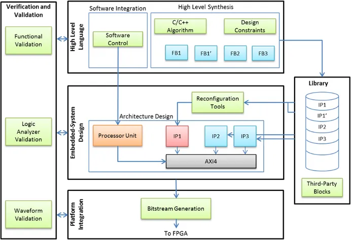
4.3.3. Verification and Validation ... 70
4.4. Conclusions ... 73
Chapter 5.
Design and Exploration of a Flexible FFT for LTE standard ... 75
5.1. Introduction ... 76
5.2. Radix-2 DIT FFT/IFFT in Vivado HLS ... 76
5.2.1. C code re-writing for Vivado HLS ... 78
5.2.2. Fixed-point FFT/IFFT in Vivado HLS ... 79
5.2.3. Conclusions ... 82
5.3. Reconfigurable Blocks ... 83
5.3.1. Software Reconfigurable Block ... 83
5.3.2. Hardware Reconfigurable Block ... 84
5
5.4. Latency Estimation ... 86
5.4.1. Computing an Estimate of The Latency ... 87
5.4.2. Experiment and Results for Latency Formula ... 88
5.5. Design Space Exploration in the Power-Of-Two Point FFT ... 90
5.5.1. DSE at Clock Frequency of 100 MHz ... 90
5.5.2. DSE at Other Clock Frequencies ... 93
5.5.3. Comparisons and Conclusions ... 94
5.6. Conclusions ... 97
Chapter 6.
Designing a flexible FFT for LTE standard as a use case ... 99
6.1. Introduction ... 100
6.2. Proposed Flexible FFT Implementations for LTE Standard ... 100
6.2.1. Generator ... 101
6.2.2. X-QAM Modulator ... 101
6.2.3. Implementation for Software Reconfiguration... 102
6.2.4. Implementation for Hardware Reconfiguration ... 102
6.3. Results of the Proposed Flexible FFT Implementation ... 103
6.3.1. Implementation for Software Reconfiguration. ... 103
6.3.2. Implementation for Hardware Reconfiguration. ... 104
6.3.3. Comparisons ... 104
6.4. Demonstration of the FFT Implementation for LTE Standard ... 105
6.4.1. Testbed Description ... 105
6.4.2. Virtex 6 ML 605 Evaluation Board ... 106
6.4.3. Required Software Development Tools ... 106
6.4.4. Experiments ... 107
6.5. Conclusions ... 107
Chapter 7.
Conclusions and Perspectives ... 111
Publication ... 117
6
List of Figures
Figure 2.1 Digital radio system... 22
Figure 2.2 OSI model. ... 23
Figure 2.3 The constellations for BPSK, QPSK and 16-QAM. ... 24
Figure 2.4 The cognitive radio’s cognition cycle. ... 27
Figure 2.5 Basic software-controlled radio. ... 28
Figure 2.6 Ideal software-defined radio: (a) transmitter, (b) receiver. ... 29
Figure 2.7 Realistic software-defined radio: (a) transmitter, (b) receiver. ... 29
Figure 2.8 LTE generic frame structure (Zyren and McCoy 2007). ... 30
Figure 2.9 Physical layer coding rate as a function of channel conditions and modulation scheme (Johnson 2012). ... 32
Figure 2.10 A basic SC-FDMA transmitter and receiver (Zyren and McCoy 2007). ... 32
Figure 2.11 An eight-point DFT, divided in four two-point DFTs with bit reversal on inputs (Jones 2006 ). ... 34
Figure 2.12 Multi-processor approach. ... 37
Figure 2.13 FPGA-based approach. ... 38
Figure 2.14 Separated configurations. ... 40
Figure 2.15 Partial reconfiguration. ... 41
Figure 3.1 Generic HLS design flow. ... 45
Figure 3.2 The Vivado HLS design flow. ... 50
Figure 3.3 RTL hierarchy after HLS synthesis. ... 50
Figure 3.4 Dataflow optimization (Xilinx 2016). ... 51
Figure 3.5 Pipeline optimization (Xilinx 2016). ... 51
Figure 3.6 Unrolled optimization example. ... 52
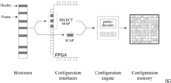
Figure 3.7 The reconfiguration chain for a Virtex FPGA. ... 54
Figure 3.8 Configuration uses 1 address dimension (left) and 2 address dimensions (right) (Bolchini, Miele and Sandionigi 2011). ... 54
Figure 3.9 Two methods of delivering a partial bit file (with Xilinx devices) (Dye 2012). ... 56
Figure 3.10 Partial reconfiguration software flow (Xilinx 2016). ... 57
Figure 4.1 Design approach based on hardware reconfiguration. ... 65
Figure 4.2 Tradeoff between resources and reconfiguration time for the different reconfigurations. ... 66
Figure 4.3 HLS-based design flow for a reconfigurable module using Software-Defined Reconfiguration. ... 67
Figure 4.4 System architecture for FPGA-based SDR. ... 68
Figure 4.5 Proposed design flow for Flexible Radio using FPGA-based SDR... 69
Figure 4.6 Step-by-step development flow using Xilinx tools. ... 70
Figure 4.7 Verification and validation tools for the flexible radio design flow. ... 71
Figure 4.8 Example of code level verification in Vivado HLS based on a Matlab-provided reference. ... 71
7
Figure 4.10 Example of RF signal analysis: an OFDM-based RF spectrum. ... 73
Figure 5.1 Virtex-6 FPGA DSP48E1 Slice (Xilinx 2011) ... 81
Figure 5.2 Structure of the 1536-point FFT ... 86
Figure 5.3 The chronogram of the different steps of Algorithm 5. ... 87
Figure 5.4 FFT latency with unrolling factor U = 1 a) FFT 2048; b) FFT 128. ... 89
Figure 5.5 The latency vs number of DSP slices (S is for Simulation after synthesis and F is for the Formula estimate) (frequency = 100 MHz). ... 91
Figure 5.6 Timing chronogram of the third loop based on Algorithm 6. ... 92
Figure 5.7 Timing chronogram of the third loop based on Algorithm 7: a) U = 4; b) U = 8. ... 93
Figure 5.8 Latency vs number of DSPs for clock frequencies 200Mhz (left) and 500MHz (right). ... 93
Figure 5.9 Latency vs number of DSPs at frequency 50MHz. ... 94
Figure 5.10 The third loop computation time vs clock frequency for U = 1 (= time to compute a radix-2 FFT) ... 95
Figure 5.11 Time to compute 1 FFT vs clock frequency, U = 1 ... 95
Figure 5.12 The third loop computation time vs clock frequency for U = 4 ... 96
Figure 5.13 Timing chronogram of the third loop at 50 MHz: a) U = 1; b) U = 4. ... 96
Figure 5.14 Time to compute 1 FFT vs frequency, U = 4 ... 97
Figure 6.1 Overview of the architecture of the multi-mode FFT. ... 100
Figure 6.2 The 64-QAM constellation with ChipScope Pro. ... 101
Figure 6.3 The architecture of the multi-mode FFT with software reconfiguration. ... 102
Figure 6.4 The architecture of the multi-mode FFT with hardware reconfiguration. ... 103
Figure 6.5 The testbed description. ... 105
Figure 6.6 The demonstration platform. ... 106
8
List of Tables
Table 2.1 Downlink OFDM modulation parameters ... 31
Table 2.2 A comparative study between different approaches for SDR. ... 39
Table 3.1 General information about HLS tools. ... 49
Table 3.2 Maximum bandwidths for configuration ports with Virtex architectures. ... 56
Table 5.1 Resources required (after synthesis) for a radix_2 block for different input data lengths. ... 81
Table 5.2 Output errors with different data lengths. ... 82
Table 5.3 Software reconfiguration synthesis results for a FFT with 2 modes (128/2048). ... 83
Table 5.4 Hardware reconfiguration synthesis results for a FFT with 2 modes (128/2048). ... 85
Table 5.5 The latency of loop number 3 depending on unrolling factor ... 89
Table 5.6 Estimated latency and latency obtained by simulation after HLS. ... 90
Table 6.1 Performance of the multimode FFT for LTE standard with software reconfiguration ... 104
9
List of algorithms
Algorithm 1 Software reconfiguration for the automatic generation of a multi-mode processing block..59 Algorithm 2 C program for the radix-2 DIT FFT……… …..71 Algorithm 3 Sine lookup table based code………..……..72 Algorithm 4 Two point FFT code………...73 Algorithm 5 Overview of the algorithmic reconfiguration based code for the power-of-two point FFT….79 Algorithm 6 Shortcut of the third loop in the FFT………..84 Algorithm 7 Shortcut of the updated third loop in FFT………..85
10
Acronyms and Abbreviations
ADC Analog-to-Digital Conversion
ARM Advanced RISC Machines
ASIC Application Specific Integrated Circuits
ASK Amplitude-shift keying
AWGN Additive White Gaussian Noise
AXI Advanced Extensible Interface
BER Bit Error Rate
CDMA Code Division Multiple Access
CLB Configurable Logic Block
CP Cyclic Prefix
CR Cognitive Radio
DFT Digital Fourier Transform
DIT Decimation In Time
DPR Dynamic Partial Reconfiguration
DSE Design Space Exploration
DSL Domain Specific Languages
DSP Digital Signal Processor
FDMA Frequency Division Multiple Access FFT Fast Fourier Transform
FPGA Field Programmable Gate Arrays FSK Frequency-shift keying
GPL General-purpose Programmable Language
GPP General Purpose Processor
GPU Graphics Processing Unit
HDL Hardware Description Language
HLL High Level Language
HLS High Level Synthesis
ICI Inter-Carrier Interferences
ICT Information and Communications Technologies IDFT Inverse Digital Fourier Transform
IoT Internet of Things
LB Logic Blocks
LTE Long-Term Evolution
LUT Look Up Table
NoC Network on Chip
OFDM Orthogonal Frequency Division Multiplexing OFDM Orthogonal Frequency-Division Multiple Access
OSI Open Systems Interconnection
11
PER Packet Error Rate
PHY Physical Layer
PLB Processor Local Bus
PRB Physical Resource Block
PSK Phase-shift keying
QPSK Quadrature Phase Shift Keying
RAM Random Access Memories
RF Radio Frequency
RTL Register-Transfer Level
SC-FDMA Single-Carrier Frequency Division Multiple Access
SDK Software Development Kit
SDR Software-Defined Radio TDMA Time Division Multiple Access VLIW Very Large Instruction Word
13
14
1.1. 5G, Internet of Things (IoT) and Software-Defined Radio (SDR)
Wireless communication devices have been developed and raised rapidly last 20 years. They have completely changed modern lifestyle, enabling modern societies to operate more efficiently, and had a major impact on modern politics, economy, education, health, entertainment, logistics, travel and industry among others. Wireless communication enables the connection of people for content exchange, be it data and/or multimedia. The fifth generation of wireless communication, namely the 5G, addresses a new kind of users. In addition to connect people each other, the next breakthrough is the connectivity of machines with other machines, referred to as “M2M”, which is the basis of the Internet of Things (IoT) paradigm [1] [2]. IoT refers to an Internet-like network, in which millions of embedded devices are connected together. These devices are various, and range from simple RFID tags to powerful smartphones. All of them are connected to wireless links more or less without any predefined infrastructures or communication standards. This network is opening an extreme breakthrough in the way people interact with traditional objects. Therefore, in addition to a massive increase in the number of accesses and throughput constraints, 5G standard has to take into account new requirements.
First, the use of M2M for virtual reality or human-to-machine interaction rely on steering/control communications with a cloud infrastructure. Hence, the required latency of such communications must be low enough to enable a round-trip delay from devices through the network back to devices of approximately 1ms [3]. As a comparison, LTE frame duration is about 5 or 10 ms.
In addition to the latency requirements, reducing energy consumption is an on-going major challenge for two reasons: the first one is the total energy consumption of ICT (Information and Communications Technologies) infrastructure that must be reduced; the second one is the duration of the activity time of the devices (e.g. Wireless Sensor Network nodes, IoT devices, etc.) that must significantly increase to be massively deployed and used.
The last requirement we want to highlight is the flexibility the devices must provide to satisfy the number of modes related to the different communication standards. Indeed, in order to meet the time and space fluctuations of a service, in order to make several classes of objects be connected together and in order to answer the spectrum scarcity issue, it is expected that the new generation of wireless communications should be able to change their own features in real time.
Hence, a new 5G standard is needed to tackle these challenges (throughput, latency, energy consumption and flexibility). Focusing on the baseband processing of the physical layer, two main issues are raised by these new requirements: (#i) what are the signal processing techniques that could help improving the quality of the link, spectrum usage and energy efficiency? (#ii) what kind of hardware could associate flexibility, energy efficiency and high-performance computing of these signal processing techniques?
A huge effort is currently spent on proposing new physical layers and many digital communication techniques have been widely studied to tackle issue (#i) such as the Cognitive Radio (CR) [4], the Cooperative Radio [5] or the Green Radio [6]. However, few studies address issue (#ii). The goal of this PhD thesis is to study new architectures for the implementation of such innovations as well as new
15
design methodologies. To this aim, two contradictory issues must be faced. The first one is the flexibility required, with the important number of modes for a single protocol and the number of protocols to be supported by a single device. The second concern is related to performance and power consumption requirements.
In the past, radio engineers used to focus on implementing and optimizing a single communication protocol (or waveform) at a time. Application Specific Integrated Circuits (ASICs) were most of the time used because theses circuits allow both high throughput and low power consumption. However, this kind of circuits is not flexible and requires the application to be described at Register-Transfer Level (RTL) using a Hardware Description Language (HDL) such as VHDL or Verilog, which is quite a tough task. This approach is quite obsolete while current radio devices must be flexible i.e. must be able to reconfigure their protocol among different numbers of modes for a given waveform or among different waveforms. A promising technology, which can bring these needs into practice, is SDR [4] [7] [8]. SDR allows the fast prototyping of a waveform from its high-level description, specified in C/C++ for instance, on a hardware device that can be reconfigured. Unlike other approaches that use a dedicated hardware for a waveform, SDR concept relies on a single software-based technology such as microprocessors, which can be reprogrammed to implement signal processing for all possible waveforms. The SDR device is controlled by a software program and can be easily configured at different levels: from simple processing blocks to full waveforms whenever necessary. However, in practice, if this approach is clearly more flexible than earlier ones and allows fast prototyping, it also usually decreases performance and increases power consumption.
An interesting trade-off between performance and power consumption could be achieved using Field Programmable Gate Arrays (FPGAs) circuits. FPGAs enable the design of customized circuit architectures through a configuration file. It can be reprogrammed using other configuration files to implement different functionalities. FPGA-based SDR is an old paradigm [9] offering in theory a good tradeoff between flexibility and processing power. The programmability of such platform is however a bottleneck as FPGAs need a HDL description as an entry in the design flow.
This PhD aims at improving the programmability of FPGA-based SDR through the use of high-level specifications instead of HDL ones. Fast prototyping capability is achieved by leveraging High-Level Synthesis (HLS) techniques and related tools to generate RTL descriptions from high-level specifications [10] [11]. If HLS fast prototyping capability enables the compile-time flexibility of a FPGA-based SDR, run-time flexibility is still an open issue. This thesis addresses consequently the FPGA-based implementation of a run-time hardware reconfiguration of a flexible waveform from its high-level description. The proposed methodology mainly aims at analyzing the performance of using a multi-mode processing block with control signals or Dynamic Partial Reconfiguration (DPR) to provide in both cases flexibility.
16
1.2. Proposed Methodology and Main Contributions
The proposed methodology is a guideline to completely build a flexible radio on FPGA-based SDR, which can be reconfigured at run-time. The flow goes from the description of the waveform to the implementation, verification and validation steps of the system. Its entry is a description with a high-level language that leverages HLS techniques to build a radio system. Two kinds of approaches are used to address the run-time flexibility of a FPGA- based SDR. The first one proposes to automatically design multi-mode RTL components with control signals to switch between the different modes (similar to [12] ). The other approach is based on dynamic partial reconfiguration (DPR). Run-time DPR, referred to as
Hardware reconfiguration in the following of this PhD report, is the ability to reconfigure a part (or
parts) of the FPGA (e.g. a functionality at the hardware level) while the rest of the FPGA continues to work. It has been a research topic since the 90s [13] and it can be currently used in FPGAs, since Xilinx and Altera companies promote such technology [2] [5]. The main advantage of the hardware reconfiguration is to provide both hardware flexibility and hardware area reuse, allowing power consumption and device cost reductions.
Here HLS concept is complementary to DPR as it allows the rapid generation of the different configurations that can then be implemented in the reconfigurable partitions of the FPGA. Moreover, the different configurations can be derived from a single functional block for which the modes have different properties (e.g. low power consumption/low performance or high performance/high power consumption). The use of a HSL tool is also very useful as most HLS tools enable a fast exploration of the design space (DSE, for Design Space Exploration) using several compile-time optimization techniques. They can implement for instance latency or throughput, power, memory or area optimizations. HLS enables performing such optimizations from high-level specifications, which considerably accelerates the design process.
To summarize, our contributions are:
➢ Proposing a complete design flow for FPGA-based SDR that embeds functional blocks or waveforms that can be reconfigured at run-time. This flow leverages both HLS and DPR technologies to enhance both prototyping time and hardware resource utilization. The flow also allows the DSE of the functional blocks.
➢ Applying this proposal to design, as an example, a flexible Fast Fourier Transform (FFT) for LTE standard that requires different FFT sizes. A DSE of the FFT is also performed with several frequencies and directives at the HLS step. Based on this case study, tradeoffs between used resources, reconfiguration time, design effort and performance are discussed.
➢ Designing LTE-like waveforms with run-time reconfiguration capabilities at both modulation and FFT levels for demonstration. In our case, the system is implemented and validated on a Xilinx Virtex 6 based board.
1.3. Outline
This PhD report is divided into two major parts. The first part is the background, presented in chapters 2 and 3. This part provides an overview of SDR concepts and related hardware platforms, HLS principles,
17
hardware reconfiguration and other relevant concepts. The second part, from Chapter 4 to Chapter 6, is related to the contributions. It includes all the details towards our proposal of a flexible radio on FPGA-based SDRs and presents the implementation of LTE-like waveforms on a FPGA following our proposal. The detailed description of the chapters is:
• Chapter 2 provides the basic concepts of digital radio and SDR concept. In addition, this chapter presents an overview of 3GPP-LTE standard, a standard which is relevant to our work. • Chapter 3 talks about HLS and hardware reconfiguration on FPGAs. In this chapter, the
principles of HLS are presented and both the advantages and disadvantages of HLS are discussed. This chapter also provides a short survey of some HLS tools. This chapter also discusses a feature which has been developed on FGPA technology for a long time but has not yet got enough concern: dynamic partial reconfiguration.
• Chapter 4 provides an overview of our proposal for FPGA-based SDR based on HLS. It presents our system architecture as well as our proposed design flow for flexible radio on FPGAs.
• Chapter 5 discusses the implementation and design space exploration of the FFT tuned for the LTE standard. Synthesis results are analyzed and some conclusions are drawn.
• Chapter 6 is dedicated to the implementation of a flexible FFT for LTE standard. Based on all previous results, two flexible FFT components are investigated. In this chapter we also present a demonstration platform with run-time reconfiguration capabilities for experimenting a LTE-like waveform using one of the flexible FFT components.
• Chapter 7 is a conclusion chapter, which reviews the entire works depicted in this document and discusses perspectives.
19
21
Chapter 2.Flexible Radio and
Software-Defined Radio
22
2.1. Introduction
Nowadays, communication systems increasingly play an important role in our society. Although first radio systems were analog ones, digital radio systems [14] [15] [16] gradually phase out analog ones with their advantages in terms of data rate and range. Most of current digital communication systems are usually composed of a baseband processing module to encode the bit stream into a symbol stream suitable to the propagation channel and a front-end module to transpose the baseband signal on a carrier wave. The diagram in Figure 2.1 shows the main basic blocks in a typical digital radio system. In practice, there are diverse types of digital radios and every block of Figure 2.1 is not always used.
More and more new standards born for different applications lead to various modulation techniques and specific requirements. Those new requirements bring a demand for flexible radio communication systems, which can support multiple communication protocols. In this chapter, we first introduce digital radio system fundamentals in Section 2.2. Then, the concept of flexible radio systems is introduced in Section 2.3 and the waveform we are mainly interested in is introduced in Section 2.4. Section 2.5 discusses the main platform-based approaches for SDR and Section 2.6 specifically presents FPGA-based SDR. Finally, section 2.7 concludes this chapter.
Figure 2.1 Digital radio system.
2.2. Digital Radio System
The goal of a digital radio system is to transmit information between two distant devices through a propagation channel (wired or wireless). The internal functions of a telecommunication system are usually referred to a standard, the Open Systems Interconnection (OSI) model [17], shown in Figure 2.2. In this model, the Physical Layer (PHY) is the lowest layer, which is composed of hardware transmission technology and plays an important role within the OSI model since all higher layers access to the channel through it. Because our research work focuses on PHY specifications and implementations, two main aspects of a PHY are discussed in the following sections: the symbol mapping and the channel access.
23
Figure 2.2 OSI model. 2.2.1. Symbol Mapping
Digital modulation [18] [19] is the step where a stream of data bits is converted into a stream of symbols which are suitable to transmission through the channel. The symbols are predefined in an alphabet of symbols being either real or complex. The choice of symbol mapping techniques depends on the transmission requirements i.e. mainly data rate and Bit Error Rate (BER). The three most fundamental modulation techniques are Phase-Shift Keying (PSK), Amplitude-Shift Keying (ASK) and Frequency-Shift Keying (FSK).
PSK modulation
The symbols of this modulation are provided using different phases of the carrier. The amplitude of the symbols is constant. So the alphabet symbols are mapped on the circumference of a circle at a regular angular distance. The different phases are given by:
𝜃𝑚=2𝜋𝑚𝑀 +𝑀𝜋, 𝑚 = 0, 1, . . , 𝑀 − 1, (2.1) where M is the number of alphabet symbols. A symbol represents therefore a set for log2(M) bits.
In the context of an Additive White Gaussian Noise (AWGN) channel, the symbol-error probability can be computed by knowing exactly the bit-mapping. In the case of Quadrature Phase Shift Keying (QPSK), a particular case of an M-PSK modulation where M = 4, the theoretical bit error probability is given by:
PBER = Q (√ES
N0) , (2.2)
with ES the energy per transmitted symbol, N0 the spectral density of the noise and Q (.) the Gaussian
density function given by:
24 where 𝜇 is the mean and 𝜎2 is the variance of the function. The symbol error rate is given by:
PSER= 1 − (1 − Q (√ES N0))
2
(2.4)
ASK modulation
In the ASK modulation, digital data are represented by the variation in the amplitude of a carry wave. The distance between two consecutive symbols is constant and is equal to 2√𝐸𝑆 and the amplitude sm
of the symbols is given by:
𝑠𝑚 = √𝐸𝑆 (2𝑚 − 1 − 𝑀), 𝑚 = 0, 1, . . , 𝑀 − 1, (2.5)
The theoretical probability of symbol error in the case of a AWGN channel is given by: PSER= 2(M−1)
𝑀 𝑄 (√ 6𝑃𝑎𝑣𝑇𝑠
(𝑀2−1)𝑁0), (2.6)
where 𝑃𝑎𝑣 is the average power, 𝑇𝑠 is the symbol period.
Quadrature amplitude modulation (QAM)
Figure 2.3 The constellations for BPSK, QPSK and 16-QAM.
Combining PSK and ASK techniques leads to QAM modulation. Indeed, the alphabet symbols in QAM are distinguished by both amplitude and phase and enable achieving higher data rates than PSK and ASK modulations. The complex symbols of this modulation are given by:
25 𝑠𝑚 = √𝐸𝑆 (2𝑚 − 1 − 𝑀)𝑒𝑗( 2𝜋𝑚 𝑀 + 𝜋 𝑀), 𝑚 = 0, 1, . . , 𝑀 − 1. (2.7)
In the context of AWGN, the theoretical symbol error probability is given by:
PSER= 4 (√𝑀−1 √𝑀 ) ( 1 𝑙𝑜𝑔2𝑀) ∑ 𝑄((2𝑖 + 1)√ 𝐸𝑏 𝑁0 3𝑙𝑜𝑔2𝑀 𝑀−1 ) √𝑀 2 −1 𝑖=0 . (2.8)
Figure 2.3 shows the M-QAM constellations for M = 2, 4, 16. FSK modulation
The FSK symbols are provided based on several frequencies. In other words, M alphabet symbols are represented by M separated frequencies. ∆𝑓 is the frequency separation between two consecutive symbols. The set of possible frequencies is:
f𝑚 = f𝑐+ (2m − 1 − M)∆𝑓2 , 𝑚 = 0, 1, . . , 𝑀 − 1, (2.9)
with fc the carrier frequency.
There are other mapping techniques developed and deployed throughout the decades such as the Minimum Shift Keying [20] used for the GMS telecommunication standard and most of them relies on PSK, ASK or FSK.
Besides signal modulation, channel access is one of the most important parts in a digital telecommunication system. This technique is discussed in the next section.
2.2.2. Channel Access
Since the spectral resource is scarce and therefore limited per standards, different channel access methods have been developed to optimize its use. Multiple access techniques allow the signal from different sources to be combined in order to share the usage of a communication channel. There are some fundamental types of channel access schemes [21] such as Frequency Division Multiple Access (FDMA), Time Division Multiple Access (TDMA), Spread Spectrum Multiple Access, Space Division Multiple Access and Power Division Multiple Access.
In this section, we will focus on the Orthogonal Frequency Division Multiplexing (OFDM) technique, an advanced form of FDMA, which has been widely used in recent years. This technique is relevant to our work since it is used in the standard we target.
Orthogonal Frequency Division Multiplexing (OFDM)
OFDM divides the incoming data symbols into N parallel streams corresponding to the sub-channels. Each sub-channel is modulated independently. This channel access technique belongs to FDMA and results in a lower data rate per sub-channel. In OFDM technique, the sub-channels are orthogonal to each other, meaning theoretically the Inter-Carrier Interferences (ICI) is eliminated unlike conventional
26
FDMA. Thus, the OFDM approach reduces inter-carrier guard bands and simplifies the design for transmitter. Indeed, the Digital Fourier Transform (DFT) and the Inverse Digital Fourier Transform (IDFT) are used to modulate and demodulate the symbols respectively. Equation (2.10) gives the modulation operation while (2.11) gives the inverse process.
𝑥𝑘 = 1 𝑁∑ 𝑋𝑛𝑒 𝑗(2𝜋𝑘𝑛𝑁 ) 𝑁−1 𝑘=0 . (2.10) 𝑋𝑛 = ∑𝑁−1𝑘=0𝑥𝑘𝑒−𝑗(2𝜋𝑘𝑛𝑁 ). (2.11)
In practice, Fast Fourier Transform (FFT) and Inverse Fast Fourier Transform (IFFT) algorithms are used to reduce the complexity of the implementation of the DFT and the IDFT respectively.
The data in OFDM is transmitted on many sub-channels. Each sub-channel transmits a subset of the data at a reduced rate. This reduction incurs a long OFDM symbol duration that reduces the effects of multi-path propagations. In addition, a guard interval named Cyclic Prefix (CP) is added at the beginning of the transmitted symbol. CP consists in the copy of the end part of the OFDM symbol at the beginning of it. It allows the total annulation of inter-symbol interferences and thus enable the use of a very simple equalization at the reception, with only one coefficient per sub-channel in the frequency domain, etc. Nowadays, OFDM modulation is widely used for wide-band communications because of its advantages. It has resilience to interference, high spectrum efficiency and it is less sensitive to frequency selective fading than single carrier systems. In addition, the channel equalization of OFDM is much simple than the one of single carrier or CDMA systems. However, OFDM also has some disadvantages such as its sensitivity to Doppler shift, to frequency synchronization and so on.
In conclusion, OFDM is parameterized by the number M of subcarriers. The choice of M depends on the requirements in terms of bandwidth and sensitivity to multi-path channel. Therefore, the value of M can be different between two OFDM-based standards and many standards such as LTE specify multiple values for M. A detailed example of OFDM modulation, LTE standard specification as well as FFT transform will be deeply discussed in the Section 2.4.
2.3. Flexible Radio
First generations of radio systems were designed for fixed environment using specific waveforms. A single-purpose device is quite simple to optimize for both performance and power consumption. Gradually, requirements for purpose devices have grown. There is an increasing need for multi-task devices, which are able to support multiple communication protocols. In this context, flexible radios then refer to radio systems that are capable for instance to switch their waveform according to different environments or to follow user specifications.
27 2.3.1. Cognitive Radio
Figure 2.4 The cognitive radio’s cognition cycle.
Cognitive Radio (CR) [22] is a concept proposed by Joseph Mitola. This radio system is aware of the environment in which it is being operated and automatically changes its parameters to optimize performance (e.g. data rate, spectrum usage, power consumption) according to the changing context. In other words, such system is theoretically an autonomous system which can know and decide the most
effective way to transform the data to set up the configuration. Actually, the ambitions for cognitive radio are mainly dealing with spectrum-aware radios, which can change the frequency bandwidths they use according to other systems (e.g. legacy primary standards or interference systems). A cognition cycle is shown in Figure 2.4. It is composed of three states which illustrate the main features of a cognitive radio. They are the Sense, the Decide and the Adapt states. The Sense state collects all information from environment. Based on this information, the Decide state gives the decision to choose the suitable configuration and the Adapt state controls the system to be reconfigured for the new selected configuration. Spectrum-Aware radio and Multi-Standard radios are two key examples of CR. They will be introduced in the following paragraphs.
Spectrum Aware Systems
In the telecommunication domain, spectrum is quite a scare resource. Thus, spectrum-aware radios turn out to be one of the essential research directions of cognitive systems. Indeed, there has been a growing need for taking advantage of the under-used allocated spectrum. Radio systems target to achieve better performance from a clever usage of the spectrum. For instance, there is a lot of interest in cognitive systems focusing on the white spaces in the TV band (470 to 862 MHz in Europe). In this context, opportunistic systems should operate without disturbing the incumbents (i.e. the TV broadcast communications). Part of the Sense step, [23] [24] [25] study spectrum sensing techniques that mainly rely on signal processing methods to detect the incumbents. Among those methods, [23] makes use of the energy detector to detect the presence of an incumbent by thresholding the energy in the channel. Another solution uses the cyclostationarity detector [24] [25] which detects digital modulations through their cyclostationarity properties. The cyclostationarity detector is based on the fact that most of the digital modulations have cyclic frequencies due to the periodical digital computations.
Multi-Standard Systems
Another type of cognitive system is multi-standard systems [26] [27]. This kind of cognitive system focuses on the capability to operate with different telecommunication standards. This type focuses on
28
the Adapt step of the cognitive cycle. It would be more efficient if the radio system has the capacity to switch between a lower data rate standard and a high data rate standard based on the specific application before initiating the communication. For instance, a high data rate standard (e.g. used for video applications) may not be appropriate to transmit low data rate signal such as voice and it would be more efficient in such case to switch to a lower data rate standard before initiating the voice communication. Moreover, because of the limitation of coverage deepening on the telecommunication operators, multi-standard systems are necessary for different geographical regions. For example, our current mobile phone often has to change between different mobile standards in order to ensure a permanent network access. This is currently achieved mostly by integrating a dedicated chip for each standard and a software control is in charge of switching at run-time between standards. From an implementation perspective, this current approach is not efficient and not suitable for the long term.
2.3.2. Introduction to Software-Defined Radio Architecture
SDR is another concept proposed by Joseph Mitola [7] [8]. It is a concept of a flexible radio system which has the ability to support different waveforms without changing the hardware. The term software-defined means that the waveform can be modified from software or firmware directives while the hardware of the radio is not modified. SDR presents several advantages and is actually a promising direction for IoT. Indeed, SDR has high interoperability, great capacity in frequency reuse as well as efficiency in using limited resources under varying conditions [28]. These features are important points to build an IoT system.
Figure 2.5 Basic software-controlled radio.
In the OSI model in Figure 2.2, PHY is the lowest layer of the model in charge of the bit transmission over the channel. A multi-waveform radio requires a PHY suitable to all the waveforms. Nowadays, many devices support multi-waveform radio but most of them have a dedicated hardware module for each waveform and use software to control which waveform is used. It is called software-controlled radio and its basic form is illustrated in Figure 2.5. An ideal SDR is composed of a single hardware module which can be fully reprogramed according to the needed waveform. The ideal SDR is given in Figure 2.6. A single micro-processor is processing the binary data that are modulated and digitally transposed to a Radio Frequency (RF) signal before being sent to the antenna.
29
bandwidths. However, we are still far from implementing an ideal SDR and many technical challenges must be faced to achieve such ideal radio in practice [28]. First, the ideal SDR antenna must be able to capture a wide range of frequencies, from very low frequencies to very high frequencies (e.g. between 1 MHz and 6 GHz). However, most antennas are currently based on mechanical structures making those wide frequency ranges out of their capability. The wide band also imposes stringent requirements on the analog-to-digital conversion (ADC) of the receiver and on channel selection. Converting the RF signal just after the antennas requires high sampling frequency ADCs. Furthermore, the high rate data stream generated by the ADCs cannot be supported by current microprocessors. Indeed, if programmability is eased when considering microprocessors, their computation speed is limited.
Figure 2.6 Ideal software-defined radio: (a) transmitter, (b) receiver.
Because an ideal SDR is difficult to achieve right now, a RF Front-End can be inserted after the antennas to reduce the target bandwidth and to translate the RF signal to baseband. This model of more realistic SDR is illustrated in Figure 2.7. The baseband processor computes most steps such as filtering, modulation, channel equalization and so on. This processing uses software intensive approach as much as possible to ease programmability.
Figure 2.7 Realistic software-defined radio: (a) transmitter, (b) receiver.
2.4. Waveform of Interest: The 3GPP-LTE Standard
As introduced in Section 2.2.2, OFDM technique is an advanced form of FDMA that uses orthogonal sub-carriers. It means ICI is eliminated and inter-carrier guard bands are no longer necessary as for a traditional FDMA, therefore increasing spectral efficiency. Because of its advantages, it is widely used in current wideband communications. Thus, there are plenty of different OFDM-based standards such as the wireless LAN (IEEE 802.11a), the terrestrial digital TV systems (DVB-T and ISDB-T), the terrestrial mobile TV systems (DVB-H, T-DMB and ISDB) and the downlink of the 3rd Generation Partnership Project Long Term Evolution (3GPP-LTE). Since OFDM technique is based on parallel streams, many OFDM standards use various numbers of streams as a parameter in the design. For example, DVB-T2 has six modes ranged from 1k (1024) to 32k (32768) sub-carriers. This leads to the requirement of flexible configurations in the device and FPGAs with dynamic partial reconfiguration, as we will see later, can be a good solution for this requirement.
30
In this section, we will discuss about the 3GPP-LTE, another OFDM standard using various number of sub-carriers. In this standard, there are six modes with various numbers of streams from 128 to 2048. This is the standard we used to apply our proposal as a case study. In addition, this section also introduces the FFT algorithm, a popular and effective way to create orthogonal frequency in OFDM.
2.4.1. The 3GPP-LTE Physical Layer
3GPP-LTE is a standard used for mobile phones for high-speed wireless communication. This standard is developed by the 3GPP providing for an uplink speed up to 50 Mbps and a downlink up to 100 Mbps. OFDM and MIMO are two key technologies for LTE which establish the major advantages over 3G systems using Code Division Multiple Access (CDMA). LTE uses different modes for downlink and uplink. The downlink physical layer of LTE is based on Orthogonal Frequency-Division Multiple Access (OFDMA) and the uplink is based on Single-Carrier Frequency Division Multiple Access (SC-FDMA).
2.4.1.1. Generic frame structure
Figure 2.8 LTE generic frame structure [29].
LTE transmissions are segmented into frames. The generic frame structure is the same with both uplink and downlink for Time-Division Duplex (TDD) operation. A frame takes 10ms as shown in Figure 2.8. There are 20 slot periods of 0.5 ms in a frame. One sub-frame contains two slot periods and lasts 1 ms. The use of normal CP or extended CP is decided depending on the channel delay spread. A slot has 6 or 7 OFDM symbols. The number of symbols depends on the extended or normal CP as shown in Figure 2.8.
2.4.1.2. Downlink
3GPP-LTE PHY specifications were firstly designed with bandwidths from 1.25 MHz to 20 MHz. Then, the bandwidth of 1.25 Mhz was changed to 1.4 MHz to include guard bands and to help with emission [30]. Currently, the specification has six bandwidths: 1.4, 3, 5, 10, 15, and 20 MHz.
Modulation parameters: OFDM is designed for the basic modulation scheme. Table 2.1 summarizes OFDM modulation parameters. There are six transmission bandwidths 1.4, 3, 5, 10, 15, and 20 MHz as said previously. The number of sub-carriers ranges from 128 to 2048, depending on the channel bandwidth. In OFDM, the number of sub-carriers corresponds to the FFT size. Thus, a transceiver which supports all LTE bandwidth has to capacity to deal with various FFT sizes.
31
Downlink multiplexing: OFDMA method is used as the multiplexing scheme in the LTE downlink. This method is interesting in terms of efficiency and latency. In OFDMA, users are allocated a specific number of subcarriers for a predetermined amount of time. In the LTE specifications, they are called as Physical Resource Blocks (PRBs). PRBs are divided in both time and frequency domains. The number of PRBs ranges from 6 to 100 depending on the bandwidth.
Table 2.1 Downlink OFDM modulation parameters
In contrast to packet-oriented networks such as 802.11a, 3GPP-LTE does not use a PHY preamble to ease carrier offset estimation, channel estimation, timing synchronization, etc. 3GPP-LTE uses special reference signals embedded in the PRBs. Reference signals are transmitted from the first to the fifth OFDM symbols of each slot with normal CP and from the first to the fourth OFDM symbols with the extended CP.
2.4.1.3. Uplink
The uplink of the LTE PHY uses SC-FDMA as the basic transmission scheme. The basic transmitter and receiver architecture of SC-FDMA is quite similar to OFDMA. However, SC-FDMA has a great advantage over conventional OFDM by reducing the Peak-to-Average Power Ratio (PAPR). Indeed, SC-FDMA can reduce PAPR by approximately 2 dB compared to conventional OFDMA. In TDD, the uplink uses the same frame structure as for the downlink (Figure 2.8). The subcarrier spacing in uplink is also 15 kHz.
32
Figure 2.9 Physical layer coding rate as a function of channel conditions and modulation scheme [31]. Modulation parameters: The uplink modulation parameters (including normal and extended CP length) are the same as the downlink ones. However, the subcarrier modulation is very different.
In the uplink, depending on the channel quality, the data is mapped into a different signal constellation such as QPSK, 16 QAM or 64 QAM. Figure 2.9 shows the physical layer coding rate as a function of channel conditions and modulation scheme. If the conventional OFDM uses the QPSK/QAM symbols to directly modulate subcarriers, the LTE PHY uplink feds serial uplink symbols into a serial/parallel converter. The data, then, is given to a FFT block. Thus, the result of the FFT block is a discrete frequency domain representation of the QPSK/QAM symbols. These outputs are mapped to subcarriers before being fed to IFFT block. This process is illustrated in Figure 2.10.
Figure 2.10 A basic SC-FDMA transmitter and receiver [29].
SC-FDMA: SC-FDMA is a misleading term. Indeed, SC-FDMA is a multi-carrier scheme which shares many similar function blocks with conventional OFDMA as shown in Figure 2.10.
33
LTE uplink requirements have some differences with downlink requirements. Indeed, for a user equipment terminal, power consumption is a key consideration. Power consumption is a vital requirement for the uplink. Unfortunately, OFDM has high PAPR and then does not suit LTE uplink. As a result, it is replaced by SC-FDMA which well suits the uplink requirements because the underlying waveform is essentially a single-carrier with lower PAPR.
The similar function blocks in SC-FDMA and OFDMA are interesting because the user equipment terminal can share the common parts between the uplink and downlink. Figure 2.10 shows a basic SC-FDMA transmitter and receiver arrangement. The functional blocks in the transmitter chain are:
1. Constellation mapper: Takes a sequence of streaming bits and converts them into single carrier symbols (BPSK, QPSK, 16QAM or 64 QAM depending on channel conditions).
2. Serial/parallel converter: Converts serial symbols into blocks to feed DFT blocks. 3. M-point DFT: Converts symbols from time domain into discrete frequency domain.
4. Subcarrier mapping: Maps outputs from DFT block into specified subcarrier before transmission. In SC-FDMA, sub carriers can be mapped in two ways: either localized or distributed mode. 5. N-point IDFT: Converts subcarriers into time domain.
6. Cyclic prefix and pulse shaping: Cyclic prefix provides a guard interval to eliminate ISI and multipath immunity with the same manner as in OFDM. Pulse shaping is used to prevent spectral regrowth.
7. RFE: Converts digital signal to analog signal and thus converts the data to the radio frequency domain for transmission.
In summary, the 3GPP-LTE has gathered some interest in the SDR community. It has various bandwidths which can be applied for many different use cases. However, this also brings concerns about the transceiver. One of them is the capacity to support full bandwidth in real-time. Our work has considered the 3GPP-LTE as a case study within an SDR development flow. Our point of view mainly focuses on a flexible FFT design for full bandwidth 3GPP-LTE.
2.4.2. Fast Fourier Transform
The formula of DFT and IDFT were previously given in equations (2.9) and (2.10) respectively. DFT and IDFT are widely used in signal processing but require a lot of calculations. For an N-point DFT, a direct DFT calculation requires at least N2 complex multiplications. This computation is therefore slow and
requires many resources. Many efforts have been made in the past to reduce the number of multiplications in order to compute faster the same results, leading to FFT algorithms.
There are many strategies for FFT algorithms but one of the most popular algorithms is Cooley–Tukey FFT algorithm [32]. This algorithm factorizes an N-point DFT into smaller DFTs to reduce complexity. By this way, a length-N can be decomposed to prime factors and calculations are done with each of prime-factor DFT before computing the final results.
The most common Cooley–Tukey FFT algorithm is used for power-of-two FFTs which lengths are a power of two N=2M. In the power-of-two FFT, the radix-2 FFT is widely used due to its simplicity. In this
34
FFT, the N-point DFT is converted to a set of 2-point DFT computations. Thus, a two-point DFT elementary block can be re-used many times allowing an architectural exploration between resources and computation speed. Consequently, we chose this algorithm for our implementation using a high-level synthesis based design flow.
Decimation in time Radix-2 FFT
There are two algorithms to implement power-of-two FFT: Time (DIT) and Decimation-In-Frequency algorithms. In this section, DIT algorithm will be discussed. The DIT algorithm splits DFT into the even-numbered part and the odd-numbered part.
𝑋(𝑘) = 𝐷𝐹𝑇𝑁[[𝑥(1), 𝑥(2), … , 𝑥(𝑁 − 1)]] = ∑ 𝑥(𝑛)𝑒− 𝑗2𝜋𝑛𝑘 𝑁 𝑁−1 𝑛=0 = ∑ 𝑥(2𝑛)𝑒−𝑗2𝜋(2𝑛)𝑘𝑁 + 𝑁 2 −1 𝑛=0 ∑ 𝑥(2𝑛 + 1)𝑒−𝑗2𝜋(2𝑛+1)𝑘𝑁 𝑁 2 −1 𝑛=0 = ∑ 𝑥(2𝑛)𝑒 −𝑗2𝜋𝑛𝑘𝑁 2 + 𝑒−𝑗2𝜋𝑘𝑁 𝑁 2 −1 𝑛=0 ∑ 𝑥(2𝑛 + 1)𝑒 −𝑗2𝜋𝑛𝑘𝑁 2 𝑁 2 −1 𝑛=0 = 𝐷𝐹𝑇𝑁 2 [[𝑥(0), 𝑥(2), … , 𝑥(𝑁 − 2)]] + 𝑊𝑁𝑘𝐷𝐹𝑇𝑁 2[[𝑥(1), 𝑥(3), … , 𝑥(𝑁 − 1)]] (2.12) with 𝑊𝑁𝑘 = 𝑒− 𝑗2𝜋𝑘 𝑁 .
Figure 2.11 An eight-point DFT, divided in four two-point DFTs with bit reversal on inputs [33]. All DFT frequency outputs X(k) can therefore be calculated as the sum of the outputs of two N/2-point DFTs that process independently even-indexes and odd-indexes. With power-of-two DFT, this splitting process can be repeated until the length of DFT blocks is short enough for simple computing. In DIT
35
radix-2 technique, the length N is decomposed with a factor of 2. Once the DFT is fully split, the elementary block is a two-point FFT that can be used many times. Using this method, the order of the inputs needs to be rearranged before the calculation. The bit reversal block therefore re-orders the position of the inputs.
Figure 2.11 shows the full radix-DIT decomposed into M=log2(N) stages. Each stage uses N/2 two-point
DFTs. Each two-point DFT requires 1 complex multiplication and 2 complex additions. The total cost of the algorithm is therefore:
• 𝑁
2 log2(N) complex multiplications,
• N log2(N) complex additions.
This is a significant reduction compared to direct DFT computation.
2.5. Software –Defined Radio (SDR) Platforms
Choosing a computing platform for SDR terminal is an important decision. A specific hardware platform defines the computation capacity, efficiency of the system as well as several essential features of the system. Besides, the platform also decides the programing/development environment. For example, with a hardware platform using a processor, a designer can use C language to build the system. On the other hand, he may need to know VHDL or Verilog languages to design a system with a FPGA.
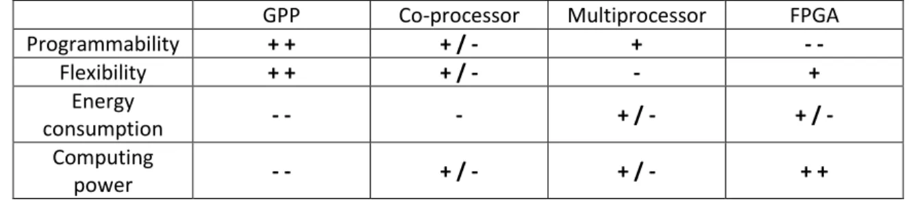
Because most platforms are heterogeneous, the classification and evaluation of them can be a tricky task. In this document, the platforms are introduced following four features: programmability, flexibility, energy consumption and computing power. The programmability stands for the capacity to modify the “software” in the radio system. The flexibility stands for the capacity to support various architecture designs.
There are many kinds of SDR platform [34] which have been proposed to implement SDR. Each of them has different advantages and disadvantages based on the approach it relies on. In this section, SDR platforms are divided into four main approaches:
• General Purpose Processor approach • Co-processor approach
• Multi-processor approach • FPGA approach
This section aims at providing an overview of different platforms used to implement SDR. 2.5.1. General Purpose Processor (GPP) Approach
A general Purpose Processor (GPP) is a typical microprocessor which is widely used in personal computer or smart phone. GPP provides a high flexibility and an easy development environment. A wide range of operating systems and qualified developers make GPP the easiest platform to develop SDR. However, GPP is only suitable for applications for which power consumption and computation capability
36
is not critical. In addition, the operating system running in GPP normally creates latency. Thus, GPP approach has high latency and is not suitable for hard real-time applications.
The USRP platform (Universal Software Radio Peripheral) [35] is a famous example of GPP approach in SDR. In this platform, the signal processing is performed mostly on GPP and a FPGA is used to store output data from the ADC. It is developed to work mainly with GNU Radio [35]but is also supported by Labview or Matlab.
SORA [36] is another example of GPP approach of Microsoft. In this platform, a PCIe (Peripheral Component Interconnect Express) bus is used to accelerate the connection between the platform and the computer. Thus, the latency is reduced and the data rate is increased. By this way, it is possible to decode the Wi-Fi 802.11 b/g in real time.
The ongoing development of microelectronics technology pushes to believe that future computers will be able to decode real-time protocols. However, because the data flow to be processed is increasing faster than the computing power [37], it is difficult to support advanced protocols using such platforms.
2.5.2. Co-processor Approach
Co-processor platforms are composed of a GPP and additional hardware resources to enhance computation capability. The additional resources are usually Advanced RISC Machines (ARMs), Digital Signal Processors (DSPs), FPGAs or a combination of them. They are used to perform heavy calculations of the applications. Unlike GPP platforms that have high latency, the high processing power of co-processors allows to run real-time applications. Such an approach can also be used to reduce the power consumption while trying to maintain a high flexibility and a simple programmability required by SDR platform. However, a combined architecture makes the programming model of this approach dependent of the hardware and reduces the flexibility.
The Kuar platform (Kansas University Agile Radio) [38] uses a GPP combined with a FPGA. To use this platform, the developer can design the application using GNURadio. When available in a predefined library of VHDL (VHSIC Hardware Description Language) IPs, a processing block can be run either on the GPP or on the FPGA.
Horrein, Hennebert and Pétrot [39] proposed a SDR platform that uses a Graphics Processing Unit (GPU) as a coprocessor for heavy computations. They use the GNURadio as a computing environment. The platform is divided between a host (GPP) and computing devices (GPU). The final system can gain three to four times the GPP computing power.
IMEC developed the ADRES platform (Architecture for Dynamically Reconfigurable Embedded Systems) [40]. It includes a central CPU and the ADRES accelerator. ADRES is a grid of 16 functional units, seen by the processor as a VLIW (Very Large Instruction Word) co-processor. This architecture helps the platform to process data in parallel and its compiler DRESC enables the design of reconfigurable 2D array processors making a powerful reconfigurable architecture. The ADRES platform targets both the 108 Mbps 802.11n and 18 Mbps LTE standards with an average consumption of 333 mW.
37
However the above architectures still have limited capability on parallel processing. This may reduce their computing power. The next approaches offer a better task parallelism.
2.5.3. Multiprocessor Approach
In this approach, a main processor is used for control. The other processors are dedicated processors for signal processing which can run in parallel. In some platforms, in order to reduce energy consumption, dedicated processors are only configurable units. Although the flexibility of this approach is reduced, it provides high programmability. This approach is presented in the Figure 2.12. In this figure, a group of processors which are connected to each other responds to the needs for signal processing tasks before sending the data to the Frond-End.
Tomahawk [41] developed by the University of Dresden is a platform for LTE and WiMAX. Two processors Tensilica RISC are used for control while six vector DSPs and two scalar DSPs are used for signal processing. The C language is used to program this platform. According to the authors' estimation, the power consumption of the platform is about 1.5 W.
The University of California at Davis develops smart ASAP (Asynchronous Array of Simple Processors) [42]. The objective of the project is to achieve signal processing computations on small processors within limited power budgets. All processors can communicate with their nearest neighbors on a grid. This platform offers a good compromise between programmability and performance. A 54 Mbps 802.11a/g standard was fully implemented in this platform with a consumption power of about 198 mW.
Magali [43] is a software radio platform developed by CEA LETI. This platform uses configurable units for dedicated processors. It is based on a Network on Chip (NoC) controlled by an ARM processor. The computation is performed by specialized DSPs and reconfigurable IPs for OFDM modulation. The chip runs the LTE protocol in 4x2 MIMO transmission mode with a power consumption of about 236 mW [44].
Figure 2.12 Multi-processor approach.
The ExpressMIMO platform [45] is built by EURECOM. It has configurable units which share a common network interface. The platform implements MIMO OFDM encoding method used in several protocols such as Wi-Fi and LTE. The open-source OpenAirInterface framework [46] is used for this platform.
38 2.5.4. FPGA Approach
The last type of platform relies on FGPA hardware which uses many configurable logic blocks to build the system. Unlike other approaches, the FGPA approach may not use processor(s). FPGAs make use of many low grain logic components, called Logic Blocks (LBs), and many interconnections as shown in Figure 2.13. LBs can be configured by the user for various purposes such as implementing combinational logic. Current FPGAs are also composed of macro blocks to support specific functions such as RAMs, DSP slices and interfaces to external devices. Because of their architecture allowing parallel processing, FPGAs have a high computation capability for moderate energy consumption. In addition, the capacity to implement and to run only the necessary parts makes FPGAs quite efficient in power saving mode.
Figure 2.13 FPGA-based approach.
WARP [47] is an open SDR platform developed by Rice University. It provides a MIMO OFDM reference design and is used in many research projects. This platform is based on a Xilinx Virtex II Pro FPGA and is designed to be programmed using VHDL language.
The Nutaq company [48] provides various development tools and a software radio platform based on FPGAs. The development is carried out on Simulink or VHDL. These platforms can support MIMO WiMAX.
Rutgers University has developed WINC2R [49], a SDR platform built on a Xilinx Virtex 4 FPGAchip. It uses both softcore processors i.e. processor cores that are wholly implemented using LBs and dedicated hardware accelerators. Depending on the constraints, the processing can be balanced between softcore processors and accelerators. Unlike the previous approaches, with this platform the system can choose to use accelerators or not. An 802.11a waveform has been implemented on the platform.
The FPGA approach provides a flexible platform for prototyping using FPGA technology. It offers high computing power for moderate energy consumption. We will discuss in more details this approach on the next section.
39
GPP Co-processor Multiprocessor FPGA
Programmability + + + / - + - - Flexibility + + + / - - + Energy consumption - - - + / - + / - Computing power - - + / - + / - + +
Table 2.2 A comparative study between different approaches for SDR.
To sum up, Table 2.2 compares the four approaches based on the four criteria previously mentioned: programmability, flexibility, energy consumption and computing power. However, as previously noticed, most platforms are heterogeneous and a specific platform may need a detailed evaluation.
2.6. FPGA-based SDRs
Using FPGAs to implement SDR has many advantages. Due to its high computing power combined with parallel processing capability, FPGAs can support high data rates and consequently a wide variety of waveforms. Although it does not provide high programmability compared to other approaches, a FPGA is very flexible and suitable to support various architectures. Thus, FPGA-based SDR is expected to play an important role in SDR.
There are 3 ways to implement various waveforms on a FPGA: • Multi-waveform configuration
• Separated configuration • Partial reconfiguration
2.6.1. Multi-waveform Configuration
In this configuration, the bitstream (i.e. the file to configure the LBs and interconnection switches) keeps all the expected waveforms. According to the used waveform, all the features are set and configured by appropriate registers at runtime. This approach has the ability of instantaneously switching among configurations. However, because the bitstream is designed to support all the waveforms, it usually costs a lot of memory and resources. This solution becomes therefore impossible when a large number of waveforms are targeted. In most cases, the designer optimizes the code by grouping the common parts among waveforms and also tries to share common resources among waveforms but it costs time and can make the code significantly complex. One other disadvantage of this approach is the difficulty to upgrade or implement a new waveform that needs to make a fully new bitstream. Moreover, this approach normally achieves lower throughput because the bitstream has to support multiple waveform. This approach is quite suitable with similar waveforms. Indeed, there are several related waveforms and the firmware needs only few changes to support other kind of waveforms. Massouri [50] developed a SDR a using this configuration on the Nutaq family of board Perseus 6011 (Virtex 6 FPGA). The options with different frequency bands of IEEE 802.15.4 have been accomplished on this platform. Zlydareva
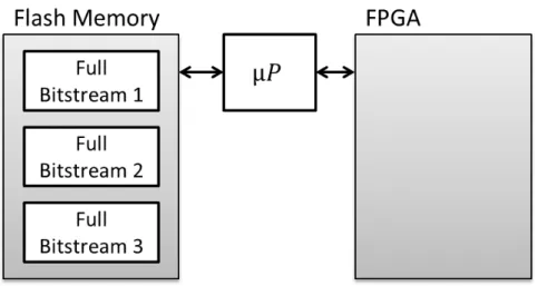
40 2.6.2. Separated Configurations
In this approach, each waveform is designed in a separated bitstream and is stored in an external memory as illustrated in Figure 2.14. According to the used waveform, the associated bitstream is loaded to the FPGA whenever it is required. This configuration does not need a large number of resources and easily suits various architectures. Moreover, it is very easy and fast if the designer needs to change or upgrade a specific waveform because every configuration is designed independently. In addition, only the required resources are configured and run for one waveform at a time. This saves energy and resources. However, unlike a GPP, it takes time for a FPGA to load a new configuration. It is a drawback of this approach. In practice, this approach is not often applied. Actually, current FPGAs can implement enough resources so that the multi-waveform configuration is preferred even if it is usually more complex to design.
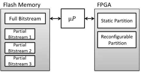
Figure 2.14 Separated configurations. 2.6.3. Partial Reconfiguration
An interesting feature of some FPGAs is partial reconfiguration (PR). Such FPGAs can load a new bitstream to only a small part of the hardware device while the other parts normally run. Although PR technique has been introduced for a long time, the associated design tools were quite limited and not very well supported by major FPGA manufacturers. Thus, PR was not easy to use and only few SDR platforms include this feature [52] [53].
When using PR, FPGA resources are split in several partitions:
- one or more reconfigurable partitions, where different configurations or different blocks of a new targeted waveform can be loaded at run time,
- one or more static partitions, where the processing are initially loaded, continuously run while reconfigurable partitions are modified in a PR process.
This method is presented in the Figure 2.15. In this method, a full bitstream, i.e. a bitstream which contains the configuration for a waveform, is first loaded. Whenever the firmware needs to change the waveform, it will load the partial bitstream which contains only the different configuration parts of a new waveform.
![Figure 2.9 Physical layer coding rate as a function of channel conditions and modulation scheme [31]](https://thumb-eu.123doks.com/thumbv2/123doknet/11500946.293638/33.918.152.773.131.372/figure-physical-coding-function-channel-conditions-modulation-scheme.webp)
![Figure 2.11 An eight-point DFT, divided in four two-point DFTs with bit reversal on inputs [33]](https://thumb-eu.123doks.com/thumbv2/123doknet/11500946.293638/35.918.97.770.306.964/figure-point-dft-divided-point-dfts-reversal-inputs.webp)