HAL Id: hal-00785836
https://hal.archives-ouvertes.fr/hal-00785836
Submitted on 7 Feb 2013
HAL is a multi-disciplinary open access
archive for the deposit and dissemination of
sci-entific research documents, whether they are
pub-lished or not. The documents may come from
teaching and research institutions in France or
abroad, or from public or private research centers.
L’archive ouverte pluridisciplinaire HAL, est
destinée au dépôt et à la diffusion de documents
scientifiques de niveau recherche, publiés ou non,
émanant des établissements d’enseignement et de
recherche français ou étrangers, des laboratoires
publics ou privés.
MULTI-TEXTURING 3D MODELS: HOW TO
CHOOSE THE BEST TEXTURE?
Youssef Alj, Guillaume Boisson, Philippe Bordes, Muriel Pressigout, Luce
Morin
To cite this version:
Youssef Alj, Guillaume Boisson, Philippe Bordes, Muriel Pressigout, Luce Morin.
MULTI-TEXTURING 3D MODELS: HOW TO CHOOSE THE BEST TEXTURE?. IC3D, Dec 2012,
Bel-gium. �hal-00785836�
MULTI-TEXTURING 3D MODELS:
HOW TO CHOOSE THE BEST TEXTURE?
Youssef Alj, Guillaume Boisson, Philippe Bordes
Technicolor
1 avenue Belle Fontaine CS 17616
35576 Cesson-Sévigné Cedex
France
Muriel Pressigout, Luce Morin
INSA Rennes
20 avenue des Buttes de Coësmes
35043 Rennes Cedex
France
ABSTRACT
In this article, the impact of 2D based approaches for multi-texturing 3D models using real images is studied. While conven-tional 3D based approaches assign the best texture for each mesh triangle according to geometric criteria such as triangle orientation or triangle area, 2D based approaches tend to mi-nimize the distortion between the rendered views and the ori-ginal ones. Evaluation of the two strategies is performed on real scenes for two image sequences and results are provi-ded using the PSNR metric. Moreover, an improvement of the image-based approach is proposed for texturing partially visible triangles.
Index Terms— Multi-texturing, best texture, OpenGL, mesh, PSNR.
1. INTRODUCTION
Since the introduction of texture mapping in computer graphics in the mid seventies, acquiring photo realistic 3D models has become necessary for various applications such as cultural heritage, architecture and entertainment industry. Ty-pically in such applications, one seeks to texture a 3D model given a set of photographs captured from various viewpoints. The straightforward approach for texturing the 3D model is to determine the best texture for each mesh facet. The point is then to find a criterion to define the best texture. 3D geo-metric criteria such as angle between the line of sight and the triangle orientation [3], distance to the viewing camera [2] or facet’s area [8] may be considered to solve this problem. The aim of multi-texturing is to determine the texture provi-ding the best rendering. To this end, photoconsistency based multi-texturing was introduced in [1]. It aims to assign for each mesh triangle the best texture by minimizing the 2D dis-tortion, i.e. the quadratic error between the rendered and ori-ginal views. Given these approaches, we attempt to address the following questions : what is the impact of an approach based on 2D distortion on the quality of the rendered views ? And do 2D approaches really add a significant improvement
in terms of PSNR ? In this paper we present a comparison between texture selection using 3D geometric criteria and a 2D approach based on distortion minimization of the rende-red images. This distortion is measurende-red using the PSNR me-tric classically used within the video coding community. Ac-tually, the PSNR metric is employed in order to evaluate fide-lity between a reference and recovered image. In this study, this metric is used for both assigning the best texture to mesh triangles as well as for comparing geometric versus image ba-sed criteria for multi-texturing 3D models. The contributions of this paper are twofold :
– First, we study the impact, on the rendered views, of using geometric versus image based criteria for multi-texturing 3D models.
– Second, we extend the photoconsistency based multi-texturing method to handle partially visible triangles.
2. RELATED WORK
View Dependent Texture Mapping was first introduced by Debevec et al. in [3] with real time application in [4]. In this scheme, the user specifies a virtual view to render the mesh, and the best texture for each mesh triangle is chosen as the one the minimizes the angle between the triangle normal and the viewing directions of input cameras. For instance, when generating a novel view from the left, it would be better to use the image corresponding to the left view as the texture map. View Dependent Texture Mapping approaches consider the transmission of the set of all textures which requires a tre-mendous amount of data. The Floating Textures scheme [5] alleviates inaccuracies inherent to the geometric model and the camera calibration, and proposes a pairwise warping bet-ween input images using optical flow. Instead of using the optical flow, Harmonised Texture Mapping [9] used an opti-mized version of the input mesh in order to control the range of texture deformation. Lempitsky and Ivanov [8] formulate multi texturing the 3D model as a labelling problem : each texture should be assigned as a label to the mesh triangle. They expressed their labelling strategy as on energy
minimi-zation problem with two terms, the first one describing how better an input texture suits the triangle and the second one penalizing seams’ visibility. Computation of the best texture per triangle is based on the angle between the viewing direc-tion and the triangle normal. Based on energy minimizadirec-tion scheme, Gal et al. [6] extend the best texture search space to include a set of transformed images that compensate geome-tric errors and make use of Poisson blending to address ligh-ting variation. The Unstructured Lumigraph Rendering me-thod [2] uses a penalty function for each view in order to determine the best view for each triangle, this penalty is a linear combination of three terms : visibility constraints, the angle between the desired view to render and the set of input cameras and the resolution of the projected triangle. Other ap-proaches form a single texture map by blending the available images. In [10], the unique texture map generation is presen-ted as a super resolution problem [7]. The authors used image processing tools to compute the correct weights for blending. Finally, a 2D criterion for best texture selection is based on photoconsistency with the set of input images was first pro-posed in [1]. Their idea is based on distortion minimization between the rendered and original views. This distortion is measured in terms of quadratic error.
In this paper, we compare the impact of multi-texturing 3D models using geometric criteria, namely triangle orientation and triangle area, versus using 2D criterion based on photo-consistency on the other hand.
3. GEOMETRIC CRITERIA FOR MESH TEXTURING
Given a triangular mesh M and a set of texture images I = {I1, . . . , In}. Each texture Ii is respectively captured
from the views V = {V1, . . . , Vn}. The aim is to find for
each mesh triangle t ∈ M the best texture image ˆIt ∈ I
using a geometric criterion Ck, where Ckcould be one of the
following criteria :
– C1:= h ~dj, ~nti i.e. dot product between triangle normal
~
ntand viewing direction (i.e. optical axis, that is image
plane normal) ~djof the view Vj. Small angles between
triangle normal and viewing directions of input came-ras are then preferred. Note that in the case of parallel camera setup this criterion is not applicable.
– C2 := h~ej, ~nti, where ~ej denotes the direction of the
ray joining the triangle barycenter and the camera’s po-sition. Views where the triangle’s viewing cone is larger are then preferred.
– C3 := areaj(t) the area of the projected triangle onto
the view Vj. Views where the resolution of the
projec-ted triangle is larger are then preferred.
Let Pj(t) denote the projection of triangle t onto the view
Vj. Pj(t) consists in a set of pixels (q, l) corresponding to the
rasterization of triangle t, e.g. using OpenGL rendering en-gine. The best texture ˆItis computed the following way : first
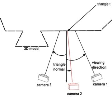
Fig. 1. Best texture selection as the minimizer of the angle between the triangle normal and cameras viewding direcions.
for each triangle t, total and partial visibility are determined with respect to each view. The best texture is then determined as the maximizer of Ckwith respect to visibility constraints.
Figure 1 illustrates the principle of best texture selection using C1. This figure shows that the best view to texture the triangle
t is the camera 2. Indeed, the angle between the viewing di-rection of the camera 2 and the triangle normal is minimum, which corresponds to a maximum dot product.
3.1. Visibility determination
Given the input mesh M, total and partial visibility are first determined for each triangle with respect to each view. At the end of this step, each triangle will have one of the three labels per view : "totally visible", "partially visible" or "hid-den". The algorithm is detailed in the next section.
3.1.1. Total visibility
In this step only the labels "totally visible" and "hidden" are assigned to mesh triangles. The status of each mesh tri-angle is initialized to "totally visible". The visibility of each triangle is determined by computing the visibility of the tri-angle vertices. A tritri-angle is marked as hidden if at least one of its vertices is hidden. Vertex visibility with respect to each ca-mera is determined using OpenGL z-buffer denoted as Zbufferj (i.e. z-buffer of the mesh projected onto the view Vj).
Du-ring the first pass, the input mesh is projected onto the current view, and the z-buffer is extracted. The second pass is dedi-cated to vertex visibility determination using the computed z-buffer. Each mesh vertex is projected onto the current view and the depth component, denoted as zprojected, is checked
against the pixel depth Zbufferj [q, l]. If the projected vertex is behind the pixel in the z-buffer, then this vertex is hidden, and thus the set of mesh triangles sharing this vertex are marked hidden. The pseudo-code for total visibility determination is provided in algorithm 1.
Algorithm 1: Global visibility determination. // Views traversal
for each view Vjdo
Initialize all triangles to visible. Project the M onto Vj.
Store the depth buffer Zbufferj .
// Mesh vertices traversal for each vertex v do
Determine (q, l, zprojected) the projection of the
vertex v onto Vj.
if Zbufferj [q, l] > zprojectedthen
v is a hidden vertex.
Mark all the triangles lying on v as hidden.
3.1.2. Partial visibility
Until now, each triangle has one of the two labels : "totally visible" or "hidden". At the end of this step, "hidden" triangles will be sorted out as "partially visible" or totally "hidden". To this end the depth of each pixel is checked against the stored depth buffer in the projected triangle. Note that it is necessary to check the depth of the projected triangle. Partial visibility determination by counting the number of hidden vertices is not sufficient as some triangles could be partially visible and have a number of hidden vertices of three. The algorithm de-termining partial visibility is presented in algorithm 2.
Algorithm 2: Partial visibility determination. // Views traversal
for each view Vjdo
// Mesh triangles traversal for each triangle t do
if triangle t is hidden in Vjthen
Determine Pj(t) the projection of triangle t
onto Vj.
for each pixel (q, l) in Pj(t) do
Get the pixel depth z. if z == Zbufferj [q, l] then
Mark t as partially visible in Vj.
3.2. Best texture computation using geometric criterion In this section the best texture is assigned to the set of tri-angles which are totally or partially visible using one of the three criteria discussed above. Algorithm 3 describes how the best texture is assigned for such triangles. The user specifies a geometric criterion Ck. The view that maximizes Ck is
as-signed as the best texture for the current triangle.
Algorithm 3: Best texture determination using Ck.
// Triangles traversal for each triangle t do
Get the normal of the triangle t. // Views traversal for each view Vjdo
if t is visible or partially visible in Vjthen
Compute Ck.
Compute ˆItwhich maximizes Ck
4. PHOTO-CONSISTENCY BASED MESH TEXTURING
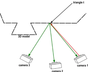
Photoconsistency based mesh texturing was first introdu-ced in [1]. Figure 2 illustrates the photoconsistency principle. The triangle t is visible in cameras 1, 2, 3. For each texture Ii ∈ I, the triangle t is textured with texture Ii (red arrow
for texture mapping operation) and projected (green arrow for projection operation) onto the cameras 1, 2, and 3 - i.e. the set of cameras where t is visible. The error of texturing the triangle t with each available texture is computed. This error is referred to as the photoconsistency metric. The best texture is chosen as the minimizer of the photoconsistency metric. In [1] only totally visible triangles are addressed, and partially visible ones are textured using the view of the frontal camera. The novelty of the approach described in this paper is to extend the photoconsistency-based best texture computa-tion for partially visible triangles too. The overall framework is sketched in Figure 3. First, visibility is determined for each triangle with respect to each view. Second, each available tex-ture is mapped on visible triangles of the input mesh. Photo-metric projection error is computed for each triangle and for each input view and stored in distortion images. Synthesized views are produced by rendering the textured mesh, each tri-angle being textured with the best texture according to the photoconsistency metric. In the next section each step of this algorithm is described in more details.
Fig. 2. Best texture determination using photoconsistency. Red arrow for texture mapping operation and green arrow for projection operation.
Fig. 3. Overall framework.
4.1. Distortion images determination
In order to determine the error of texturing a triangle with an input texture Ii, each available texture is then mapped on
the merged mesh and projected onto each camera. Let Pi j(M)
be the projection of the mesh M onto the view Vj textured
with the image Ii. For each available texture the following
distortion image is computed in RGB color space : Di,j= kPji(M) − Ijk2
4.2. Best texture determination
In this section, the best texture is chosen for each mesh triangle using the distortion images. The best texture for each triangle relies on the computed set of pixels that belong to the projected triangle and visible in the current view Vj, i.e. the
Algorithm 4: Compute distortion images. // Textures traversal
for each texture Iido
// Views traversal for each view Vjdo
Compute Pi
j(M) : projection of the mesh
textured with texture Iionto view Vj.
Di,j= kPji(M) − Ijk2
set of pixels :
Visj(t) = {(q, l) ∈ Pj(t), (q, l) visible in Vj}
Figure 4 shows how Visj(t) is determined for partially and
totally visible triangles. The grid represents image pixels. In 4(a) the blue triangle is totally visible, the set of pixels de-fining Visj(t) are shown in red. On the contrary, the blue
triangle in 4(b) is partially visible as it is occluded by the green triangle. Visj(t) in this case is restricted to the
non-occluded pixels. The photoconsistency metric is then com-puted for each triangle with respect to Visj(t). This metric
measures the error of texturing the triangle t with the texture image Ii. From here on, for sake of simplicity, visible triangle
will refer to totally or partially visible triangle as they will be treated the same way.
∀i ∈ {1, . . . , n} we compute : Et,Ii= n X j=1 t visible in Vj X (q,l)∈Visj(t) Di,j[q, l] ,
The best texture for a visible triangle t is then given by : ˆ
It= arg min Ii∈I
Et,Ii .
The steps of best texture computation are summarized in al-gorithm 5.
Algorithm 5: Compute the best texture for each tri-angle.
// Triangles traversal for each triangle t do
// Views traversal for each view Vjdo
Determine Visj(t).
// Textures traversal for each texture Iido
Compute Et,Ii.
4.3. Texture mapping
Finally, the views are rendered. The 3D model is projected according to the camera’s parameters supplied by the user. Then each triangle is textured using the texture coordinates determined during visibility determination step.
(a) total visibility (b) partial visibility
Fig. 4. Best texture computation. Handling partial/global vi-sibility.
5. IMPLEMENTATION AND RESULTS Results are presented for two sequences breakdancers and balloons. Breakdancers, provided by Microsoft, is captured by eight convergent cameras. Balloons sequence, provided by Nagoya University, is captured by three parallel cameras. Both sequences have XGA resolution (1024x768). The geo-metric model used in this study is based on the 3D reconstruc-tion scheme presented in [1].
Results of the rendered views are provided in figure 6 and in figure 5. It can be seen that photoconsistency based mesh texturing provides better visual quality than geometric based methods. More precisely, in figure 5, the frontier between the two brown walls is well-aligned using the photoconsistency criterion, while this frontier is misaligned using the geometric criterion. Besides, the floor appears to be noisy using geome-tric criterion, while it is much smoother using the photocon-sistency criterion. Figure 7 shows that the difference in terms of PSNR between photoconsistency criterion and any other geometric criterion is noticeable ( the average difference is at least 1dB between the two methods).
Regarding the photoconsistency criterion, results also show that PSNR is higher for cameras near the frontal camera (see Figure 7), which is due to the large number of triangles assi-gned to the texture of the frontal camera. However, photocon-sistency based multi-texturing algorithm is time-consuming (about 10x more) comparing to geometric methods. There-fore it turns out that photoconsistency based multi-texturing is best suited for offline rendering. These results suggest the use of the photoconsistency based multi-texturing for trans-mission purposes where distortion minimization is often a key element to take into account.
Fig. 7. PSNR evolution through different views using dif-ferent criteria for Breakdancers and Balloons sequences.
6. CONCLUSION
In this paper, multi-texturing 3D models was addressed by considering several criteria for best texture assignment to mesh triangle. Conventional geometric criteria assign the view that minimizes the angle between the viewing direction and the triangle normal, or the view that maximizes the triangle resolution. On the contrary, 2D based approaches minimize the distortion between the rendered views and the original ones. We show that photoconsistency based methods are si-gnificantly more relevant for transmission purposes. Indeed they outperform geometric based methods both in terms of objective and subjective visual quality of synthesized views. The PNSR gap exceeds 2dB for the common test-sequences. As a perspective, we plan to investigate how to reduce com-plexity without altering too much the quality of the synthe-sized views. We also aim to improve spatial consistency of the assigned textures in order to reduce the coding cost of the
texture signal.
7. REFERENCES
[1] Y. Alj, G. Boisson, P. Bordes, M. Pressigout, and L. Mo-rin. Space carving mvd sequences for modeling natural 3d scenes. volume 8290, page 829005. SPIE, January 2012.
[2] C. Buehler, M. Bosse, L. McMillan, S. Gortler, and M. Cohen. Unstructured lumigraph rendering. In Pro-ceedings of the 28th annual conference on Computer graphics and interactive techniques, pages 425–432. ACM, 2001.
[3] P.E. Debevec, C.J. Taylor, and J. Malik. Modeling and rendering architecture from photographs : A hybrid geometry-and image-based approach. In Proceedings of the 23rd annual conference on Computer graphics and interactive techniques, pages 11–20. ACM, 1996. [4] P.E. Debevec, Y. Yu, and G. Borshukov. Efficient
view-dependent image-based rendering with projective texture-mapping. In Eurographics Rendering Workshop, volume 98, pages 105–116, 1998.
[5] Martin et al. Eisemann. Floating textures. Computer Graphics Forum (Proc. of Eurographics), 27(2) :409– 418, April 2008.
[6] R. Gal, Y. Wexler, E. Ofek, H. Hoppe, and D. Cohen-Or. Seamless montage for texturing models. In Compu-ter Graphics Forum, volume 29, pages 479–486. Wiley Online Library, 2010.
[7] M. Iiyama, K. Kakusho, and M. Minoh. Super-resolution texture mapping from multiple view images. In Pattern Recognition (ICPR), 2010 20th International Conference on, pages 1820–1823. Ieee, 2010.
[8] V. Lempitsky and D. Ivanov. Seamless mosaicing of image-based texture maps. In Computer Vision and Pat-tern Recognition, 2007. CVPR’07. IEEE Conference on, pages 1–6. IEEE, 2007.
[9] T. Takai, A. Hilton, and T. Matsuyama. Harmonised tex-ture mapping. In Proc. of 3DPVT, 2010.
[10] L. Wang, S.B. Kang, R. Szeliski, and H.Y. Shum. Opti-mal texture map reconstruction from multiple views. In Computer Vision and Pattern Recognition, 2001. CVPR 2001. Proceedings of the 2001 IEEE Computer Society Conference on, volume 1, pages I–347. IEEE, 2001.
(a) Original image camera 7 (b) Zoom on original image camera 7
(c) Synthesized image camera 7 using viewing cone criterion C2 (d) Zoom on synthesized image camera 7 using viewing cone criterion C2
(e) Synthesized image camera 7 using photoconsistency (f) Zoom on synthesized image camera 7 using using photoconsistency
(a) Original image camera 5 (b) Zoom on original image camera 5
(c) Synthesized image camera 5 using triangle resolution criterion C3 (d) Zoom on synthesized image camera 5 using triangle resolution cri-terion C3
(e) Synthesized image camera 5 using photoconsistency (f) Zoom on synthesized image camera 5 using photoconsistency