Science Arts & Métiers (SAM)
is an open access repository that collects the work of Arts et Métiers Institute of
Technology researchers and makes it freely available over the web where possible.
This is an author-deposited version published in: https://sam.ensam.eu Handle ID: .http://hdl.handle.net/10985/19555
To cite this version :
Duc Tan VU, Ngac Ky NGUYEN, Eric SEMAIL - Eliminations of Low-frequency Current Harmonics for Five-phase Open-end Winding Non-sinusoidal Machine Drives applying Neural Networks - In: The 46th Annual Conference of the IEEE Industrial Electronics Society (IES), Singapour, 2020-10-18 - The 46th Annual Conference of the IEEE Industrial Electronics Society (IES)-IECON 2020 - 2020
Any correspondence concerning this service should be sent to the repository Administrator : archiveouverte@ensam.eu
Eliminations of Low-frequency Current Harmonics
for Five-phase Open-end Winding Non-sinusoidal
Machine Drives applying Neural Networks
Duc Tan Vu ductan.vu@ensam.eu Ngac Ky Nguyen ngacky.nguyen@ensam.eu Eric Semail eric.semail@ensam.eu Univ. Lille, Arts et Metiers Institute of Technology, Centrale Lille, Yncrea Hauts-de-France,ULR 2697-L2EP, F-59000 Lille, France Abstract—This study aims at eliminating unwanted
harmonics in current control of a five-phase non-sinusoidal permanent magnet synchronous machine (PMSM) in an open-end winding configuration. The machine is supplied by two voltage source inverters (VSIs) using a single DC-bus voltage. High-frequency harmonics, caused by the zero-sequence current with the inverter switching frequency, have been significantly reduced by using a proper pulse width modulation (PWM) strategy. Meanwhile, low-frequency current harmonics are generated by unwanted harmonics of the back electromotive force (back-EMF) and by the inverter nonlinearity. In this study, the low-frequency current harmonics are nullified by simple adaptive linear neural networks (ADALINEs) in rotor reference frames combined with the back-EMF compensation. As a result, the quality of current control is improved. The effectiveness of the proposed strategies is verified by numerical results.
Keywords—Multiphase PMSM, five-phase machine, open-end winding, low-frequency current harmonic, back-EMF compensation, ADALINE, artificial intelligence.
I. INTRODUCTION
Electric drives using multiphase machines have drawn attentions from industry due to their advantages over the conventional three-phase machines. The summary of design, modeling and control of the multiphase has been reported in [1]. For low-voltage applications (<60 V, safe for humans), open-end windings have several advantages such as doubled phase voltages for a given DC-bus supply and more degrees of freedom for control, compared to wye-connected windings. However, the high-frequency zero-sequence current can circulate in the open-end winding topology. This current generates high-frequency components in phase currents, increasing copper losses and oversizing of switches. These problems have been investigated in [2]. It is concluded that using the three-level double PWM modulation reduces most of the switching-frequency components in the currents.
Besides the high-frequency problem related to the open-end winding topology, low-frequency current harmonics can reduce the current control quality. These harmonics are mainly originated from machine design and inverter nonlinearity [3, 4]. According to the multi-reference frame theory [5], the control is ideal if only one harmonic is associated with each rotating reference frame. In addition, the zero-sequence frames should not contain any harmonics for the open-end winding configuration. As a result, all currents and back-EMFs are constant in rotating reference frames, creating constant torques. Thus, in general, a n-phase machine should contain only (n-1)/2 harmonics in its back-EMF [5]. In a 3-phase machine, in rotor reference frames, there is only one rotating (d-q) and one zero-sequence reference frame. Thus, it is ideal that its back-EMF is purely
sinusoidal to create a constant torque with constant d-q currents. However, the machine design and saturation may create unwanted harmonics in the back-EMF. In a multiphase machine, the presence of more harmonics in its back-EMF is accepted. For example, in a 5-phase machine, there are two d-q and one zero-sequence frames. It means that two is the maximum number of harmonics that should exist in the back-EMF to create constant torques with constant d-q currents. Nevertheless, like the discussed issue of the 3-phase machine, more than one back-EMF harmonic is associated with each d-q frame or harmonics exist in the zero-sequence frame. These unwanted back-EMF harmonics not only cause current harmonics in d-q and zero-sequence frames but also pulsating torques. In addition, the inverter nonlinearity causes dead-time voltages, resulting in extra current harmonics in d-q frames. The inverter nonlinearity with dead-time voltages is modeled and estimated in [6, 7] for inverters with different numbers of legs. To eliminate current harmonics, study [8] uses low-pass filters (LPFs) to obtain harmonics from winding currents. By using these obtained harmonics, the disturbance injection can be implemented. The LPFs are combined with a close-loop detection to avoid the delay. However, the computation is complicated. Hence, study [9] applies ADALINEs to compensate the dead-time voltages for a 3-phase PMSM. Meanwhile, study [10] applies ADALINEs to suppress current harmonics for a 3-phase non-sinusoidal wye-connected winding machine. Specifically, both the unwanted back-EMF harmonics and the dead-time voltages are considered. The studies [9, 10] motivate the use of ADALINEs in a multiphase drive. For multiphase machines, there have been some studies to eliminate current harmonics. Study [11] applies an improved model predictive control to reduce the voltage and current harmonics for a wye-connected 5-phase PMSM. However, high frequency components still exist in currents and torques. An inverse model-based disturbance observer in [12] is applied to eliminate current harmonics for a dual 3-phase machine. Its calculating complication can be considered as an inconvenience.
In this study, a hybrid self-learning strategy to eliminate low-frequency current harmonics is presented for 5-phase open-end winding non-sinusoidal PMSM drives. The compensating signals are generated by simple ADALINEs combined with back-EMF harmonics in rotor reference frames. The current control quality is improved regardless of the distortions caused by the presence of the unwanted back-EMF harmonics and the inverter nonlinearity. Especially, the dynamic performances are guaranteed when either the rotating speed or current references change.
This paper is organized as follows. The modeling of the considered drive is presented in section II. The current harm-
Fig. 1. Topology of an electric drive using a 5-phase open-end winding PMSM fed by two voltage source inverters and a single DC-bus voltage. -onic elimination strategy is proposed in section III. Then, section IV shows numerical results to verify the effectiveness of the proposed method.
II. MODELING OF AN OPEN-END WINDING 5-PHASE PMSM
DRIVE
In this study, a 5-phase PMSM with non-sinusoidal back-EMF is considered. Several assumptions of the machine are described as follows: apart from the 1st harmonic, the 3rd
harmonic accounts for the second highest proportion, the unwanted harmonics such as 5th, 7th, 9th and 15th have small
but unneglected proportions in the back-EMF; the machine has 5 phases equally shifted; the magnet circuit saturation is not considered in the back-EMF and flux calculations.
The topology of the considered drive is presented in Fig. 1. Two inverters VSI1 and VSI2 are fed by a single DC-bus voltage. Each phase of the 5-phase machine is connected to one leg of VSI1 and one leg of VSI2. Thus, the voltage applied to the machine can be written as follows:
-= VSI1 VSI2 v v v (1) with
T A B C D E T A1N B1N C1N D1N E1N T A2N B2N C2N D2N E2N v v v v v v v v v v v v v v v = = = VSI1 VSI2 v v vwhere v, vVSI1 and vVSI2 are the 5-dimensional vectors of the machine phase voltages, leg voltages of inverters VSI1 and VSI2 compared to the neutral point N, respectively.
In addition, the machine voltages can be expressed as in (2).
s d R + dt = i+ v i L e (2)where i and e are the 5-dimensional vectors of phase currents and back-EMFs, respectively; 𝑅𝑠 is the resistance of stator; [𝑳] is a 5 by 5 stator inductance matrix.
To control the machine drive using the field-oriented control (FOC), Clarke and Park transformation matrices are applied to convert the machine parameters from natural frame into rotor reference frames. The transformation for currents is presented in (3). In the new reference frames, the 5-phase machine is decomposed into two fictitious 2-phase machines (FM1 and FM2) with rotating frames (d1-q1) and (d3-q3) respectively, and one zero-sequence machine (ZM) with reference frame z [5]. A fictitious machine (reference frame) is associated with a given group of harmonics as presented in Table I. In rotor reference frames, values of machine parameters (currents and back-EMFs) are expected to be constant for control as well as to obtain a constant torque.
T
Td1 q1 d3 q3 z A B C D E
i i i i i = P C i i i i i (3)
TABLE I
FICTITIOUS MACHINES AND ASSOCIATED HARMONICS OF AFIVE-PHASE
MACHINE (ONLY ODD HARMONICS)
Fictitious machine Frame Associated harmonic (m 0) 1st machine (FM1) d 1-q1 1, 9, 11, …5m ± 1 2nd machine (FM2) d 3-q3 3, 7, 13, …5m ± 2 Zero-sequence machine (ZM) z 5, 15, …5m with ( ) ( ) ( ) ( ) ( ) ( ) ( ) ( ) ( ) ( ) ( ) ( ) ( ) ( ) ( ) ( )
1 cos cos 2 cos 3 cos 4
0 sin sin 2 sin 3 sin 4
2 1 cos 3 cos 6 cos 9 cos 12
5 0 sin 3 sin 6 sin 9 sin 12
1 2 1 2 1 2 1 2 1 2 = C ( ) ( ) ( ) ( ) ( ) ( ) ( ) ( ) cos sin 0 0 0 sin cos 0 0 0 0 0 cos 3 sin 3 0 0 0 sin 3 cos 3 0 0 0 0 0 1 − = − P
where [𝑪] is the Clarke transformation matrix; δ is the spatial
phase shift angle 2𝜋/5; [𝑷] is the Park transformation matrix
associated with the first and third harmonics due to the assumption of the considered back-EMF; θ is the electrical position of the machine.
III. LOW-FREQUENCY CURRENT HARMONIC ELIMINATIONS
A. Low-frequency current harmonics
1) The impact of unwanted back-EMF harmonics on current control: According to the multi-reference frame
theory [5], the control of the electrical machine is ideal when only one harmonic is associated with each d-q frame and there are no harmonics in the zero-sequence frame. A five-phase machine with 2 d-q frames should have only 2 harmonics in the back-EMF. For example, in Table I, if the
back-EMF contains only the 1st and 3rd harmonics, the values
of the back-EMF in (d1-q1) and (d3-q3) frames are constant. If
there is the 5th harmonic in the back-EMF, this zero-sequence
component is not transformed by the electrical position θ in the Park transformation matrix. Therefore, its value in the zero-sequence frame is always time-variant. With wye-connected stator windings, the impacts of the time-variant zero-sequence back-EMF on phase currents and torques are automatically eliminated. It is thanks to the nullified zero-sequence current. Nevertheless, in the open-end winding configuration, the zero-sequence current can circulate. Besides the high-frequency components, low-frequency harmonics of the zero-sequence current can interact with the time-variant zero-sequence back-EMF, causing a dramatic influence on currents and torques. Therefore, in this case, the zero-sequence current must be controlled to be zero.
In general, to see the impacts of back-EMF harmonics on current control, more than one harmonic associated with each reference frame is considered. As presented in the previous section, the back-EMF is assumed to contain the 1st, 3rd, 5th,
7th, 9th and 15th harmonics. It means that there are two
associated harmonics per reference frame: 1st and 9th with (d
1
-q1), 3rd and 7th with (d3-q3), 5th and 15th with zero-sequence frame z. Thus, the 5th, 7th, 9th and 15th harmonics can be called
the unwanted back-EMF harmonics. It is assumed that all back-EMF harmonics are in phase. Then, the back-EMF of a phase in natural frame is generally described in (4).
(
)
(
)
(
)
(
)
(
)
2 2 sin ( 1) sin 3 ( 1) 5 5 2 2 sin 5 ( 1) sin 7 ( 1) 5 5 2 2 sin 9 ( 1) 5 sin 15 ( 1) 5 j 1 3 5 7 9 15 e E j E j E j E j E j E j = − − + − − + − − + − − + − − + − − (4) 2 D1 B1 A1 C1 VDC E1 D2 B2 A2 C2 E2 iA iD iB iC iE vA vB vC vD vE 5-phase PMSM VSI1 VSI2 Nwhere ej is the back-EMF of phase j (equal to 1, 2, 3, 4, and
5, representing phases A, B, C, D, and E, respectively); E1,
E3, E5, E7, E9, and E15 are the amplitudes of the 1st, 3rd, 5th, 7th,
9th and 15th harmonics of the back-EMF, respectively.
(
5 2)
9sin 10(
)
d1 e = E (5)(
5 2) (
1 5 2)
9cos 10(
)
q1 e = E + E (6)(
5 2)
7sin 10(
)
d3 e = E (7)(
5 2) (
3 5 2)
7cos 10(
)
q3 e = E + E (8)( )
( )
5 15 5 sin 5 sin 15 z e = E +E (9)By applying the transformation matrices as in (3), the back-EMFs in rotor reference frames can be described in (5)-(9). It is noted that the back-EMFs in rotor reference frames are constant if there are only the 1st harmonic (E1) and the 3rd
harmonic (E3). However, the presence of the unwanted
harmonics results in harmonics in rotor reference frames. It is worth noting that the back-EMFs have frequencies: 10θ in (d1-q1) and (d3-q3), 5θ and 15θ in frame z. These back-EMF harmonics generate corresponding current harmonics in rotor reference frames as described in Table II. Hence, the current harmonic amplitudes depend on the harmonic distribution in the back-EMF and the rotating speed.
2) The impact of the inverter nonlinearity on current control: Besides the current harmonics caused by the
unwanted back-EMF harmonics, the nonlinearity of the inverters also creates extra current harmonics in rotor reference frames. The dead time, the time interval in which both of switches of one inverter leg are off, can mainly cause the nonlinearity of inverters. To model this nonlinearity, according to [6], a dead-time voltage in a phase of a 5-phase VSI can be generally expressed as in (10). Using the Fourier analysis, the dead-time voltage is composed of odd harmonics. In addition, harmonics with frequencies equal to multiples of the number of phases (5 phases in this study) are null. In (10), the harmonic amplitudes are inversely proportional to their orders. Therefore, without loss of generality, the considered harmonics can be up to 13θ.
(
)
(
)
(
)
(
)
(
)
2 1 2 sin ( 1) sin 3 ( 1) 5 3 5 4 1sin 7 ( 1)2 1sin 9 ( 1)2 7 5 9 5 1sin 11 ( 1)2 1sin 13 ( 1)2 ... 11 5 13 5 j_dead dead j j v V j j j j − − + − − + = − − − + − − + − − + − − + (10) with dead dead DC PWM T V V T =where vj_dead is the dead-time voltage of phase j; Vdead is a constant voltage; Tdead is the inverter dead time; TPWM is the
switching period of the inverter; VDC is the DC-bus voltage.
The dead-time voltages of all phases are transformed into rotor reference frames as presented in (11)-(15). It is noted that the dead-time voltages in rotating frames (d1-q1) and (d3
-q3) have a frequency of 10θ. There are no dead-time voltage
harmonics in the zero-sequence frame because there are no frequencies equal to multiples of the number of phases. Therefore, current harmonics in rotor reference frames caused the inverter nonlinearity are described in Table II. In addition, the harmonic amplitudes do not depend on the rotating speed but Vdead that is related to Tdead, TPWM, and VDC.
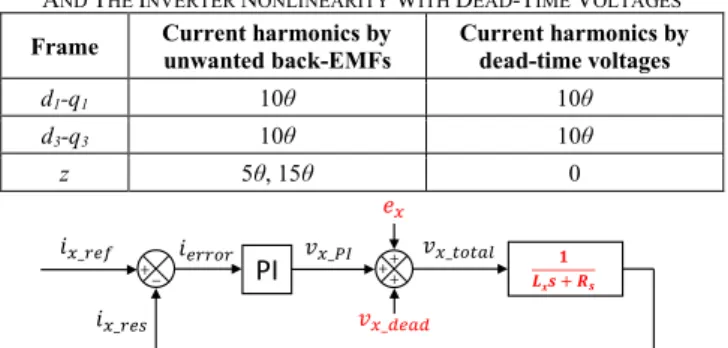
TABLE II
CURRENT HARMONICS CAUSED BY UNWANTED BACK-EMF HARMONICS
AND THE INVERTER NONLINEARITY WITH DEAD-TIME VOLTAGES
Frame Current harmonics by unwanted back-EMFs Current harmonics by dead-time voltages
d1-q1 10θ 10θ
d3-q3 10θ 10θ
z 5θ, 15θ 0
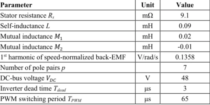
Fig. 2. The general control scheme of current ix under the impacts of the unwanted back-EMF harmonic ex and the inverter nonlinearity with dead-time voltage vx_dead without any compensations (x can be d1, q1, d3, q3 or z).
(
5 2 4)
1 9 1 11 sin 10
(
)
d1_dead dead v = − V + (11)(
5 2 4)
1
1 9 1 11 cos 10
(
)
q1_dead dead v = − V + + (12)(
5 2 4)
1 7 1 13 sin 10
(
)
d3_dead dead v = − V + (13)(
5 2 4)
1 3
1 7 1 13 cos 10
(
)
q3_dead dead v = − V + + (14) 0 z_dead v = (15)3) Current control scheme considering the impacts of
unwanted back-EMF harmonics and the inverter nonlinearity: According to (3), there are four d-q currents and
one zero-sequence current to be controlled in the 5-phase machine. Current ix (x can be d1, q1, d3, q3 or z) is controlled in the general scheme as described in Fig. 2 where a conventional proportional-integral (PI) controller is applied. Transfer function (1/(Lxs+Rs)) represents the fictitious machine model with their inductance and resistance in rotor reference frames. This control scheme considers the
unwanted back-EMF harmonic ex and the dead-time voltage
𝑣𝑥_𝑑𝑒𝑎𝑑 without any compensations.
B. Eliminations of low-frequency current harmonics
Theoretically, the current harmonics, generated by the unwanted back-EMF harmonics, can be eliminated by imposing estimated back-EMF harmonics in (5)-(9), called the back-EMF compensation. However, the correctness of the back-EMF compensation depends on parasitic time delay for compensations and on the original accuracy of phase measurements. In addition, current harmonics in rotor reference frames are also caused by the inverter nonlinearity with the dead-time voltages. Obviously, these harmonics cannot be perfectly eliminated by the back-EMF compensation.
The current harmonics have frequencies of 5θ, 10θ and 15θ in rotor reference frames as described in Table II. Their amplitudes depend on the back-EMF harmonic distribution, rotating speed, inverter dead time, switching period and DC-bus voltage. Due to the complexity of the real drives, these values need to be automatically learned in real time to correctly eliminate the current harmonics. Therefore, the general current control scheme with current harmonic eliminations is proposed in Fig. 3. Current ix (x can be d1, q1,
d3, q3 or z) is controlled by a PI controller with an adaptive
compensating voltage (𝑣𝑥_𝑐𝑜𝑚) generated by an ADALINE.
By using the compensating voltage ( 𝑣𝑥_𝑐𝑜𝑚 ), current
harmonics in rotor reference frames can be eliminated. This compensation is called the ADALINE compensation.
Fig. 3. The proposed control scheme of current ix with current harmonic eliminations by using the ADALINE compensation (𝑣𝑥_𝑐𝑜𝑚) and the back-EMF compensation (𝑒𝑥_𝑐𝑜𝑚) (x can be d1, q1, d3, q3 or z).
Fig. 4. The general structure of an ADALINE to generate compensating voltage (𝑣𝑥_𝑐𝑜𝑚) to eliminate current harmonics (x can be d1, q1, d3, q3 or z). From current harmonics described in Table II, the general structure of an ADALINE is proposed in Fig. 4. The
compensating voltage 𝑣𝑥_𝑐𝑜𝑚 is generally calculated from
several harmonics as described in (16).
_ 1 2 3 4
5 6
cos(5 ) sin(5 ) cos(10 ) sin(10 ) cos(15 ) sin(15 ) x com v k k k k k k = + + + + + (16)
where two weights k1 and k2 are associated with harmonic 5θ;
k3 and k4 are for harmonic 10θ; k5 and k6 are for harmonic 15θ. The presence of harmonics (5θ, 10θ and 15θ) in voltage
𝑣𝑥_𝑐𝑜𝑚 depends on the reference frame of the controlled
current as described in Table II. It means that the chosen harmonics depend on x where x can be d1, q1, d3, q3 or z. If x is d1, q1, d3 or q3, the ADALINE structure in Fig. 4 and (16)
has only weights (k3, k4) of harmonic 10θ. Meanwhile, if x is
z, weights (k1, k2) of harmonic 5θ and (k5, k6) of harmonic 15θ are chosen. Weights of a harmonic are updated by the Least Mean Square (LMS) rule with learning rate 𝜂, current error
𝑖𝑒𝑟𝑟𝑜𝑟 and the corresponding harmonic. According to LMS,
learning rate 𝜂 is small and close to zero to guarantee the convergence of weights.
It is noted that all current harmonics in rotor reference frames can be learned by the proposed ADALINE structure.
Thus, in Fig. 3, the ADALINE compensation with 𝑣𝑥_𝑐𝑜𝑚 can
be used without the back-EMF compensation using 𝑒𝑥_𝑐𝑜𝑚=
𝑒𝑥 in (5)-(9). However, the learning process of the ADALINE
can be faster when the ADALINE is combined with the back-EMF compensation. Hence, the back-back-EMF compensation
with 𝑒𝑥_𝑐𝑜𝑚 can be added to the control scheme in Fig. 3.
IV. NUMERICAL RESULTS
A. Parameters of the considered 5-phase PMSM drive
To verify the performance of the proposed strategy, the topology in Fig. 1 is simulated in MATLAB Simulink. Parameters of the 5-phase PMSM drive with the presence of six harmonics in the machine back-EMF are described in Fig. 5 and Table III. In fictitious machine FM1, besides the 1st
harmonic of the back-EMF, the 9th harmonic accounts for 5%
of the 1st harmonic. Meanwhile, FM2 contains the 3rd and 7th
harmonics with proportions of 10% and 6%, respectively.
The 5th and 15th harmonics in ZM are respectively equal to
1.1% and 4%. The VSIs are supplied by 𝑉𝐷𝐶= 48 𝑉.
Fig. 5. Harmonic spectrum and speed-normalized waveform of the considered back-EMF of phase A at 60 rad/s.
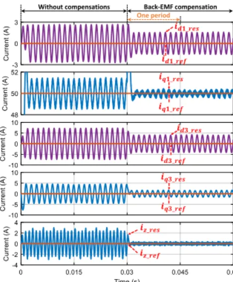
TABLE III
ELECTRICAL PARAMETERS OF THE CONSIDERED 5-PHASE PMSM DRIVE
Parameter Unit Value
Stator resistance Rs mΩ 9.1
Self-inductance L mH 0.09
Mutual inductance 𝑀1 mH 0.02
Mutual inductance 𝑀2 mH -0.01
1st harmonic of speed-normalized back-EMF V/rad/s 0.1358
Number of pole pairs p 7
DC-bus voltage 𝑉𝐷𝐶 V 48
Inverter dead time Tdead μs 3
PWM switching period TPWM μs 65
The three-level double PWM strategy in [2] is applied with a switching frequency of 15.3 kHz equivalent to a switching period TPWM of 65 μs. The inverter dead time Tdead is 3 μs.
B. Simulation results
To clearly see the effectiveness of the proposed strategy in eliminating current harmonics in rotor reference frames, currents (id1 and iq1) are controlled with references (𝑖𝑑1_𝑟𝑒𝑓=
0, 𝑖𝑞1_𝑟𝑒𝑓= 50 𝐴). The other currents (id3, iq3 and iz) are controlled with references (𝑖𝑑3_𝑟𝑒𝑓= 𝑖𝑞3_𝑟𝑒𝑓= 𝑖𝑧_𝑟𝑒𝑓= 0). As
a result, the expected phase currents are sinusoidal. In this numerical verification, there are 3 cases for the current control scheme in Fig. 3 to be investigated: only the
back-EMF compensation (𝑒𝑥_𝑐𝑜𝑚) ; only the ADALINE
compensation (𝑣𝑥_𝑐𝑜𝑚); both the ADALINE (𝑣𝑥_𝑐𝑜𝑚) and
back-EMF (𝑒𝑥_𝑐𝑜𝑚) compensations. In addition, dynamic
performances at variable speeds and current references for the last case will be verified.
(a)
(b) (c)
Fig. 6. Phase A current (a) and its harmonic spectrum before (b) and after (c) using only the back-EMF compensation at 60 rad/s.
PI ADALINE Updating laws 0 10 20 30 40 50 60 70 80 90 100 1 3 5 7 9 11 13 15 Per cen tag e (%) Harmonic components FM1 FM2 ZM 10% 1.1% 6% 5% 4%
Without compensations Back-EMF compensation One period 0 5 10 15 20 25 30 35 1 3 5 7 9 11 13 15 C u rr en t (A ) Harmonic components 100% 0.06% 0.4% 11.5% 4% 1.4% 3.5% 3.4% 0 5 10 15 20 25 30 35 1 3 5 7 9 11 13 15 C u rr en t (A ) Harmonic components 100% 0.05% 0.01%5.3%1.7% 1.4% 3.3% 0.06%
Fig. 7. Current control performances in rotor reference frames before and after using only the back-EMF compensation at 60 rad/s.
Fig. 8. The harmonic spectrum of the zero-sequence current 𝑖𝑧_𝑟𝑒𝑠 in rotor reference frames without any compensations at 60 rad/s.
1) Using only the back-EMF compensation: When the
control scheme in Fig. 3 applies only the back-EMF
compensation (𝑒𝑥_𝑐𝑜𝑚) to eliminate current harmonics, the
current of phase A and its harmonic spectrums are presented in Fig. 6. In Fig. 6a, after using the back-EMF compensation, the current of phase A is more sinusoidal. Indeed, the
harmonic spectrums of current iA in Figs. 6b and 6c show that
the high-order harmonics are reduced after the compensation,
but these harmonics still exist (7th harmonic decreases from
11.5% to 5.3%, for example).
Current control performances in rotor reference frames are presented in Fig. 7. Without any compensations, current responses (𝑖𝑑1_𝑟𝑒𝑠, 𝑖𝑞1_𝑟𝑒𝑠) and (𝑖𝑑3_𝑟𝑒𝑠, 𝑖𝑞3_𝑟𝑒𝑠) have harmonics
with frequencies 10θ as previously analyzed in section III. With the back-EMF compensation, the current harmonics in
(𝑖𝑑1_𝑟𝑒𝑠, 𝑖𝑞1_𝑟𝑒𝑠) and (𝑖𝑑3_𝑟𝑒𝑠, 𝑖𝑞3_𝑟𝑒𝑠) are not eliminated.
Meanwhile, the zero-sequence current 𝑖𝑧_𝑟𝑒𝑠 is rapidly
nullified with the back-EMF compensation. In Fig. 8, the
zero-sequence current response 𝑖𝑧_𝑟𝑒𝑠 without any
compensations has frequencies of 5θ and 10θ, that is in good accordance with the previous analyses (see Table II).
2) Using only the ADALINE compensation: When the
control scheme in Fig. 3 applies only the ADALINE compensation (𝑣𝑥_𝑐𝑜𝑚) , the current of phase A and its harmonic spectrums are presented in Fig. 9. It is noted that the phase current is almost perfectly sinusoidal after the compensation (Fig. 9a). The harmonic spectrums in Figs. 9b and 9c show that the fundamental current remains while the other harmonics are almost nullified. It is thanks to good current control performances in rotor reference frames as described in Fig. 10. It is concluded that the ADALINE compensation can eliminate all current harmonics in rotor reference frames. However, it takes about 3 operating periods (from 0.015 s to 0.06 s) to almost nullify harmonics 5θ and 10θ in the zero-sequence current 𝑖𝑧_𝑟𝑒𝑠. The reason is that four
weights for 5θ and 15θ are learned in this current while the other currents only require two weights for 10θ.
(a)
(b) (c)
Fig. 9. Phase A current (a) and its harmonic spectrum before (b) and after (c) using only the ADALINE compensation at 60 rad/s.
Fig. 10. Current control performances in rotor reference frames before and after using only the ADALINE compensation at 60 rad/s with η=0.00001, 0.00002, and 0.000005 for iz, idq1 and idq3, respectively.
Fig. 11. Phase A current (iA) and (id1, iq1) currents before and after using both the ADALINE and back-EMF compensations at 60 rad/s.
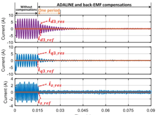
3) Using both the ADALINE and back-EMF compensations: When the control scheme in Fig. 3 applies
both the ADALINE and back-EMF compensations to eliminate current harmonics, the current of phase A and currents in rotor reference frames are presented in Figs. 11 and 12. It is noted that the combination can eliminate all current harmonics within one operating period (from 0.015 s to 0.03 s). The reason of the rapid elimination is that the use of the back-EMF compensation significantly reduces the current harmonics before the ADALINE compensation eliminates the rest of the harmonics. In other words, the convergence of ADALINE weights becomes faster with the same learning rate η as the previous case.
Without compensations Back-EMF compensation
One period 0 1 2 3 1 3 5 7 9 11 13 15 C u rr en t (A ) Harmonic components 0.3 A 2.33 A Without compensations ADALINE compensation One period 0 5 10 15 20 25 30 35 1 3 5 7 9 11 13 15 C u rr en t (A ) Harmonic components 100% 0.06% 0.4% 11.5% 4% 1.4% 3.5% 3.4% 0 5 10 15 20 25 30 35 1 3 5 7 9 11 13 15 C u rr en t (A) Harmonic components 100% 0.13%0.06%0.05%0%0.02%0.03%0.12% Without compensations ADALINE compensation One period Without compensations
ADALINE and Back-EMF compensations
Fig. 12. Currents (id3, iq3, iz) before and after using both the ADALINE and back-EMF compensations at 60 rad/s.
Fig. 13. Phase A current (iA) and (id1, iq1) currents using both the ADALINE and back-EMF compensations at 60, 120 and 240 rad/s.
Fig. 14. Currents (id3, iq3, iz) using both the ADALINE and back-EMF compensations at 60, 120 and 240 rad/s.
Fig. 15. Phase A current (iA) and (id1, iq1) currents using both the ADALINE and back-EMF compensations when the current reference (𝑖𝑞1_𝑟𝑒𝑓) changes from 50 to 25 A.
Additionally, the combination of the ADALINE and back-EMF compensations can improve the dynamic performances of the drive. Indeed, when the speed varies from 60 to 120 and 240 rad/s, all current response signals rapidly adapt to the changes of the rotating speed as shown in Figs. 13 and 14. At 240 rad/s, high-frequency components of
iz_res increase but not low-frequency current harmonics due to the PWM strategy. In addition, the decrease of current
reference (𝑖𝑞1_𝑟𝑒𝑓) from 50 to 25 A is properly responded by
the proposed control scheme as shown in Fig. 15.
V. CONCLUSION
This paper has proposed an option to eliminate current harmonics for a non-sinusoidal multiphase machine in an open-end winding configuration. Simple adaptive linear neural networks implemented in rotor reference frames can eliminate current harmonics caused by the unwanted back-EMF harmonics and the inverter nonlinearity. A combination between the ADALINE and back-EMF compensations can reduce the settling time. Thanks to this combination, the good dynamic performances are obtained when the rotating speed or current references suddenly change. The results show the effectiveness of the control method. This can be applied to an industrial drive due to its adaptivity and easy implementation.
ACKNOWLEDGMENT
This work has been achieved within the framework of CE2I project. CE2I is co-financed by European Union with the financial support of European Regional Development Fund (ERDF), French State and the French Region of Hauts-de-France.
REFERENCES
[1] F. Barrero and M. J. Duran, "Recent Advances in the Design, Modeling, and Control of Multiphase Machines Part I," IEEE Transactions on
Industrial Electronics, vol. 63, no. 1, pp. 449-458, 2016.
[2] T. J. D. S. Moraes, M. Trabelsi, H. Zahr, and E. Semail, "Homopolar Current's Copper Losses Analysis for Different Modulations in Open-End Winding Five-Phase Drives," in 2018 XIII International
Conference on Electrical Machines (ICEM), Alexandroupoli, Greece,
2018, pp. 1538-1544.
[3] J. Hwang and H. Wei, "The Current Harmonics Elimination Control Strategy for Six-Leg Three-Phase Permanent Magnet Synchronous Motor Drives," IEEE Transactions on Power Electronics, vol. 29, no. 6, pp. 3032-3040, 2014.
[4] D. T. Vu, N. K. Nguyen, E. Semail, and T. J. d. S. Moraes, "Control strategies for non-sinusoidal multiphase PMSM drives in faulty modes under constraints on copper losses and peak phase voltage," IET Electric
Power Applications, vol. 13, no. 11, pp. 1743-1752, 2019.
[5] E. Semail, X. Kestelyn, and A. Bouscayrol, "Right harmonic spectrum for the back-electromotive force of an n-phase synchronous motor," in
the 39th IEEE Industry Applications Conference, Seattle, WA, USA,
2004, vol. 1, pp. 71-78.
[6] G. Grandi and J. Loncarski, "Analysis of dead-time effects in multi-phase voltage source inverters," in 6th IET International Conference on
Power Electronics, Machines and Drives (PEMD 2012), 2012, pp. 1-6.
[7] K. Liu and Z. Q. Zhu, "Online Estimation of the Rotor Flux Linkage and Voltage-Source Inverter Nonlinearity in Permanent Magnet Synchronous Machine Drives," IEEE Transactions on Power
Electronics, vol. 29, no. 1, pp. 418-427, 2014.
[8] G. Liu, B. Chen, K. Wang, and X. Song, "Selective Current Harmonic Suppression for High-Speed PMSM Based on High-Precision Harmonic Detection Method," IEEE Transactions on Industrial Informatics, vol. 15, no. 6, pp. 3457-3468, 2019.
[9] T. Qiu, X. Wen, and F. Zhao, "Adaptive-Linear-Neuron-Based Dead-Time Effects Compensation Scheme for PMSM Drives," IEEE
Transactions on Power Electronics, vol. 31, no. 3, pp. 2530-2538, 2016.
[10] L. Wang, Z. Q. Zhu, H. Bin, and L. M. Gong, "Current Harmonics Suppression Strategy for PMSM with Non-Sinusoidal Back-EMF Based on Adaptive Linear Neuron Method," IEEE Transactions on Industrial
Electronics, pp. 1-1, 2019.
[11] G. Li, J. Hu, Y. Li, and J. Zhu, "An Improved Model Predictive Direct Torque Control Strategy for Reducing Harmonic Currents and Torque Ripples of Five-Phase Permanent Magnet Synchronous Motors," IEEE
Transactions on Industrial Electronics, vol. 66, no. 8, pp. 5820-5829,
2019.
[12] J. Karttunen, S. Kallio, P. Peltoniemi, and P. Silventoinen, "Current Harmonic Compensation in Dual Three-Phase PMSMs Using a Disturbance Observer," IEEE Transactions on Industrial Electronics, vol. 63, no. 1, pp. 583-594, 2016.
Without compensations
ADALINE and back-EMF compensations
One period
Speed 60 rad/s Speed 120 rad/s Speed 240 rad/s
Speed 60 rad/s Speed 120 rad/s Speed 240 rad/s