OPTIMISATION OF WIND TURBINE BLADE STRUCTURES USING A GENETIC ALGORITHM
ADAM CHEHOURI
Thesis submitted in the partial fulfillment of the requirements for the Doctor of Philosophy degree in Engineering
Chicoutimi, Québec, Canada
ABSTRACT
The current diminution of fossil-fuel reserves, stricter environmental guidelines and the world’s ever-growing energy needs have directed to the deployment of alternative renewable energy sources. Among the many renewable energies, wind energy is one of the most
promising and the fastest growing installed alternative-energy production technology.
In order to meet the production goals in the next few decades, both significant increases
in wind turbine installations and operability are required, while maintaining a profitable and
competitive energy cost. As the size of the wind turbine rotor increases, the structural
performance and durability requirements tend to become more challenging. In this sense,
solving the wind turbine design problem is an optimization problem where an optimal solution
is to be found under a set of design constraints and a specific target.
Seen the world evolution towards the renewable energies and the beginning of an
implementation of a local wind industry in Quebec, it becomes imperative to follow the
international trends in this industry. Therefore, it is necessary to supply the designers a suitable
decision tool for the study and design of optimal wind turbine blades.
The developed design tool is an open source code named winDesign which is capable
to perform structural analysis and design of composite blades for wind turbines under various
configurations in order to accelerate the preliminary design phase. The proposed tool is
capable to perform a Pareto optimization where optimal decisions need to be taken in the
presence of trade-offs between two conflicting objectives: the annual energy production and
the weight of the blade. For a given external blade shape, winDesign is able to determine an
optimal composite layup, chord and twist distributions which either minimizes blade mass or
TABLE OF CONTENTS
ABSTRACT
... ii
TABLE OF CONTENTS ... iii
LIST OF TABLES
... vi
LIST OF FIGURES
... vii
NOMENCLATURE AND ABBREVIATIONS ... ix
DEDICACE
... xii
INTRODUCTION
... 1
CHAPTER 1 : WIND TURBINE OPTIMIZATION: LITERATURE REVIEW
... 5
1.1
WIND ENERGY STATUS: GENERAL OVERVIEW
... 5
1.2
WIND TURBINE OPTIMIZATION: TIMELINE & COMPONENTS
... 7
1.3
SURVEY OF WTO STUDIES ... 8
1.3.1
REVIEW OF AIRFOIL SHAPE OPTIMIZATION IN WT DESIGN STUDIES ... 8
1.3.2
REVIEW OF WIND TURBINE BLADE OPTIMIZATION STUDIES ... 11
1.3.3 REVIEW OF WIND TURBINE PERFORMANCE OPTIMIZATION STUDIES ... 18
1.4
SUMMARY
... 25
CHAPTER 2 : MATHEMATICAL MODELS OF THE WIND TURBINE OPTIMIZATION PROBLEMS
.. 27
2.1
INTRODUCTION ... 27
2.2
OBJECTIVE FUNCTIONS ... 27
2.2.1
MINIMIZATION OF THE COST OF ENERGY ... 29
2.2.2 MAXIMIZATION OF THE ANNUAL ENERGY PRODUCTION ... 30
2.2.3 MINIMIZATION OF THE WIND BLADE MASS ... 30
2.2.4
MULTI-OBJECTIVE OPTIMIZATION FORMULATIONS ... 31
2.3
CONSTRAINTS APPLIED IN WIND TURBINE DESIGN PROBLEMS ... 32
2.3.1 GEOMETRICAL CONSTRAINTS ... 32
2.3.2
AERODYNAMIC CONSTRAINTS ... 35
2.3.3 PHYSICAL CONSTRAINTS ... 38
2.4
SUMMARY ... 44
CHAPTER 3 : THE PROPOSED GENETIC ALGORITHM
... 46
3.1
INTRODUCTION ... 46
3.2
COMPUTATIONAL ALGORITHMS APPLIED IN WTDP ... 46
3.2.2 GENETIC ALGORITHMS ... 50
3.3
PROPOSED CONSTRAINT-HANDLING TECHNIQUE (VCH) – ORIGINAL CONTRIBUTION54
3.3.1
MOTIF ... 54
3.3.2
CONSTRAINT-HANDLING TECHNIQUES – LITERATURE REVIEW ... 56
3.3.3
PROPOSED ‘VCH’ METHOD ... 59
3.3.4
NUMERICAL VALIDATION OF VCH ... 65
3.3.5
DISCUSSION OF THE VCH METHOD ... 78
3.4
PROPOSED SELECTION PROCESS USING CLUSTERING ANALYSIS – ORIGINAL
CONTRIBUTION
... 79
3.4.1
MOTIF ... 79
3.4.2
CLUSTERING ANALYSIS IN OPTIMIZATION ALGORITHMS
... 80
3.5
SUMMARY
... 100
CHAPTER 4 WIND TURBINE BLADE DESIGN AND OPTIMIZATION TOOLS ... 102
4.1
INTRODUCTION
... 102
4.2
OVERVIEW OF WIND TURBINE ROTOR AERODYNAMICS
... 102
4.3
WIND TURBINE DESIGN NUMERICAL TOOLS ... 110
4.3.1
AIRFOIL PREPARATION CODES
... 110
4.3.2
ROTOR PERFORMANCE MODELS
... 111
4.3.3
AERODYNAMIC LOADS SOLVERS ... 112
4.3.4
GEOMETRIC DESCRIPTION
... 113
4.4
WIND TURBINE STRUCTURE DESIGN SOFTWARE
... 113
4.4.1
STATIC TOOLS ... 114
4.4.2
DYNAMIC TOOLS
... 115
4.5
CO-BLADE TOOL
... 116
4.5.1
CO-BLADE DESIGN TOOL ... 116
4.5.2
CLASSICAL LAMINATION THEORY (CLT) ... 119
4.6
SUMMARY
... 125
CHAPTER 5 PROPOSED WIND TURBINE BLADE DESIGN TOOL – ‘WINDESIGN’ ... 126
5.2.3
MULTI-OBJECTIVE EVOLUTIONARY ALGORITHMS ... 130
5.3
WINDESIGN – GENERAL STRUCTURE ... 131
5.3.1
MONOOBJECTIVE OPTIMIZATION – WINDESIGN ... 131
5.3.2
MULTIOBJECTIVE OPTIMIZATION – WINDESIGN ... 133
5.4
SUMMARY
... 135
CHAPTER 6 CONCLUSION & FUTURE WORKS
... 138
6.1
VCH METHOD: CHALLENGES AHEAD & UPCOMING SUCCESS ... 138
6.2
KGA TECHNIQUE: FEASIBLE SCIENTIFC IMPACT
... 141
6.3
WINDESIGN TOOL: MOVING TOWARDS WINDESIGN 2.0 ... 143
6.3.1
AIM & FOCUS ... 143
6.3.2
CURRENT TRENDS & FUTURE CHALLENGES
... 144
ANNEX
... 167
ANNEX A: INPUTS FOR WINDESIGN ... 167
ANNEX B: WINDESIGN LAYOUT
... 172
LIST OF TABLES
TABLE 1 : OPTIMAL RESULTS FOR HIMMELBLAU’S NONLINEAR PROBLEM. ... 69
TABLE 2 : STATISTICAL RESULTS FOR HIMMELBLAU’S NONLINEAR PROBLEM. ... 69
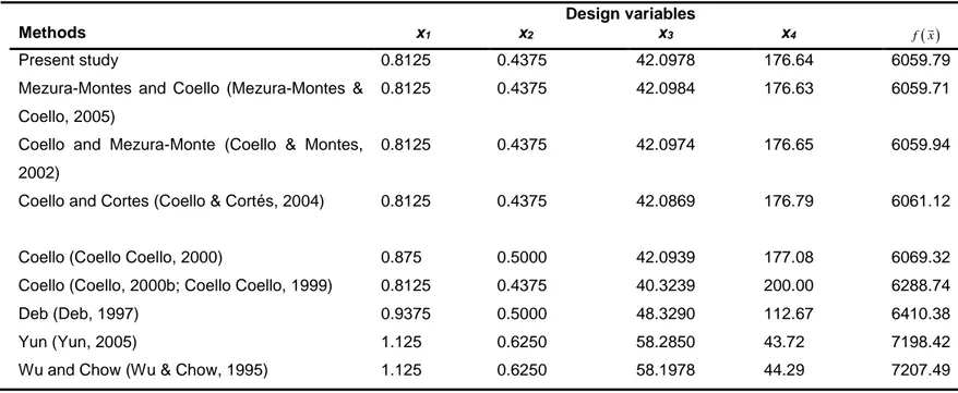
TABLE 3 : OPTIMAL RESULTS FOR SPRING DESIGN PROBLEM. ... 71
TABLE 4 : STATISTICAL RESULTS FOR SPRING DESIGN PROBLEM. ... 71
TABLE 5 : OPTIMAL RESULTS FOR PRESSURE VESSEL DESIGN PROBLEM. ... 73
TABLE 6 : STATISTICAL RESULTS FOR PRESSURE VESSEL DESIGN PROBLEM. ... 74
TABLE 7 : OPTIMAL RESULTS FOR WELDED BEAM DESIGN PROBLEM. ... 77
TABLE 8 : STATISTICAL RESULTS FOR WELDED BEAM DESIGN PROBLEM. ... 77
TABLE 9 : SUMMARY OF THE TEST FUNCTIONS. ... 93
TABLE 10 : COMPARISON OF STATISTICAL RESULTS OF 4 ALGORITHMS FOR TEST PROBLEMS 1–7 OF DIMENSIONS D=10. ... 95
TABLE 11 : COMPARISON OF STATISTICAL RESULTS OF 4 ALGORITHMS FOR TEST PROBLEMS 1–7 OF DIMENSIONS D=20. ... 97
TABLE 12 : P-VALUES FOR WILCOXON TEST FOR BENCHMARK FUNCTION 7. ... 100
TABLE 13 : DESIGN VARIABLES FOR CO-BLADE. ... 118
LIST OF FIGURES
FIGURE 1 : NUMBER OF PUBLISHED DOCUMENTS ON WIND TURBINE DESIGN IN THE LAST
40 YEARS (REPRODUCED FROM SCOPUS DATABASE). ... 7
FIGURE 2 : FLOWCHART OF GIGUÈRE ET SELIG (GIGUERE & SELIG, 2000) (REPRODUCED FROM (GIGUERE & SELIG, 2000)). ... 12
FIGURE 3 : NUMERICAL ALGORITHM APPLIED BY FUGLSANG AND MADSEN (P. FUGLSANG & MADSEN, 1999). ... 13
FIGURE 4 : BLADE MATERIAL OF CHEN ET AL. (J. CHEN ET AL., 2013) (REPRODUCED FROM (J. CHEN ET AL., 2013)). ... 18
FIGURE 5 : DESIGN TOOL OF FUGLSANG ET AL. (PETER FUGLSANG ET AL., 2002) (REPRODUCED FROM (PETER FUGLSANG ET AL., 2002)). ... 21
FIGURE 6 : FLOWCHART OF THE OPTIMIZATION SCHEME OF MAKI ET AL. (MAKI ET AL., 2012) (REPRODUCED FROM (MAKI ET AL., 2012)). ... 22
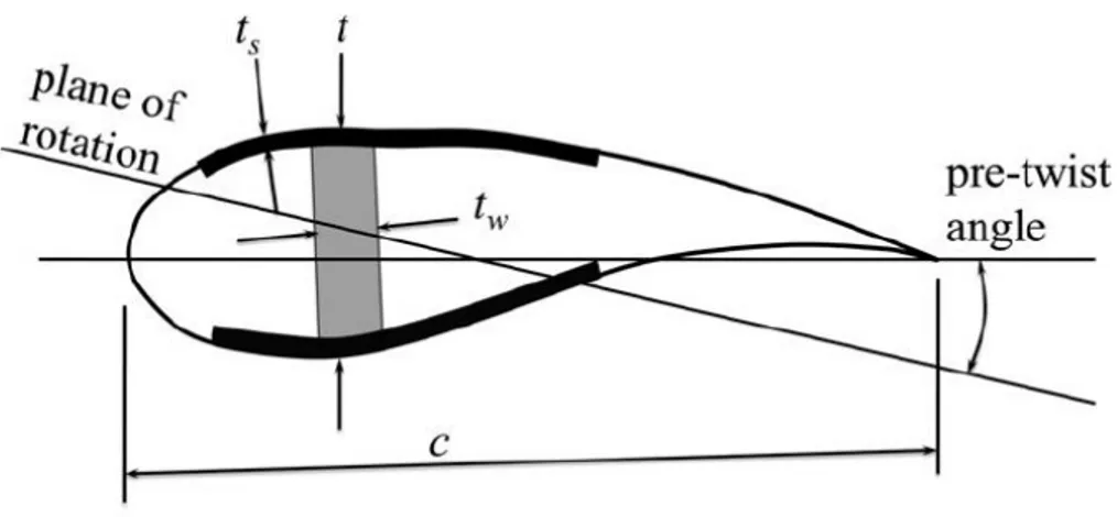
FIGURE 7 : BLADE SECTION DIAGRAM (SOURCE (MAKI ET AL., 2012)). ... 36
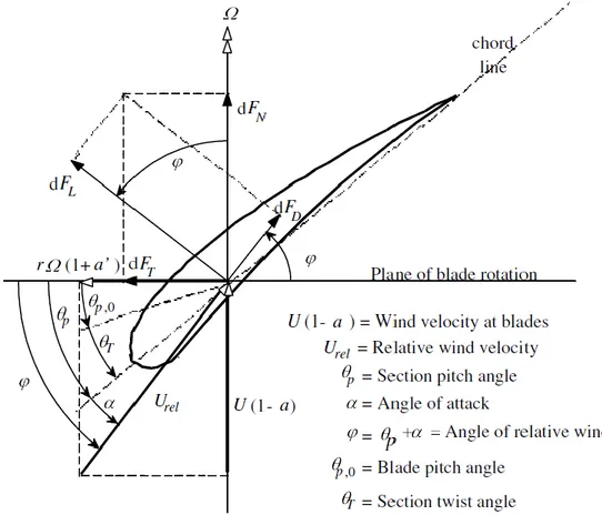
FIGURE 8 : FORCES APPLIED ON A WIND TURBINE BLADE ELEMENT (SOURCE (MANWELL, MCGOWAN, & ROGERS, 2010)). ... 41
FIGURE 9 : CLASSIFICATION OF META-HEURISTIC ALGORITHMS (SOURCE (DRÉO, 2007)). ... 48
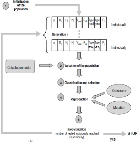
FIGURE 10 : PSEUDO-CODE OF A STANDARD GENETIC ALGORITHM. ... 51
FIGURE 11 : OPTIMIZATION SCHEME USING A GENETIC ALGORITHM (SOURCE (T DIVEUX ET AL., 2001)). ... 53
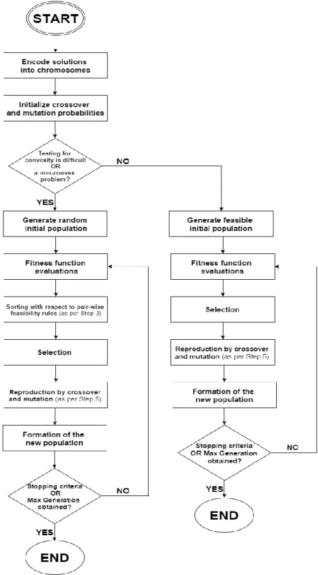
FIGURE 12 : COMPLETE FLOWCHART OF THE PROPOSED GA. ... 66
FIGURE 13 : AVERAGE CONSTRAINT-HANDLING (CV) AND BEST FITNESS FUNCTION OBTAINED WITH THE PROPOSED VCH METHOD FOR THE WELDED BEAM DESIGN PROBLEM... 79
FIGURE 14 : FUNCTION CODE OF THE MEMBERSHIP PROBABILITY VECTOR... 89
FIGURE 15 : FLOWCHART OF THE PROPOSED KGAF TECHNIQUE. ... 90
FIGURE 17 : ORIENTATION OF THE BLADE AXE SYSTEMS (DANNY SALE, 2012). ... 117
FIGURE 18 : COMPOSITE BEAM BENDING WITH LAYER NUMBERING. ... 121
FIGURE 19 : COORDINATE SYSTEMS USED IN THE LAMINATED PLATE THEORY... 123
FIGURE 20 : NUMBER OF PUBLISHED DOCUMENTS ON MULTI-OBJECTIVE EVOLUTIONARY
ALGORITHMS. ... 127
FIGURE 21 : PARETO-FRONT FOR THE GIVEN NUMERICAL EXAMPLE (ANNEX A, EQ. 5.5)
... 135
NOMENCLATURE AND ABBREVIATIONS
a Induction factor
ACO Ant Colony Optimization
AEP Annual Energy Production
AoA Angle of attack (º)
as Speed of sound (m/s)
BEM Blade Element Momentum theory
bm Buckling margin
Ccomp Component cost ($)
CanWEA Canadian Wind Energy Association
CD Drag coefficient
CL Lift coefficient
CL/CD Lift-to-drag ratio
CP Rotor power coefficient
CP Pressure coefficient
Cmc Pitching moment coefficient
CWT Total wind turbine cost
CHT Constraint-Handling Technique CFD Computational Fluid Dynamics CLT Classical Lamination Theory CoE Cost-of-Energy
DB Davies-Bouldin validity index DE Differential Evolution
DES Detached Eddy Simulation DNS Direct Navier-Stokes
𝑫𝐑 Diameter of the wind turbine rotor (m)
EA Evolutionary Algorithms
EAP Annual Energy Production (kWh) ECGA Extended Compact Genetic Algorithm
ES Evolutionary Strategy
f(V) Wind speed distribution
FD Drag force applied on the blade element (N)
FL Lifting force applied on the blade element (N)
Fn Axial force applied on the blade element (N)
FWT Calibration factor for the cost model FSF Fatigue Safety Factor
𝒈𝒊(𝒙⃗⃗ ) Inequality constraints
GA Genetic Algorithm
GBA Gradient-Based Methods 𝒉𝒊(𝒙⃗⃗ ) Equality constraints
HAWT Horizontal Axis Wind Turbine
IEC International Electrotechnical Commission
K Number of clusters
KGA K-means Genetic Selection
KGAf K-means Genetic Selection process with a fixed number of clusters KGAo-DB K-means Genetic Selection using the Davies-Bouldin validity index KGAo-S K-means Genetic Selection using the Silhouette validity index KMA K-means Algorithm
LES Large Eddy Simulation
LU Lebanese University
M Shaft torque applied on the blade element (N.m)
Mmax Maximum permissible shaft torque on a blade element (N.m)
MN Mach number
MNtip Mach number at the wing tip
MOOP Multi-objective Optimization Problem
MOEA Multi-objective Evolutionary Algorithm
N Number of revolutions per minute (rpm) NCGA Neighborhood Cultivation Genetic Algorithm
Ncross Number of crossover-ed individuals during the evolution process Nelite Number of elite individuals selected during the evolution process
Nmt Number of mutated individuals during the evolution process
NPGA Niched Pareto Genetic Algorithm NREL National Renewable Energy Laboratory NSGA Non-dominated Sorting Genetic Algorithm n Number of revolutions per second (rps)
P(V) Power curve
PAES Pareto Archived Evolution Strategy
Sf Safety gap factor between ω1f and ω3p
SLP Sequential Linear Programming
SPEA Strength Pareto Evolutionary Algorithm SQP Sequential Quadratic Programing SR Swept area of the rotor (m2)
T Thrust generated by a blade element (N)
Tmax Maximum permissible thrust on a blade element (N)
U Wind velocity or wind velocity spectrum (m/s) UQAC Université du Québec à Chicoutimi
UQAR Université du Québec à Rimouski 𝑽𝐭𝐢𝐩 Velocity of the blade tip (m/s)
𝑽𝒕𝐢𝐩,𝐦𝐚𝐱 Maximum blade tip velocity (m/s)
VCH Violation Constraint-Handling technique VEGA Vector-Evaluated Genetic Algorithm
WT Wind Turbine
WTDP Wind Turbine Design Problems WTO Wind Turbine Optimization 𝒙
⃗⃗ Vector of design variables 𝒙
⃗⃗ 𝒍𝒐𝒘𝒆𝒓 Lower bound vector of the design variables
𝒙
⃗⃗ 𝒖𝒑𝒑𝒆𝒓 Upper bound vector of the design variables
λ Tip speed ratio
Δ Tolerance between two design variables of the same nature θ Angle between the relative flow and the chord line
𝝈 Normal stress generated on a blade element (N.m-2)
ρ Density (kg/m3)
ϭult Ultimate permissible stress (N.m-2)
ω Natural frequency (Hz)
ω1f First blade flap natural frequency at rotor rated speed (Hz)
ω3p Three-per-rev frequency at rotor rated speed 𝝎∗ Target frequency of the rotor at rated speed
ωlower Lower bound of the natural frequency of the blade (Hz)
ωupper Upper bound of the natural frequency of the blade (Hz)
ɛ50 Strain at 50-year extreme conditions
ɤ Safety factor on the strain ɛcr Critical buckling strain
ɛult Ultimate strain
DEDICATION
This thesis is the product of a four-year journey, during which numerous life lessons were
acquired. This short dedication does not and will not recognize the many individuals throughout
this journey; nonetheless it is a brave attempt to do so.
It all started at the Faculty of Engineering of the Lebanese University in Beirut, fall of 2011, inside Professor Mazen Ghandour’s office where we both had a long discussion about a numerical simulation study of a VAWT which I conducted earlier in the summer of 2011. Little
did I know that this meeting would be a milestone event, after which I was introduced to Hussein
Ibrahim (Ph.D) and Professor Rafic Younes. During my final year of undergraduate studies and
under the supervision of Rafic Younes, we conducted a comparative study of the performance
of textile composite materials wind turbine blades. During my two-months internship in Gaspé and Rimouski, I had the pleasure to discover Hussein Ibrahim’s work, his area of expertise and his personal journey throughout his doctoral studies. At the same time, my internship in Quebec
exposed me to the growing market of renewable energy, particularly wind energy, and hybrid
storage. I recall meeting Professor Adrian Ilinca for the first time in the cafeteria of the UQAR.
No promises were given at the time, but together we spoke about the possibility of a doctoral
project together.
Fast forward a year later, dragging two suits in both hands and carrying a laptop in my
backpack, I set forth towards a town 200 km north of Quebec City by the name of Chicoutimi
(Saguenay). I can still recall arriving in January 2014 and giving instructions to the taxi driver
to transport me towards the LIMA AMIL laboratory at the Université du Québec à Chicoutimi. I
was welcomed by Elizabeth Crook and Professor Jean Perron. Boiling emotions run through
my body as I recall my first few days and weeks in Chicoutimi.
The outcome of that year was a complete review of performance optimization techniques
applied in the design of wind turbines. Remaining hopeful paid-off.
Highly motivated to tackle the trials of my second year, I successfully completed my
doctoral exam with the conclusion that our doctoral research required a minor adjustment. My
mindset was to strive for success and greatness. The product of my second year was a novel
technique for constraint-handling in genetic algorithms. Developing optimization algorithms
became an obsession.
Going into my third year, I was dealing with a personal crisis following a series of events
and incorrect choices. It was clear from the beginning of year 2016 that it would be one filled
with obstacles of a different taste and magnitude. I recall sitting with Professor Perron, reassuring me that this is a normal and necessary state of mind called ‘la traversée du désert’. I would be a hypocrite to claim that I overcame my obstacles all alone, with ease and no
negative impact on productivity. Adel Chehouri, Hussein Ibrahim, Ahmad Chamseddine, Ibrahim Bitar and Zein Saleh, you all have superhero powers, word can’t express how grateful I am to have your support, guidance and mentoring. Finding my way out of the desert, breaking
through many constraints and in search of a work-life balance, I gathered my thoughts and set
forth a higher objective: silence the doubters and strive for success. Working in parallel with
Rafic Younes and my supervisors, we pushed forward the research project and set a plan for
the remaining calendar.
September 2016, I reverted to my childhood passion and love: general aviation – a reunion 9 years in the making. I had two priorities for the year of 2016-2017: complete my PhD studies and receive my private pilot license. I label this year as ‘Trusting the Process’. At the final stage of my doctoral studies, a Transport Canada private pilot license in one hand and a
solid curriculum vitae in the other, I was ready to begin scripting my next chapter.
There is something about the month of May, great things always seem to occur for me in May. With the same suits cases, same laptop in my backpack, Ahmad Chamseddine’s SUV
filled with boxes, I departed Saguenay in the direction of my hometown, Montreal – and began my career journey with Hatch.
To my Brother, Parents, Sister… To Eleanor Barbara Chehouri…
Bruce Wayne: I wanted to save Gotham. I failed.
Alfred Pennyworth: Why do we fall sir? So that we can learn to pick ourselves up.
¸
INTRODUCTION
The depletion of fossil-fuel reserves, stricter environmental regulations and the world’s ever-growing energy needs have steered to the deployment of alternative renewable energy
sources. Among the various renewable energy alternatives, wind energy is one of the most
promising and the fastest growing installed alternative-energy production technology (M.
Grujicic et al., 2010).
CanWEA reports that the province of Quebec is Canada’s second-biggest market for wind power with 3510 MW of installed capacity. Their 2030 energy policy aims to increase
renewable energies by 25 % and decrease fossil fuel by 40 % over the next year. In fact, it is anticipated that by 2025, at least 20% of Canada’s electricity demand will be met by various onshore and offshore wind-farms (Lafrance, Nolet, & Cote). Achieving this vision will deliver
huge paybacks:
• Generating $79 billion in Canadian wind energy investments, in a $1.8 trillion global wind industry.
• Creating at least 52,000 full-time jobs.
• 55,000 MW of clean energy injected into the electrical grids. • Cutting Canada’s annual greenhouse gas emissions by 17 %.
In order to meet the 20% production goal in the next 10 years, both significant increases
in wind turbine installations (offshore and inshore farms) and an increase in wind turbine
operability are required, while maintaining a profitable and competitive energy cost (Lindenberg, Smith, & O’Dell, 2008). To reduce the cost of energy (typically expressed in $/kWh), commercial wind turbines have grown considerably in size over the last 30 years. This
As the size of the wind turbine rotor increases, the structural performance and durability
requirements tend to become more challenging. Presently it is still unclear the ultimate rotor
diameter which can be attained with the current material and manufacturing technologies (M.
Grujicic et al., 2010). In addition to the aforementioned structural performance and durability
requirements the wind turbine has to meet with the evolving energy policies, international
treaties, legislations and regulations set by the governments (Saidur, Islam, Rahim, & Solangi,
2010).
In this sense, solving the wind turbine design problem is an optimization problem where
an optimal solution is to be found under a set of design constraints and a specific target. Seen
the world evolution towards the renewable energies and the beginning of an implementation of
a local wind industry in Quebec, it becomes imperative to follow the international trends
concerning the integration of composite material in this industry. Therefore, it is necessary to
supply the designers a suitable decision tool for the study and design of optimal wind turbine
blades
As reported in Seminar 1 and 2, the primarily goal of our research is to propose a wind
turbine design tool with an interactive interface. It is important to mention that throughout our
doctoral research; the topic has evolved from an early focus towards its current form. Initially,
the intention was oriented towards the study of textile composites inside the structure of the
wind turbine blades. After completing a literature review on the optimization techniques applied
in WTOP, we concluded that our efforts should be oriented towards building an optimization
tool capable of handling multiple technical specifications. The developed design tool is an open
source code named winDesign which is capable to perform:
• Structural analysis and design of composite blades for wind turbines under various configurations in order to accelerate the preliminary design phase.
• The proposed winDesign tool should perform a Pareto optimization where optimal decisions need to be taken in the presence of trade-offs between two conflicting
objectives: AEP and the weight of the blade.
• For a given external blade shape, winDesign should determine an optimal composite layup, chord and twist distributions which either minimizes blade mass or maximizes
the annual energy production while simultaneously satisfying design constraints.
Admitted into the PhD in engineering program at UQAC in January 2014, this report
includes 10 trimesters of research studies on the subject of: optimization of the structure of
wind turbine blades using a genetic algorithm, under the supervision of:
1. Professor Jean Perron, UQAC: doctoral advisor/director
2. Professor Rafic Younes, LU: co-director and main scientific advisor
3. Professor Adrian Ilinca, UQAR: co-director of research
This dissertation is divided into 6 main chapters in which the following key elements are
discussed:
• A literature review of the most relevant wind turbine optimization studies is presented in chapter 1.
• Survey of the mathematical models applied in wind turbine performance optimization problems are presented in chapter 2.
• Two main original contributions for the proposed genetic algorithm of winDesign are discussed in this chapter. In section 3.3, a new constraint-handling technique named ‘Violation Constraint-Handling’ (VCH) is introduced. Likewise, section 3.4 presents a selection process mechanism using clustering analysis for genetic search called KGA. • In chapter 4, we will focus on existing wind turbine blade design codes, tools and
• The newly proposed winDesign graphical tool which incorporates the novel VCH and KGA techniques, is presented in chapter 5 with results from both mono-objective and
multi-objective numerical simulations.
• Finally, we terminate this dissertation with chapter 6, where a detailed discussion, conclusion and a projection of future works are presented.
CHAPTER 1
WIND TURBINE OPTIMIZATION: LITERATURE REVIEW
1.1 WINDENERGYSTATUS:GENERALOVERVIEW
Since early recorded history, humans have harnessed the kinetic energy of the wind. Wind
energy propelled boats along the Nile River as early as 5000 B.C. By 200 B.C., windmills in
China and Persia were pumping water, while vertical-axis windmills were grinding grain in the
Middle East.
With the development of electrical power, wind power found new applications in residential
lighting away from power plants. Throughout the 20th century, small wind turbine plants, suitable for farms and homes, along with larger wind farms connected to the grid were
developed.
In the 1980’s, while wind energy’s growth in North America was slow, wind energy in Europe expanded in part due to environmental concerns in response to scientific studies about
global climate change and global warming.
Today, wind power operates in various size range, from small turbines for isolated
residences to large hundred of megawatt-size wind farms that generate electricity to the
transmission grid.
As of the 21st century began, fossil fuel is still relatively inexpensive, but rising concerns over global warming and the eventual fossil fuel depletion has led to an expansion of interest
in renewable energy. Since wind power can only generate electricity rather than liquid fuels, it
cannot substitute for petroleum in transportation in the immediate future.
Ibrahim, Younès, Basbous, Ilinca, & Dimitrova, 2011; Hussein Ibrahim, Younès, Ilinca,
Dimitrova, & Perron, 2010; Hussein Ibrahim et al., 2011). In 2016, renewable energy sources
currently provided 19% of the total Canadian energy demand with 96 636 MW of installed
capacities. Hydropower is the most important renewable energy source in Canada, accounting for more than 59% of Canada’s electricity generation. In fact, Canada ranks as the second largest producer of hydroelectricity in the world (Adib et al., 2016).
Canada has large areas with excellent wind resources and therefore a potential for wind
turbine projects. Much like other sites, the highest potential areas are offshore and along the
coastlines. Until now, no offshore wind farms have been built in Canada. In 2016, Canada
added 1.5 GW for a total of 11.2 GW, ranking sixth globally for additions and seventh for total capacity. The installed wind power capacity was enough to supply 5% of Canada’s electricity demand.
The 2030 energy policy set by CanWEA aims to increase renewable energies by 25 %
and decrease fossil fuel by 40 % over the next year. In fact, it is anticipated that by 2025, at least 20% of Canada’s electricity demand will be met by various onshore and offshore wind-farms (Lafrance et al.). In order to meet the 20% production goal in the next 10 years, both
significant increases in wind turbine installations (offshore and inshore farms) and an increase
in wind turbine operability are required, while maintaining a profitable and competitive energy
cost (Lindenberg et al., 2008). To reduce the cost of energy (typically expressed in $/kWh),
commercial wind turbines have grown considerably in size over the last 30 years. As the size
of the wind turbine rotor increases, the structural performance and durability requirements tend
to become more challenging. In addition to the aforementioned structural performance and
durability requirements the wind turbine has to meet with the evolving energy policies,
international treaties, legislations and regulations set by the governments (Saidur et al., 2010).
In this sense, solving the wind turbine design problem is an optimization problem where
Therefore, our literature review search must begin from a survey of wind turbine optimization
studies.
1.2 WIND TURBINE OPTIMIZATION: TIMELINE & COMPONENTS
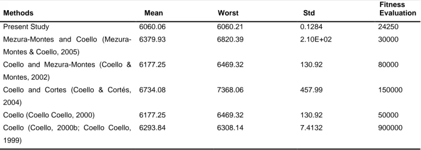
The rapid growth in the number of research publications on wind turbine design
optimization since 1990 highlights the status of the field of WTO (Figure 1). In the past, some
authors have compared the impact of different optimization objectives on the quality of the
solution, others have reviewed the optimization algorithms, energy policies, economics,
environmental impacts of wind turbines but numerous researchers have proposed different
optimization methodologies and resolution strategies.
None of the manuscripts in the literature reviewed the techniques of performance
optimization of wind turbines. Therefore, the purpose of our published literature review in the
journal of Applied Energy was to review the optimization techniques applied to wind turbines.
0 2000 4000 6000 8000 10000 12000 14000 16000 1990 1992 1994 1996 1998 2000 2002 2004 2006 2008 2010 2012 2014 2016 Nu m b er of D oc u m en ts Year
1.3 SURVEY OF WIND TURBINE OPTIMIZATION STUDIES
We begin by examining the most relevant wind turbine performance optimization studies
conducted in the last 20 years. The reader is invited to refer to ‘review of performance optimization techniques applied to wind turbines’ for a complete overview of the performance optimization techniques applied to horizontal wind turbines.
1.3.1 REVIEW OF AIRFOIL SHAPE OPTIMIZATION IN WIND TURBINE DESIGN STUDIES
The design of new airfoils families suited for wind turbines is an imperative field of
research for the development of the wind energy industry (Björck, 1990; Peter Fuglsang, Bak,
Gaunaa, & Antoniou, 2004; J. L. Tangler & Somers, 1995; Timmer & Van Rooij, 2003). During
the last two decades, a series of airfoil design guidelines have been proposed by national
energy laboratories and international commissions (Dutton, Bonnet, Hogg, & Lleong, 2010; P
Fuglsang, 2002; Veritas, 2002). According to Ju and Zhang (Ju & Zhang, 2012), a desirable
wind turbine airfoil should satisfy the following aerodynamic requirements:
1. High lift-to-drag ratio (CL/CD) and high lift coefficient (CL)
2. Good performance during stochastic behavior of wind speed
3. Low sensitivity to leading edge roughness
A reduced sensitivity to the roughness (mainly leading edge roughness) means that the
wind turbine blade should be efficient in dirty conditions (Sagol, Reggio, & Ilinca, 2013). In
addition, the moment coefficient cannot be too high because this will increase blade torsion. In
contrast, in pitch regulated wind turbine, a low moment coefficient causes a reduction in control
forces. Because of wind gusts, the local angle of attack can suddenly change and be in
pre-stall or pre-stall zones (F. Grasso, 2011). Hence, the selection of the airfoil families is crucial in the
approaches in wind turbine airfoil shape optimization. Below, we will review the most relevant
airfoil shape optimization studies in the last two decades.
The desirable airfoil characteristics for wind turbine blades can be divided into two main
categories: structural and aerodynamic. Throughout the wind turbine blade length distribution,
different physical characteristics are key at the root, mid and tip. The root is mainly designed
with regards to structural concerns, whereas the tip is determined for aerodynamic
considerations (Bizzarrini, Grasso, & Coiro, 2011). The most significant structural parameters
are the maximum airfoil thickness and its chord-wise location (F. Grasso, 2011). The airfoil
thickness must be able to provide the required blade strength and stiffness. The location of the
maximum thickness along the chord ensures a better penetration of the spar inside the airfoil
sections. As for the tip region, the main aerodynamic parameter is the lift-to-drag ratio. This
ratio is mainly related to the stall behavior and the CL,max of the airfoil. A relatively high value of
the lift coefficient allows the designer to reduce the chord and consequently the loads in parked
conditions at high speeds. A lower chord near the tip also reduces the weight of the blade and
the amplitude of fluctuating load resulting from wind gusts (F. Grasso, 2011).
Burger and Hartfield (Burger & Hartfield, 2006) examined the feasibility of using the
combination of the vortex lattice method with a genetic algorithm to optimize the aerodynamic
performance of a horizontal axis wind turbine blade.
Li et al. (J. Y. Li, Li, Gao, & Huang, 2010) presented an improved optimization technique
using response surface methods to improve the lift-to-drag ratio for 2D wind turbine airfoils.
In (Bizzarrini et al., 2011; F. Grasso, 2011; Francesco Grasso, 2012) the authors focused
on the airfoil design at the tip region of the blade using numerical models. Grasso (Francesco
with each other, Grasso combined both objectives using a weighted linear combination (Eq.
1.1):
min 𝑓(𝑥 ) = 𝑘 (𝐿
𝐷) + (1 − 𝑘)𝐼𝑥𝑥 [1.1]
where k is a weighting parameter varying between 0 and 1, L/D the ratio of lift over drag,
Ixx is the sectional moment of resistance.
In recent years, blunt trailing edge or flatback airfoils have been suggested for the
inboard regions of large wind-turbine blades since they provide some structural and
aerodynamic performance advantages (ASHWILL, 2003; Jackson, Zuteck, Van Dam,
Standish, & Berry, 2005; Standish & Van Dam, 2003; Van Rooij & Timmer, 2003). Chen et al.
(X. Chen & R. Agarwal, 2012) apply a multi-objective genetic algorithm code for the optimal
design of flatback series. The two objectives were the maximum lift coefficient and maximum
lift-to-drag ratio. It was shown that the multi-objective scheme generated flatback airfoils with
better performances than those obtained using a single objective GA algorithm in (X. Chen &
Agarwal, 2010; X. M. Chen & R. Agarwal, 2012).
Ribeiro et al. (Ribeiro, Awruch, & Gomes, 2012) coupled a RANS equation in steady
state with one equation turbulence model and an optimization algorithm. Single and
multi-objective genetic algorithms are employed, and artificial neural networks were used as a
surrogate model to generate optimal airfoil shapes.
Jeong et al. (Jeong, Park, Jun, Song, & Lee, 2012) minimized the fluctuation of the
unsteady aerodynamic load under turbulent wind condition. It was noted that the out-of-plane
fluctuating unsteady aerodynamic load is more significant than the in-plane loads for structural
fatigue of the blade. The rms of the out-of-plane bending moment was reduced by about 20%
Ju et al. (Ju & Zhang, 2012) developed a robust design optimization (RDO) for wind
turbine airfoils by maximizing the CL/CD and CL of the airfoil along with a sensitivity minimization
of the roughness at the leading edge associated with the geometry profile uncertainty.
1.3.2 REVIEW OF WIND TURBINE BLADE OPTIMIZATION STUDIES
In this section, we examine the most relevant wind turbine blade optimization studies
conducted in the last 20 years.
One of the early studies was performed in 1996 by Selig and Coverstone-Carroll (M. S.
Selig & Coverstone-Carroll, 1996). They examined the maximization of energy production with
no or few constraints on the loads.
A year later, Giguère et Selig (Giguere & Selig, 2000) presented a multi-disciplinary
optimization platform for the optimal blade geometry of HAWT’s (refer to
Figure 2). A
combination of two objectives was used to obtain a trade-off curve, captured by the use of asharing function. Only the structure of the blade was considered but the effects of the rotor on
other components are represented in the cost model. These components include the hub,
drivetrain, controller, nacelle and the tower. The cost of each component is modeled using the
relative approach where the cost is obtained from a baseline model. In addition, the cost of
each component is correlated with the corresponding design variables and normalized with the
value from the baseline (except for the controller, which does not rely on baseline cost).
The following procedure was used to estimate the blade weight and resulting cost, as
indicated in Figure 2.
1. The flap-bending load at each segment is determined from the thrust distribution for
2. The required moment of inertia of each segment is calculated using the flap-bending
load to counterpart a prescribed stress level σp (one for the hub and skin and another
for the spar) along the blade.
3. The required hub and spar thickness is found, neglecting the inertia of the skin and
spar and that of the shear webs about their own axis of rotation.
4. The required number of plies from the skin thickness distribution is chosen.
5. Calculation of the tip deflection.
6. The cross-sectional area at each segment is calculated.
7. The volume of the material is estimated from a linear extrapolation of the cross
sectional-area.
8. Finally, the blade weight is estimated from the number of blades N, volume MVB and
density ρB.
Figure 2 : Flowchart of Giguère et Selig (Giguere & Selig, 2000) (Reproduced from (Giguere & Selig, 2000)).
The optimization flowchart proposed by Giguère et Selig (Giguere & Selig, 2000)
motivated researchers to conduct more studies in the field of wind turbine optimization. In the
same way, Fuglsang and Madsen developed a famous code (P. Fuglsang & Madsen, 1999)
for the multi-disciplinary optimization of HAWT rotors (refer to Figure 3) based on their previous
work at Risø National Laboratory (P Fuglsang & Aagaard Madsen, 1994; Peter Fuglsang &
Aagaard Madsen, 1995). The design variables are divided into 3 categories: rotor shape, airfoil
characteristics, and blade regulation. The design method demonstrated that the change in rotor
shape resulted in a maximum allowable strain on more than 80 % of the blade and a reduction
of 3.5 % in energy cost.
Similarly, Maalawi and Badr (K. Y. Maalawi & Badr, 2003) developed a computer
program and a new mathematical formulation based on dimensionless quantities to generate
an optimum rotor configuration with the highest power output. The aerodynamic analysis is
based on (H. Glauert, 1935; K. Y. Maalawi & Badawy, 2001; Pandey, Pandey, & Ojha, 1989;
Robert Elliott Wilson, Lissaman, & Walker, 1976) and the design parameters are the chord and
twist distributions, number of blades, family of the airfoil sections, hub size and the tip speed
A fast forward to 2005, Jureczko et al. (Jureczko, Pawlak, & Mezyk, 2005) studied the
optimization of a wind turbine blade as a purely structural problem assuming a fixed
aerodynamic shape. However, the model is only effective in modal, static and linear transient
analysis. The formulation of the multi criteria discrete optimization problem forced the authors
to take into account multiple criteria that can be contradictory at times. Jureczko et al. (Jureczko
et al., 2005) formulated the optimization problem based on 5 different criterions:
1. Minimization of the generated blade vibrations
2. Maximization of the generated output
3. Minimization of blade material costs
4. Ensure local and global stability of the blade structure
5. Ensure strength requirements of the blade structure
The reason behind the first criterion is that minimal blade vibration guarantees a higher
stability. However, caution must be taken when separating the natural frequency of the blade
from the harmonic vibration associated with rotor rotation to prevent the occurrence of
resonance. High vibration amplitude leads to the destruction of the wind turbine structure.
Nevertheless, the vibration amplitude is a function of the material density, shell thickness and
the arrangement of the structural ribs along the blade. Hence, when minimization of blade
vibration is considered, proper care must be taken to ensure the required stiffness. This
formulation of the optimisation problem also satisfies the second criterion; maximization of the
generated output, since the output of a wind turbine depends also on the optimum shape. The
third and fourth criterions are a difficult task to meet since the minimization of the costs of the
blade materials is achieved by the minimization of the blade mass. A conflict between both
principles arises because weight minimization puts the stability of the blade at risk, and in order
to obtain better stability, the weight should be maximized. Finally, to meet the strength
Méndez et Greiner (Méndez & Greiner, 2006) prepared a method to obtain the optimal
chord and twist distributions in wind turbine blades. The distributions are calculated to maximize
the mean power depending on the Weibull wind distribution. To optimize chord and twist
distributions, an efficient implementation of the BEM theory (Burton, Jenkins, Sharpe, &
Bossanyi, 2011; Jason Mark Jonkman, 2003; Martin, 2008) is used.
Liu et al. (Liu, Chen, & Ye, 2007) develop an optimization model based on an extended
compact genetic algorithm (ECGA) to maximize the annual energy output of a 1.3 MW
stall-regulated wind turbine. Compared to the original blades, the designed blades demonstrated a
better aerodynamic performance. In fact, the results confirmed that at a lower wind speed, the
power is nearly twice of that yielded by the original blades. An increase of 7.5 % in the annual
energy output was recorded.
Lee et al. (Lee et al., 2007) presented a robust optimization procedure for wind turbine
blades in the offshore Korean peninsula. The blade shape is optimized to obtain the maximum
annual power production. The method consists of two steps; the operating condition
optimization (step 1) and the geometric blade shape design and blade performance analysis
optimization (step 2).
A multidisciplinary design feasible (MDF) (Cramer, Dennis, Frank, Lewis, & Shubin,
1994) approach is used for solving the optimization problem of a wind turbine blade by Kenway
and Martins (Kenway & Martins, 2008). The blade is constructed using 7 design variables:
chord, twist, spar (thickness, location, and length), airfoil thickness and rotation rate. To
demonstrate the potential for site-specific optimization, a 5-kW wind turbine case was used
with results showing a possible output increase of 3-4 %.
2007) applied a numeric method of differential evolution (DE) to maximise both power and
starting performance. Results show that the starting time can be improved by a factor of 20
with a small reduction in power coefficient. Similarly, Belessis et al. (Belessis, Stamos, &
Voutsinas, 1996), investigated the capabilities of a genetic algorithm based wind turbine design
tool demonstrating a 10% gain of annual energy for 100, 300 and 500 kW wind turbines.
Xudong et al. (W. Xudong, Shen, Zhu, Sorensen, & Jin, 2009; Wang Xudong, Shen, Zhu,
Sørensen, & Jin, 2009) presented a design tool for optimizing wind turbine blades, coupling
between an aerodynamic and an aeroelastic code to account for the structural dynamics
represented by 11 degrees of freedom. The chord, twist and relative thickness of the blade
were optimized. A three-bladed wind turbine was optimized, taking into consideration three
eigenmodes (first and second flapwise modes and the first edgewise mode) along with the axial
displacement of the whole rotor and the azimuth displacement of the blades. Further details
concerning the aerodynamic/aeroelastic code can be found in (Omri, 2003; J. S. Schepers, H.,
2007; H Snel, 2001; H. S. Snel, JG
Montgomerie, B, 2007), about the aerodynamic model in (H. Glauert, 1935) and the cost
model in (Rasmussen & Kretz, 1994). In this study, Xudong et al (W. Xudong et al., 2009)
restricted the fitness function to the cost of the rotor, where the total costs of producing,
transporting and erecting the wind turbine rotor are evaluated. The relative value of the total
rotor cost is defined as:
𝑓(𝑥 ) = 𝐶𝑜𝐸 =𝐶𝑟𝑜𝑡𝑜𝑟
𝐴𝐸𝑃 [1.2]
𝐶𝑟𝑜𝑡𝑜𝑟= 𝑏𝑟𝑜𝑡𝑜𝑟+ (1 − 𝑏𝑟𝑜𝑡𝑜𝑟)𝑤𝑟𝑜𝑡𝑜𝑟 [1.3]
where bi is the fixed part of the rotor cost (assumed 0.1) and wrotor is the weight
parameter of the rotor calculated from the chord and blade mass distributions:
𝑤𝑟𝑜𝑡𝑜𝑟 = ∑ 𝑚𝑖𝑐𝑖,𝑜𝑝𝑡 𝑀𝑡𝑜𝑡𝑐𝑖,𝑜𝑟𝑔 𝑁 𝑖=1 [1.4]
where mi is the mass of the i-th cross-section of the blade; ci,opt is the averaged chord
of the i-th cross section of the optimized blade; ci,or is the averaged chord of the i-th
cross-section of the original blade; Mtot is the total mass of the blade (W. Xudong et al., 2009).
The wind turbine is assumed to operate 8700 hours per year, and its AEP is evaluated
as follows: 𝐴𝐸𝑃 = 8760 ∑1 2 𝑛 𝑖=1 [𝑃(𝑉𝑖+1) + 𝑃(𝑉𝑖)]𝑓(𝑉𝑖< 𝑉 < 𝑉𝑖+1) [1.5]
where P(Vi) is the power at the wind speed of Vi.
Inspired by Xudong et al. (Wang Xudong et al., 2009), Eke and Onyewudiala (Eke &
Onyewudiala, 2010) applied a GA to optimize the shape parameters (chord, twist and relative
thickness) using the same cost model and AEP formulation of (W. Xudong et al., 2009; Wang
Xudong et al., 2009). Their results displayed a decrease of 0.8% in annual energy production
and a decrease of 1.9% in the rotor cost, hence a decrease of 1.115% in rotor energy cost.
Grujicic et al. (M. Grujicic et al., 2010) developed a two-level optimization scheme
consisting of an inner and outer level. In the inner level, for a given aerodynamic design of the
blade; the blade mass is minimized). In the outer level, a cost assessment analysis is
employed. Also, in the outer-level optimization loop the cost of energy is evaluated as the ratio
of the blade material and production costs and the calculated AEP. This procedure is repeated
until suitable objective function minima are found for both the outer-level and the inner-level
optimization loops.
Wang et al. (L. Wang, Wang, & Luo, 2011) presented a multi-objective algorithm where
the maximum power coefficient CP at the design wind speed (9 m/s) and the minimum blade
𝑓1= max(𝐂𝐩|𝑉 = 9𝑚. 𝑠−1) [1.7]
𝑓2= 𝑚𝑖𝑛 ∫ 𝐦𝐢𝑑𝑟 𝑅
𝑅ℎ𝑢𝑏 [1.8]
In 2013, Chen et al. (J. Chen et al., 2013) recently established an optimized model to
optimize the thickness and the location of the spar caps coupling a finite element program and
a PSO algorithm. The initial ply design of the composite blade structure is composed of the
combination of 6 laminate materials (refer to Figure 4):
1. A unidirectional laminate
2. Bi-axial laminate
3. Tri-axial laminate
4. Coating material
5. Extra resin
6. Foam core material
Figure 4 : Blade material of Chen et al. (J. Chen et al., 2013) (reproduced from (J. Chen et al., 2013)).
1.3.3 REVIEW OF WIND TURBINE PERFORMANCE OPTIMIZATION STUDIES
Diveux et al. (T Diveux, Sebastian, Bernard, Puiggali, & Grandidier, 2001) used a global
Diveux, 2000; Harrison & Jenkins, 1994) to develop a custom optimization design tool for wind
turbines near the Mediterranean. The total wind turbine cost CWT is the sum of all the
components costs Ccomp tampered by a calibration factor FWT of 1.1, which take into account some unknown parameters such as the manufacturer’s margin. The annual operation and maintenance costs are fixed to 2-5% of the initial investment cost and an actualization factor a
was included (T Diveux et al., 2001) as follows:
𝐶WT = 𝐹WT∑𝑁𝑖=1𝐶comp [1.9]
𝑇𝑜𝑡𝑎𝑙𝑐𝑜𝑠𝑡 = (𝑎 + 0.025)𝐶ITZ [1.10]
The annual electrical energy output is determined by the integration of the wind speed
distribution (Weibull) and the energy output for 1 year [kWh]. Diveux et al. use an empirical
model for the power coefficient based on Wilson and Lissaman (Robert Elliott Wilson et al.,
1976) : 𝐸𝐴𝑃= 8.76 𝜌𝑎𝑖𝑟 2 𝑆𝑅∫ 𝑉 3𝑓(𝑉)𝐶 𝑝(𝑉)𝜂𝐺𝐵(𝑉)𝑑𝑉 𝑉2 𝑉1 [1.11]
where EAP is the annual energy production, with SR is the swept area of the rotor (m2),
f(V) is the Weibull density function of the wind speed, ηGB is the gearbox efficiency (Harrison
& Jenkins, 1994), ηG is the generator efficiency (Harrison & Jenkins, 1994). The results of
Diveux et al. (T Diveux et al., 2001) indicated that the optimal wind turbines for the given
Mediterranean conditions require larger power parameters.
Benini et al. (Benini & Toffolo, 2002) apply a multi-objective evolutionary algorithm
(MOEA) for the design optimization of stall regulated wind HAWT with a trade-off between the
ratio of AEP over the wind park area (to maximize) and the cost of energy (to minimize). An
alternative objective function that is explored instead of the annual energy is the AEP density;
ratio of this latter and the wind park area R2, a parameter that the designer seek to maximize
𝐴𝐸𝑃𝑑𝑒𝑛𝑠𝑖𝑡𝑦 =
𝐴𝐸𝑃
𝑅2 [1.12]
where AEP is the annual energy production and R the radius of the wind park.
The MOEA handles the chosen design parameters and searches for the group of optimal
solutions following a set of Pareto concepts and basic principles of genetic programming (David
Edward Goldberg, 1989; Schwefel, 1993). The chosen design variables are the tip speed,
hub/tip ratio, chord and twist distributions. The airfoil parameters such as CL and CD that are
function of the angle of attack are extracted from (Bertagnolio, Sørensen, Johansen, &
Fuglsang, 2001). The shell thickness along the blade, coning angle, tilt angle and number of
blades are all assumed constant during the optimization.
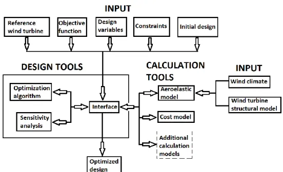
Fuglsang et al. (Peter Fuglsang et al., 2002) present a numerical optimization algorithm
that is coupled with an aeroelastic and cost model, allowing the optimization of stand-alone flat
terrain and offshore wind farm wind turbines for different operations and wind conditions (refer
to Error! Reference source not found.). The work is used to identify the potentials in site
specific design for offshore wind turbine farms by means of site specific design optimization of
a reference 1.5 MW stall regulated wind turbine considering the hub height, rotor speed, rotor
diameter and rated power as the design variables.
In 2010, Bottasso et al. (Bottasso, Campagnolo, & Croce, 2010) exercised a thorough
description of a multi-disciplinary design optimization procedure. The optimization is realized
through the maximizing of a merit function under constraints respecting relevant design
requirements (Commission, 2005, 2006). Bottasso et al. (Bottasso et al., 2010) assumed that
the weight is correlated to the cost but does not use a particular cost model, arguing that a
reliable cost model is not offered to the public. The multi objective design is not formulated as
a Pareto optimal problem, but rather as a combined cost defined as the ratio of the annual
energy production to the total weight. The optimization task is a nested constrained optimization
problem that has among its constraints a second set of constraints. Since the direct solution of
2010) applied a sequential constrained optimization where the procedure is divided into two
stages. In the first stage, the maximum AEP for minimum blade weight is calculated.
Figure 5 : Design tool of Fuglsang et al. (Peter Fuglsang et al., 2002) (reproduced from (Peter Fuglsang et al., 2002)).
Kusiak et al. (Kusiak, Zhang, & Li, 2010) introduced a data-driven approach to study the
impact of turbine control on their vibrations and power output. The authors developed model
for prediction of vibrations and the produced power using neural networks. To illustrate the
importance of the three objectives (two vibrations and the power output), a weighted sum of
these objectives is minimized:
𝑚𝑖𝑛 (𝑤1𝑦1(𝑡) + 𝑤2𝑦2(𝑡) + 𝑤3
1 𝑦3(𝑡)
) [1.6]
where y1(t) is the estimated vibration of the drive train; y2(t) tower vibration model; y3(t)
estimated power output model.
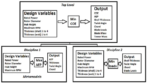
Maki et al. (Maki, Sbragio, & Vlahopoulos, 2012) conducted a new multi-level system
Figure 6 : Flowchart of the optimization scheme of Maki et al. (Maki et al., 2012) (reproduced from (Maki et al., 2012)).
The cost of energy is the overall system level objective, arguing that the work that
optimize the ratio of lift to drag do not reflect the least cost of energy. Maki et al. inspired their
work from other areas in engineering that seek one overall global optimum design such as in
naval architecture (Cox et al., 2001; Moraes, Vasconcellos, & Almeida, 2007), automotive
engineering (H. M. Kim, Michelena, Papalambros, & Jiang, 2003; Sinha, 2007), mechanical
engineering (I. Y. Kim & de Weck, 2005; Venkayya, 1989), in biomedical engineering (Moles,
Mendes, & Banga, 2003) and others (Jouhaud, Sagaut, Montagnac, & Laurenceau, 2007;
Lewis, 2001). The design variables (rotor diameter, rotational speed, maximum rated power,
hub height, structural characteristic of the blade, geometric characteristic of the blade) are
separated into blade parameters and rotor parameters to find the minimum cost of energy of
the entire system. The system design analysis was developed using the NREL tools (NREL)
with a cost and scaling model from the work of Fingersh et al. (Fingersh, Hand, & Laxson,
2006). The two technical design disciplines that compose the design optimization of the wind
turbine are:
2. Structural design of the blade for minimum bending moment at the root
In a compelling study conducted by Ning et al. (A. Ning, Damiani, & Moriarty, 2013), the
authors study the impact of various objective functions on the quality of the optimal solutions.
Three different optimization objective functions were examined:
1. Maximization of the Annual Energy Production (AEP)
2. Minimization of the turbine mass to AEP ratio
3. Minimization of the cost of energy (CoE)
Ning et al. (A. Ning et al., 2013) assumed that the weight loads are added to the aerodynamic loads at 0 degree pitch and the 3 o’clock azimuthal position, which is considered the worth case for edgewise loads. The 2D airfoil correction take account the rotational effects
in the solver using a Du-Selig (Du & Selig, 1998) for lift and Eggers(Eggers, Chaney, &
Digumarthi, 2003) for drag. The method proposed by Viterna (Viterna & Janetzke, 1982) was
used for the extrapolation of the results for the -180º to +180º range. The NREL 5MW geometry
was used as a reference (Jason Mark Jonkman, Butterfield, Musial, & Scott, 2009) with a
preliminary evaluation by NUMAD for the initial layup (Resor, 2013) and the materials were
derived from the database carried by Mandell (Mandell & Samborsky, 1997). A
parameterization of the chord, twist and spar cap distribution along the blade length was
completed to ensure the efficiency and flexibility in describing the geometry. The cost model
used in (A. Ning et al., 2013) was proposed by Fingersh (Fingersh et al., 2006) but some
modifications were implemented in the optimization tool. One of the main adjustments was the
computation of the blade mass using structural models and not scaling laws. Another
modification is that the blade cost was supposed to be a linear function of the blade mass and
1. deprived of a blade mass computation
2. with mass constraints by the use of surrogates
When maximizing the AEP using the first method, the optimization strategy lead to the
design of multiple blades with the same AEP for different blade masses; meaning the existence
of weak local optimum solutions.
The blade mass constraints were imposed in diverse forms. One possibility of
constraining the blade mass is limiting the root bending moment. However, the root bending
moment constraint does not alter the solution since the primary objective is to maximize the
AEP, which tends to decrease the root bending moment. Another surrogate is inspired from
aircraft design, using wing weight portion scaling, where the weight of the wing is divided into
a portion that scales with the planform area and another that scales the required loading (S. A.
Ning & Kroo, 2010). In this strategy, the optimal solution is realized by decreasing the root
chord in exchange for a larger chord at maximum chord location. The aerodynamic
performance of the blade is improved but structurally worth, therefore a restriction on the stress
at the blade root is set. This surrogate alters the optimization problem; applying a sequential
algorithm where the maximization of the AEP is followed by the minimization of the blade mass.
An alternative approach is forcing the structural analysis to dictate the blade shape whereas
the aerodynamic analysis only dictates the airfoil shape; this is known as blade shape and
airfoil decoupling. This approach changes the optimization because the structural analysis
must be repeated one final time to guarantee that the constraints are satisfied. The results of
each surrogate were compared with the minimum cost of energy formulation and a maximum
energy reduction of 0.35% was recorded from the blade & airfoil decoupling and a 0.3%
reduction in portion scaling. Although both approaches lead to decreases in cost of energy,
they are still inferior to metrics that combine the aerodynamic and structural performance.
Ning et al. (A. Ning et al., 2013) deduced that maximizing AEP and then minimizing the
choice is to minimize the ratio of the turbine mass to the annual energy production. Results
showed that even if a proper nacelle and tower model are not used, a constant estimate of their
mass must be included; otherwise potential decreases in rotor mass are overemphasized,
which can lead to exaggerated aerodynamic performance. If a fixed tower mass is chosen,
then the optimization showed good results at a fixed rotor diameter, but for a variable-diameter
design, inaccurate diameters were predicted. On the other hand, when the tower is allowed to
resize, caution must be taken because the tower mass consists a large portion of total mass,
but tower cost is a rather small to the total cost. Thus, minimizing the m/AEP ratio may risk
overemphasizing the role of the tower if careful care in the construction of the problem is not
pursued. Equivalently, the objective function may over incentivize the solver to decrease the
tower mass at the expense of aerodynamic performance
1.4 SUMMARY
Within the last 15 years, wind turbine technology has reached maturity. The growing
world-wide market will culminate to further improvements. The advances in horizontal wind
turbine performance strategies and techniques will result to further cost reductions and in the
near future wind energy will be able to compete with fossil fuel. It can be anticipated that the
number of research publications that use optimization techniques to solve for the optimal
horizontal wind turbine blade, airfoil shape and rotor design problems have increased
significantly in recent years.
The parameters that designers seek to optimize under a set of design constraints have
evolved in recent years. Wind turbines are designed using an integrated design process where
several important parameters are included such as annual energy production, extreme and
fatigue loads, as well as a turbine component cost model. Ultimately, the objective is to
Lately, we have witnessed an increased awareness of improving the wind turbine
performance. Practical constraints associated with physically harnessing the kinetic energy in
wind to generate electricity relate to the suitability of:
1. Wind speeds
2. Land, access and ecological issues
3. Residential annoyance and shadow flicker
4. Structural and mechanical limitations
All of the above setbacks will interfere the wind farm project if not carefully taken into
consideration during a preliminary design phase. Therefore, in order to build an efficient and
reliable wind turbine blade design tool, the various optimization strategies and design
CHAPTER 2
MATHEMATICAL MODELS OF THE WIND TURBINE OPTIMIZATION PROBLEMS
2.1 INTRODUCTION
In the previous chapter, we presented the most relevant studies conducted in the field
of wind turbine optimization. In order to present an efficient and reliable wind turbine blade
design tool, a thorough examination of the mathematical models must be conducted.
Accordingly, in this chapter, we will inspect the structure of the mathematical models used in
WTOP. At the outmost, the objective functions are assessed followed by a taxonomy of the
wind turbine design constraints.
2.2 OBJECTIVE FUNCTIONS
The parameters that designers seek to optimize have evolved in recent years. In the
early days, designers focused on the maximization of the power coefficient CP (the fraction of
power in the wind that can be extracted by the wind turbine). This optimization strategy had a
direct impact on the blade shape, resulting in larger root chords, larger taper and very high
blade twist. With the increase of the rotor size for higher power production, the problems
occurring in transportation and production began to interfere with the design. As the
maximization of the power coefficient occurs at a particular tip speed ratio on fixed speed stall
regulated turbines, the tendency shifted towards a second optimization parameter - the
maximization of energy production. The maximization of the energy production is achieved over
a given period of time (e.g. one year) and wind speed spectrum rather than a particular wind
speed. Increased knowledge about the influence of rotational effects in stall brought a new
are translated into costs by introducing a cost model and by slightly reducing the power
coefficient, loads on the wind turbine can be largely reduced. This type of optimization resulted
in slender blades, with lower solidity. The design of a wind turbine rotor is complex, since design
variables are dynamic, and some have conflicting behaviors within the definition of the CoE.
For example, the rotor diameter is increased for a higher energy capture but this result into
higher loads that increase the cost of energy.
In (Ashuri, Zaaijer, van Bussel, & van Kuik, 2010; Bak, 2013; Benini & Toffolo, 2002; Eke
& Onyewudiala, 2010; P Fuglsang & Aagaard Madsen, 1994; Peter Fuglsang & Aagaard
Madsen, 1995; Peter Fuglsang et al., 2002; P. Fuglsang & Madsen, 1999; Giguere & Selig,
2000; M. Grujicic et al., 2010; Maki et al., 2012; A. Ning et al., 2013; W. Xudong et al., 2009),
the authors argue that the main objective in wind turbines is towards the minimization of the
cost of energy rather than the maximization of the aerodynamic performance of the wind blade
in order to make wind energy competitive with other energy sources. One of the earliest
approaches was to restrain the blade weight growth with the increase of its length by limiting
the chord length and increasing instead the lift coefficients of wind turbine airfoils. This strategy
is inspired by the fact that the blade is one of the most important components of wind turbines
and its structure has significant impact on the stability and the cost of the wind turbine. Hence
to lower the cost, the weight should decrease but in order ensure the stability, the weight has
to be increased. So, designing a blade with minimal blade mass requires the right balance
between the mass and the stability. Wind turbines dimensions are becoming larger and it can
be assumed that gravity and inertia loads become as significant as aerodynamic loads, hence
the importance of weight reduction. However, common alternatives for the choice of the
objective function are the maximization of the annual energy production or the power
coefficient, blade mass minimization and maximization of the rotor thrust and torque.
In this chapter, the objective functions that were explored are divided in four main
categories: minimization of cost of energy, maximization of the power production, minimization