Cover page
Title: Parametrical study on the behaviour of steel and composite cellular beams under fire conditions
Authors: O. Vassart (ArcelorMittal R&D, G.-D. of Luxemburg)
C. G. Bailey (University of Manchester, UK)
G. Bihina (CTICM, France)
M. Hawes (ASDWestok Limited, UK) A. Nadjai (University of Ulster, UK) C. Peigneux (University of Liège, Belgium) W. I. Simms (SCI, UK)
ABSTRACT
This paper describes an extensive parametric study on the behaviour of cellular beam under fire conditions.
Different finite element models using shell elements were developed considering both material and geometrical non-linearity; CAST3M [1], ANSYS [2] and another one in SAFIR [3]. They were calibrated on the basis of a new experimental test campaign performed in the scope of the project FICEB+ [4] funded by the Research Fund for Coal and Steel
The comparison between the finite element prediction and actual experimental results showed a good agreement in terms of failure modes, load deflection relationship and ultimate loads. At failure, temperature measured during the fire tests indicated that failure arising by web post buckling of cellular beams in fire cannot be simply estimated by applying temperature dependent reduction factors on strength alone, as given in codes.
A design model representing the behaviour of cellular beam in fire conditions has been developed by Vassart [5-7]. This design model is able to predict the complex behaviour of cellular beam in case of fire comprising web-post buckling and Vierendeel bending, as well as standard flexural bending.
The results of the Finite Element Models are compared in terms of critical temperatures and failure mode obtained using the design model.
This paper also contains some tests results that were used to calibrate the FEM model and the comparison between analytical and FEM models.
EXPERIMENTAL TEST CAMPAIGN Beam geometric and material properties
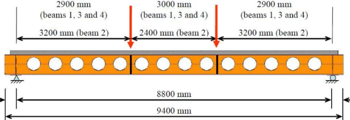
An overall view of the four beams is shown in Fig. 1. As part of the composite floor plate, beams 1, 3 and 4 were considered to be secondary beams, and beam 2 was considered as a primary beam. They were fire designed according to [8].
The main geometric and material properties of the beams are shown in Table 1. In addition to the web stiffeners at load points and at its end supports, for beam 4, there was a one side stiffener at each web-post. The upper steel flange was fully connected to the 120mm deep composite slab, which comprised a COFRASTRA 40 ® re-entrant deck, via Nelson headed studs.
The slab width was 2.20 m which equals to the effective width beff according to Eurocode 4 part 1.1.
[9], i.e. 2× L/8. As for the reinforcement steel, a mesh of 252 mm²/m was used.
Table 1 : Geometries and properties of the tested beams
Failure mode
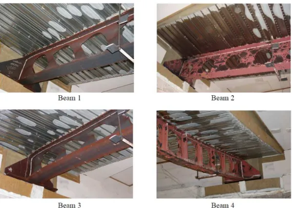
For both beam 1 and beam 3, the failure was due to web-post buckling near the beam supports (Figure 2), which is one of the usual modes of failure observed for such beams in fire situation.. Besides, because of its web-post stiffeners, beam 4 could only have a flexural bending failure, as it behaved like an “ordinary” beam. Hence, as beam 1 and beam 4 had the same cross-section, and as their deflection vs. time graphs are very close, beam 1’s collapse might have been caused by combined web-post buckling and flexural bending.
As for the primary beam, i.e. beam 2, no web-post buckling was observed, which leads to the conclusion that this beam also failed by flexural bending.
Fig. 2: Deformed beams
NUMERICAL MODELING
The parametric study was run conducted using SAFIR (version 2007a), CAST 3M and Ansys.
SAFIR Mechanical model
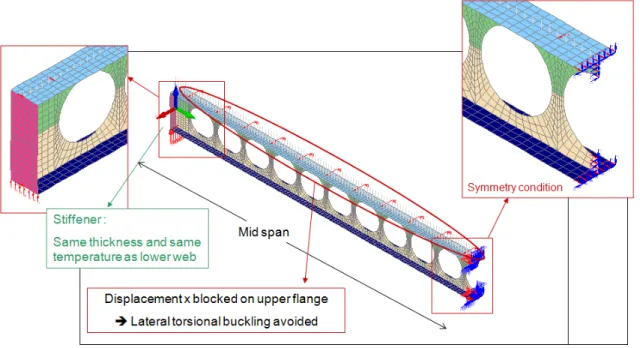
For the mechanical model of the steel profile, 4-node shell finite elements were used, as shown in Figure 3.
The beam was simply supported. Symmetry was used at the mid-span and the lateral displacement of the upper flange was restrained to avoid any lateral torsional buckling (Figure 3).
Fig. 3– Boundary conditions for modelled beam
An initial deformation was given to the beam (Figure 4a). This deformation results from the product of a sine curve on the height of the profile (Figure 4b) and of a cosine curve on the length of the beam. The maximum amplitude was 2 mm.
Fig. 4: a) CB with amplified initial deformation (x 15) and b) initial deformation of the web-post
The assumed material properties of the steel were taken according to Eurocode EN1993-1-2 [10], with the variation of different parameters with temperature taken from Eurocode EN1993-1-2.
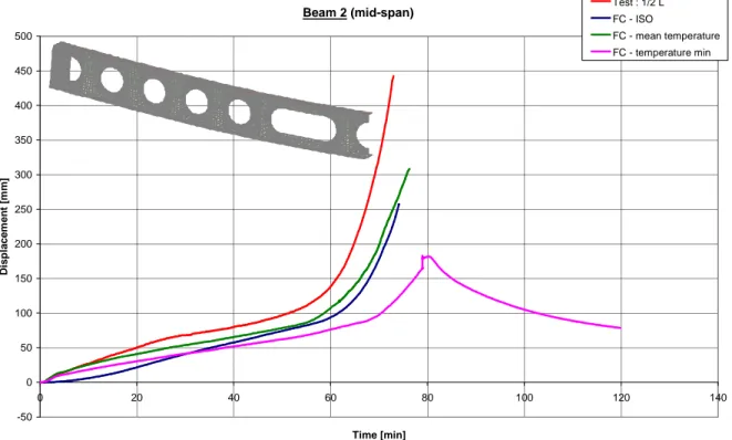
The Figure 5 shows the comparison between FEM model and the fire test beam 2. Beam 2 (mid-span) -50 0 50 100 150 200 250 300 350 400 450 500 0 20 40 60 80 100 120 140 Time [min] D is p la c e m e n t [m m ] Test : 1/2 L FC - ISO FC - mean temperature FC - temperature min
Fig. 5: Time–Displacement diagram of the beam 2 at mid-span
Ansys Numerical Model
The Ansys model was based on a 3D mesh made of shell and beam elements (Figure 6a). As the ribs were neglected in the model, only the concrete part above the steel deck was modelled (Figure 6b). The experimental measured yield strengths were used.
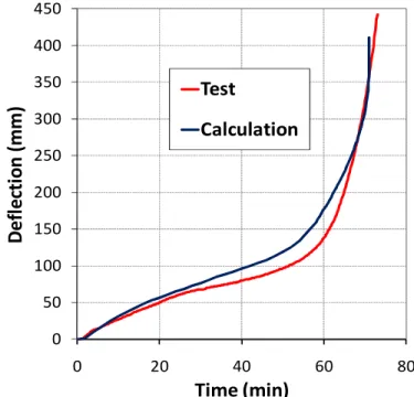
Due to mid-span symmetry, axial restraints and rotational restraints about the two axes of mid-span cross-section were applied. Support conditions were modelled by restraining vertical displacements. Also, so as to prevent lateral torsional buckling, flange-web junctions in both tees were laterally restrained. The mechanical load was applied to the top steel flange, including self-weight. The analysis was run until numerical failure. Figure 7 shows the comparison between the FEM model and the fire test beam 2.
0 50 100 150 200 250 300 350 400 450 0 20 40 60 80
D
e
fl
e
ct
io
n
(
m
m
)
Time (min) Test CalculationFig. 7: Time-Displacement diagram of the beam 2 at mid-span
Conclusion on FEM Modelling
A good agreement between the tests and both FEM models is observed, in terms of failure modes and critical temperatures. Thus, theses models can accurately predict the mechanical behaviour of a simply-supported composite cellular beam at elevated temperatures, and can be used for the parametric study which aims to check the relevance of the simplified design method.
PARAMETRICAL STUDY
This parametrical study was made varying the following parameters:
• steel profile
• geometry of the web-post
• steel strength limit
• loading type
• slab type
P a ra m e te r m in im u m v a lu e m a x im u m v a lu e s te p P S (P u re s te e l) C B (C o m p o s it e B e a m ) sp a n L 8 m 2 0 m 4 m 4 4 P u re S te e l b e a m o r C o m p o si te B e a m P S - C B 1 1 fir e c u rv e 1 1 lo a d in g G Q 2 1 st e e l p ro fil e IP E … H E … 3 3 st e e l g ra d e o f th e p ro fil e fy 2 2 to ta l h e ig h t o f th e p ro fil e Ht 1 1 h e ig h t lo w e r p ro fil e HL P 1 1 u p p e r fla n g e t h ic kn e ss tUF 1 1 u p p e r w e b t h ic kn e ss tUW 1 1 lo w e r w e b t h ic kn e ss tLW 1 1 lo w e r fla n g e t h ic kn e ss tLF 1 1 d ia m e te r o f o p e n in g s a0 a0 " n o rm a l" a0 m a x -2 2 p o si tio n o f th e f ir st o p e n in g w0 -1 1 w e b p o st w id th w -2 2 p ro te ct io n n o p ro te ct io n 1 1 co n cr e te s la b t h ic kn e ss hc o ve ra ll d e p th o f th e p ro fil e d s te e l s h e e tin g hp co n cr e te e ff e ct iv e w id th beff -1 co n cr e te g ra d e fck 1 co n cr e te s la b r e in fo rc e m e n t As 1 re in fo rc e m e n t g ra d e fsk 1 d e g re e o f sh e a r co n n e ct io n h -1 1 9 2 1 9 2 = t o ta l n u m b e r o f si m u la tio n s fo r st e e l C B = t o ta l n u m b e r o f si m u la tio n s fo r co m p o si te C B d e p e n d in g o f th e s te e l p ro fil e n u m b e r o f d if fe re n t b e a m s IS O f ir e c u rv e 2 fo r a0 " n o rm a l" : wm a x a n d wm in ( > 5 0 ) fo r a0 m a x : w"o p tim u m " a n d w"s m a ll v a lu e " m in ( 2 m ; L /4 ) c o n c re te s la b P S : I P E 3 0 0 H E A 4 0 0 H E M 9 0 0 C B : I P E 3 0 0 H E A 4 0 0 I P E 3 0 0 /H E A 4 0 0 IP E 3 0 0 : S 2 7 5 S 3 5 5 H E A 4 0 0 e t H E M 9 0 0 : S 3 5 5 S 4 6 0 IP E 3 0 0 /H E A 4 0 0 : 3 5 5 /3 5 5 3 5 5 /4 6 0 d e p e n d in g o f th e s te e l p ro fil e , a0 a n d w d e p e n d in g o f th e s te e l p ro fil e d e p e n d in g o f th e s te e l p ro fil e d e p e n d in g o f th e s te e l p ro fil e d e p e n d in g o f th e s te e l p ro fil e 1 0 0 % g e n e ra l p ro p e rt ie s C 2 5 /3 0 if S 2 7 5 a n d S 3 5 5 C 3 0 /3 7 if S 4 6 0 S 5 0 0 0 .0 0 % h p = 5 9 m m h c = 6 1 m m h p = 0 m m h c = 1 2 0 m m 6 0 s te e l p ro fi le P S : 2 c o n ce n tr a te d lo a d s - d is tr ib u te d lo a d ( lo a d r a tio = 0 .5 ) C B : d is tr ib u te d lo a d ( lo a d r a tio = 0 .5 ) h p h c b e ff
Sum-total, 192 simulations are foreseen for pure steel beams and 192 simulations for composite beams.
Results of the parametrical study
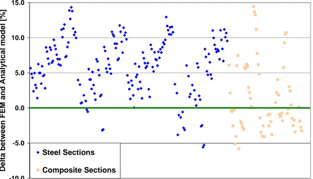
The critical temperature and the failure modes were assessed using finite element models and compared with analytical model using the following formula:
(
−)
× =∆
100 _ _ _ FEM Analytical FEM Temp Crit Temp Crit Temp CritThis means that when the points are positive, the analytical model predicts a lower critical temperature than the finite element model and so is considered conservative (i.e safe sided).
Figure 8 shows the comparison of the results between FEM and analytical model.
-10.0 -5.0 0.0 5.0 10.0 15.0 D e lt a b e tw e e n F E M a n d A n a ly ti c a l m o d e l [% ] Steel Sections Composite Sections
Fig. 8: Time-Analytical model Vs FEM Modelling
Analysing Figure 8, it can be pointed out that the analytical models can predict the critical temperature of steel cellular beams. The analytical model, based on Eurocodes principles, provides safe sided results with acceptable level of accuracy.
It can also be pointed out that the analytical models can also predict the critical temperature of composite cellular beams.
Some numerical simulations still running and points of comparison with analytical models will be added for composite sections. Moreover, the numerical modelling are still analysed because some discrepancies in the results appeared between the different finite elements models for composite sections.
CONCLUSIONS
The different FEM models were able to reproduce with an acceptable level of accuracy the complex behaviour of cellular beams in fire conditions.
On the basis of theses different FEM models, a parametric study was made to validate the developed analytical model.
The analytical model was again validated by this parametrical study and can be used for the prediction of the critical temperature of cellular beam in case of fire. This model takes into account the complex behaviour of cellular beams in fire conditions and is based on the Eurocodes principles taking into account the loss of material properties and stiffness required in the Eurocodes. This model was implemented in a design software called ACB+ and can be downloaded for free on
www.arcelormittal.com/sections .
REFERENCES
1. CAST 3M - GUIDE D'UTILISATION : CEA/DMT/LAMS
2. Ansys, Inc. (2006). “ANSYS Academic version, Release 10.0, Help System”.
3. SAFIR. A Thermal/Structural Program Modelling Structures under Fire, Franssen J.-M., Engineering Journal,
A.I.S.C., Vol 42, No. 3 (2005), 143-158
4. Technical annex of RFCS project FICEB+ (FIre resistance of long span Cellular Beam made of hot rolled
profiles), ArcelorMittal, WESTOK, SCI, CTICM, ULG, Ulster University, 2006
5. Nadjai A, Vassart O., Ali F., Talamona D., Allam A., Hawes M. “Performance of Cellular composite floor
beams at elevated temperatures” Fire Safety Journal, Volume 42, Issues 6-7, September-October 2007, Pages 489-497
6. Vassart O. , Bouchaïr A., Muzeau J-P and Nadjai A.“Analytical model for the web post buckling in cellular
beams under fire” Fifth International workshop Structures in Fire, Singapore 2008
7. Vassart O. .“Analytical model for cellular beams made of hot Rolled sections in case of fire” PhD thesis
Université Blaise Pascal, Clermont Ferrand, 2009
8. ASDWestok Cell Beam Software, V 3.01, Steel Construction Institute
9. CEN, Eurocode 4 - Design of composite steel and concrete structures – Part 1-1: General rules and rules for
buildings, 2005