HAL Id: hal-00861320
https://hal.archives-ouvertes.fr/hal-00861320
Submitted on 19 Sep 2018
HAL is a multi-disciplinary open access
archive for the deposit and dissemination of
sci-entific research documents, whether they are
pub-lished or not. The documents may come from
teaching and research institutions in France or
abroad, or from public or private research centers.
L’archive ouverte pluridisciplinaire HAL, est
destinée au dépôt et à la diffusion de documents
scientifiques de niveau recherche, publiés ou non,
émanant des établissements d’enseignement et de
recherche français ou étrangers, des laboratoires
publics ou privés.
A phenomenological model of the third body particles
circulation in a high temperature contact
Pauline Lepesant, Christine Boher, Yves Berthier, Farhad Rezai-Aria
To cite this version:
Pauline Lepesant, Christine Boher, Yves Berthier, Farhad Rezai-Aria. A phenomenological model of
the third body particles circulation in a high temperature contact. Wear, Elsevier, 2013, 298-299,
pp.66-79. �10.1016/j.wear.2012.08.019�. �hal-00861320�
A phenomenological model of the third body particles circulation in a high
temperature contact
P. Lepesant
a, C. Boher
a,n, Y. Berthier
b, F. Re´zai-Aria
aaUniversite´ de Toulouse, Mines Albi, ICA (Institut Cle´ment Ader), Campus Jarlard, F-81013 Albi cedex 09, France bUniversite´ de Lyon, CNRS, INSA-Lyon, LaMCoS UMR5259, F-69621 Villeurbanne, France
Keywords: High temperature Third body Wear model Surface topography
a b s t r a c t
In high temperature forming processes (forging, rolling, die-castingy) the tool surfaces are the privileged places for mechanical, thermal and physico-chemical solicitations. More precisely, friction and wear play an important part in tool surface damage. The tool steel grades exhibit damages such as local plastic deformation, plastic flow, carbides fragmentation and oxidation. Oxide scales, which depend on the contact temperature, influence wear mechanisms and have to be considered in the wear model development.
The aim of this work is to assess the third body particles circulation in a high temperature friction contact.
The wear investigations are carried out using a high-temperature pin-on-disc tribometer. The pin is made of X38CrMoV5 steel (AISI H11) and the disc is made of common steel (C38, AISI 1035). The setting temperature is 900 1C. All experiments are performed under constant load and velocity. The special design of the pin surface contributes to the trapping of third body particles and to the identification of the third body flows.
Environmental Scanning Electron Microscopy (ESEM, in ambient air) observations and Energy Dispersive Spectrometry (EDS) investigations have revealed that different types of third body particles circulate in the contact. Based on these observations and chemical analyses, a phenomenological model of the third body particles circulation in a high temperature contact is proposed, based on the third body concept approach.
1. Introduction
A specific disadvantage of the hot and warm forming processes is that the tools are exposed to high cyclic thermal and mechan-ical stresses. These stresses cause failure of the tools because of wear and thermo-mechanical fatigue[1]. Barrau[2,3] and Boher[4] studied the friction and wear behaviour of hot work tool steel for forging. These studies showed that wear of X38CrMoV5 (AISI H11) was controlled by plastic deformation. It is considered that the third body particles are formed and the wear-loss occurs when the accumulated plastic deformation at sub-surface exceeds ‘‘a critical strain’’ or ‘‘rupture limit’’. According to these studies, a physical model based on cumulative cyclic plastic straining has also been addressed. Moreover, these works showed that the near-surface layers are exposed to a high plastic deformation, which modifies texture and leads to the formation of Tribologically Transformed
Structures (TTS)[5]. In addition, previous studies have also been addressed on the oxidation and wear mechanisms of highly alloy steels and white cast iron under high temperature friction[6–8]. More specifically, the contact and superficial damages between the pieces and the tools not only depend on the tribological conditions but also on the nature and mechanical properties of oxides in the contact. Thus, a hard oxide may result in abrasive behaviour whereas a ductile oxide may decrease the friction coefficient as well as the wear. The second factor often considered is the thickness of the oxide scale which is associated with its adherence to the matrix. Commonly, the friction coefficient decreases in presence of oxides and it seems established that the friction coefficient increases when the scale thickness decreases.
High temperature friction implies different aspects related to the oxidation of the surfaces, the oxide scale deformation and the particles circulation which is related to third body flows. These different topics will be addressed in the first part of this paper.
Oxidation has to be studied when high temperature is of concern. However, the oxidation that takes place within a tribological test cannot be related to a static oxidation test. Indeed, Blau et al. [9] showed that oxidation under stresses
n
Corresponding author. Tel.: þ33 5 63493169; fax: þ33 5 63493242. E-mail addresses:[email protected],
cannot be compared to static oxidation. Species which form on mechanically damaged surfaces present a different composition from those formed without a mechanical loading. Another study [10]also has addressed other factors which can affect the metallic surfaces response at high temperature. These are the mechanical properties of the reaction products on the surface; the capability of the surfaces to form stabilized glaze layers; the strain and rupture strength of the bulk materials and the glaze layers. This last factor has been studied by Wang et al.[11]. The results of the frictional tests made for this study showed that the matrix strength has to be considered to know whether the oxides from the glaze layers are protective, or not, against wear. If the matrix is strong enough, the oxides formed during friction have a positive influence on wear. On the contrary, if the matrix is not strong enough, the oxides from the glaze layer do not protect the surfaces from wear and they may even act as an abrasive third body. Other authors study the effect of the glaze layers[12–15]. Indeed, Inman et al. defined wear maps for nickel-, cobalt-, and iron-based alloys. These maps have been built according to the behaviour of the sliding materials under different sliding velocities and temperatures. According to these parameters, different types of wear occur (severe and mild) and are linked with the presence, or not, of a glaze layer. Actually, there is always a border between severe wear and mild wear whatever the conditions, and this border is influenced by the glaze layer. Inman et al. also characterised this glaze layer [16]. They showed that it is composed of nano-structured grains. Indeed, a process called ‘‘fragmentation’’ involving deformation, generation of dislocations, formation of sub-grains and their increasing refinement causing increasing misorientation, was responsible for the formation of these nano-structured grains.
Another effect of implied stresses on oxidised surfaces is the deformation of the oxides. Indeed, the tribological stresses could be important enough to cause the deformation and the plasticity of the oxides. The plastic deformation of the oxides is not the same as the plastic deformation of polycrystalline solids [17]. These last ones can be plastically deformed via the dislocations motion which needs at least five independent slip systems[18]. In the case of oxides, this dislocations motion is not the same because of the smaller number of independent slip systems. This explains the different mechanisms which take place in the plastic deformation of oxides. In addition, oxides must be considered as a ‘‘living material’’, since the oxide layer changes during oxidation. Indeed, oxidation implies a continuous evolution of the oxide layer thickness and the oxide layer may present a gradient of physical and mechanical properties due to the element diffusion. Sch ¨utze[19]introduced another phenomenon which can occur during a high temperature contact that is called ‘‘pseudoplasticity of the oxides’’. It is defined as the combination of oxide cracking
and crack healing (‘‘self-healing’’). At low strain rates the rate at which the oxide crack faces move apart is lower than the oxide growth rate within the oxide crack. Thus, the oxidation process closes the crack more or less instantly. Indeed, at high temperature, pseudoplasticity can take place and in this case, no fracture of the oxide layer is observed. This lack of observed cracks can lead to the thought that the layer has not sustained a deformation important enough to cause its rupture. But pseudoplasticity could explain a large deformation of oxides without cracks because the created cracks are actually healed.
Another scientific approach useful for our study concerns the circulation mechanisms for the particles inside a contact. More particularly, Jiang et al. [20,21] performed high temperature friction tests with a nickel-based alloy and defined circulation mechanisms such as rotation, skidding and rolling. This last one depends on the adhesion of the adjacent particles. Based on these mechanisms, the authors developed a mathematical model to quantify the wear volume, based on the probability to produce a size-defined particle. This model also considers the surface cover-age of the wear surfaces by two distinct layers: A compacted particle layer and a glaze layer. The authors improve continuously this model especially while taking into consideration the effect of oxygen [22]. Another approach of the particles circulation is based on the concept of the third body[23]. The objective of this other approach is also to understand the first steps of the particles formation and to define the particles circulation as particles flows. The aim of this paper is to give a better insight into the formation of the particles and their circulation in the contact. To achieve this goal, we use the third body concept.
This concept has been set up for friction studies in order to understand the evolution of the friction contact during sliding and particularly the implication of the third body particles on friction. The third body is defined as the material between the two first bodies. It results from the wear of these two first bodies and separates them in order to avoid their further degradation.
In the third body concept, five sites and four modes of accom-modation of the friction contact exist in order to accommodate the speed difference between the two first bodies[24,25]. These sites and modes are shown inFig. 1. The sites S1and S5are the two first bodies,
S2and S4the screens and S3the third body. The screens, or surface
complexes, are defined as the interfaces which separate the first bodies from the third body. They generally have a different chemical composition from the first bodies but belong to their surfaces, in opposition to the third body. Concerning the modes, M1represent the
elastic deformation, M2 the failure, M3 the shearing and M4 the
rolling. The combination of one mode with one site gives an accommodation mechanism. Several mechanisms can coexist in the contact and evolve with time.
S1 S2 S3 S4 S5 MODES Mj M1 M2 M3 M4 SITES Si SCREEN THIRD BODY S0 M HA C E N I L A C SY ST M E FIRST BODY S1 S5 S3 S0 S0 S1 S2 S3 S4 S5 ACCOMMODATION MECHANISM Site.Mode SiMj MODES Mj M1 M2 M3 M4 SITES Si SCREEN THIRD BODY S0 M HA C E N I L A C SY ST M E FIRST BODY S1 S1 S5 S5 S3 S3 S0 S0 S0 S0
To explain the circulation of third body particles, third body flows (Q) are defined within the contact (Fig. 2,[26]) and these flows contribute to protect or not the contact surfaces. The source flow Qsis divided into two parts: The external one, with artificial
third body inserted in the contact, and the internal one which is constituted of the natural third body particles detached from the contact surfaces. Between the two first bodies is the internal flow Qiwhich leads to the external flow Qe. This last one can be divided
into two flows: The wear one Qw made of particles definitely
ejected from the contact and the recirculation one Qrconstituted
of particles which can be reintroduced in the contact. These reintroduced particles can recirculate in different ways: Moving inside the contact, being comminuted, being trapped or being readhered to one surface or the other. Finally, there is a plastic flow Qp present in the first bodies which can lead to the
detachment of third body particles.
The use of these previous notions will be important for the identification of the production of third body particles, their nature and how they circulate in a high temperature contact. The aim of this paper is to introduce a phenomenological model of circulation of third body particles occurring in the first instants of friction. Another objective is to define the third body particles circulation as a function of accommodation mechanisms and of the different flows activated in the contact. The tribological experiments are performed with a pin-on-disc tribometer at 900 1C. This configuration facilitates the understanding of the mechanisms taking place in a high temperature contact and the test conditions are easier to control than a hot forming tool. The pin is made of X38CrMoV5 steel (AISI H11) which is a well-known material while the disc is made of C38 steel (AISI 1035). We will use a special pin surface design for trapping and studying the circulation of the third body.
2. Experimental equipment, materials and procedure 2.1. High-temperature pin-on-disc tribometer
The high-temperature pin-on-disc tribometer developed in our laboratory is reported in [8]. The pin presents a plane contact surface with a diameter of 2 mm. The disc is a cylinder with a diameter of 30 mm. It can be heated up to 1000 1C by a frequency induction heating system. The surface temperature of the disc is controlled during the whole test by a IR-bichromatic pyrometer. The disc is first heated up to 900 1C. Once the disc surface temperature is reached, the disc is pre-oxidised during 10 min while the pin is out of the contact at room temperature. When the disc surface temperature is stabilised, the pin is put on the disc surface and the friction test starts immediately. The pin is then heated up by conduction and radiation. The tangential forces are continuously measured using a strain gauge and the friction
coefficient is recorded with a software developed on LABVIEW, as well as the pyrometer temperature.
2.2. Circulation of third body particles
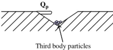
In order to investigate the third body particles circulation in the contact, we decided to make indentations on the pin surface to create particle traps and facilitate the observation of the first body plastic flow as indicated inFig. 3.
These indentations are made using a Vickers indenter (HV30). The pin surfaces are then polished to eliminate the plastic ploughing around the indentations so as to avoid their interaction with the natural material flow induced by friction. Several indentations are made on the whole surface, from the entry to the exit of the pin, in order to obtain the maximum of information and follow the circulation of third body particles. When the indented surface is polished, the depth of the indentations decreases but their dimensions are well known with the topo-graphical measurements. Even if the indentations could disturb the contact, we consider that the disturbance is minor compared to the amount of information that they can provide.
To get information about the third body particles circulation and the wear behaviour, we perform Environmental Scanning Electron Microscopy (ESEM) observations (in ambient air) and topographical exams of the contact surfaces. The ESEM observa-tions are made on the surface of the wear scars and on cross-sectioned pins. To perform these cross-cross-sectioned observations, the pin surface is nickel plated post-mortem before polishing for
FIRST BODY FIRST BODY
FIRST BODY
Plastic flow Qp FIRST BODY
Fig. 2. Tribological circuit for an elementary two-dimensional contact[26].
Qp
Third body particles
Fig. 3. Schematic representation of the plastic flow observed inside the indentations.
Table 1
Friction test conditions. Normal load 40
Sliding speed 300 rpm or 0.4 m/s(linear) Test duration 120
Disc temperature 900
cross-section observations. The nickel plating process permits to keep the third body particles still at their place during polishing but it can hide some small particles. Both modes of observations are used: Secondary electrons (SE) for the topographical contrast and back-scattered electrons (BSE) to reveal the chemical com-position differences. These observations are coupled to Electron Dispersive Spectroscopy (EDS) analysis in order to have a first identification of the chemical composition of the observed particles. Topographies of the surface of pins and discs are carried out with a confocal microscope ALTISURFswith extended z-axis field
using Halogen as a light source. We use an optical sensor of 350
m
m measuring range with a 11 nm axial resolution for the pins, and an optical sensor of 3 mm measuring range with a 90 nm axial resolution for the discs. The scanning advance step (x, y) is 1m
m for the pins and (5, 10)m
m for the discs. All the 3D disc surfaces and 3D pin surfaces are processed by the roughnessanalysis software ALTIMAPs. The topographical measurements
are made in order to determine the filling of the indentations and help us define the oxide layer thickness present on the pin surface.
2.3. Tribological tests conditions
Before the tests, the specimens are polished and degreased using ultrasounds. The discs are polished using different grinding papers, the last one with 1200
m
m grains. The pins present three different surface features:(i) a polished surface with the polishing grooves parallel to the sliding direction, with the last grinding paper used having 1200
m
m grains;(ii) a polished surface with the polishing grooves perpendicular to the sliding direction, also with the last grinding paper used having 1200
m
m grains;(iii) a mirror finished surface, last polished with a 3
m
m diamond paste polishing.The last two features have been used because they give further information on the real contact area. Indeed, the presence of
Fig. 5. Evolution of the thermocouples temperature inserted in the pin[29]: (a) during the whole thermal test; (b) during the first 2 min.
Fig. 6. Square weight gain versus time of oxidation for (a) X38CrMoV5–600 1C and 700 1C[28]and (b) C18–900 1C[29].
100 µm 100 µm 100 µm
Fe
2O
3Fe
3O
O
4FeO +
Fe
3 4SiO
2Disc
20 µmNickel
External scale
Internal scale
Internal oxidation
Steel
20 µm20 µm20 µmPin
20 µmNickel
External scale
Internal scale
Internal oxidation
Steel
Fig. 7. SEM observations of the microstructure of oxidised steels: (a) C18, 950 1C, 2 h[29]; (b) X38CrMoV5, 600 1C, 90 h[31]. Table 2
Chemical composition of the test materials.
Elements (wt.%) C Cr Mn V Ni Mo Si Fe Pin: X38CrMoV5/AISI H11 0.40 5.05 0.49 0.47 0.20 1.25 0.92 Bal. Disc: C38/AISI 1035 0.36 0.21 0.66 – 0.02 0.02 0.27 Bal.
polishing grooves (or no polishing grooves in the case of the mirror finished surface) after the friction test in a different direction from the friction grooves reveals where the friction and contact actually occur. These pin features are then used as a contact instrumentation which does not disturb this contact.
The normal load applied on the pin and the disc rotation are given inTable 1. The test is very short and last for 2 min. Actually, we first ran longer tests (15 min) but all the indentations were hidden because the oxide scale was too thick. It has then been decided to perform shorter test (2 min) in order to have a thinner oxide scale.
The different features of the pin surfaces do not influence the tribological behaviour nor the third body particles circulation for the test duration of 2 min. Thus we will show either one or another pin for the observations.
2.4. Materials
The pin is made of a 5% chromium tempered martensitic steel grade (X38CrMoV5, AISI H11). The heat treatments were per-formed to achieve a 47HRC initial hardness. The tempered martensitic microstructure is actually ferrite and cementite with a lath shape (Fig. 4).
On the other hand, the disc is a ferrito-perlitic mild steel (C38, AISI 1035). The chemical compositions of the two steels are reported inTable 2.
X38CrMoV5 is usually used as a hot metal forming tool. The use of X38CrMoV5 in this study is important for different reasons: (i) the lath-shaped microstructure enables to observe and
quantify the plastic flow of the metal[27];
(ii) the chromium is a tracer since C38 is a chromium-free steel; the chromium enables to identify whether the observed particles are from the pin, or not;
(iii) this steel is well known and numerous studies have been made, especially concerning its fatigue, oxidation and wear behaviour[28].
Actually, X38CrMoV5 is not usually used continuously at a very high temperature (4750 1C) but our test duration is very short and the pin surface temperature does not reach 900 1C. Indeed, a thermal test has been performed with a hemispherical pin [29] at a setting temperature of 950 1C. This pin was instrumented with three thermocouples inserted at different distances from the pin surface: 1.1 mm, 3.4 mm and 5.7 mm. The results give information about the temperature increase of the pin due to the disc radiation and conduction (Fig. 5a). After 2 min, the temperature rises to 500 1C at 1.1 mm in depth (Fig. 5b). The thermal model shows that the pin surface temperature is about 100 1C more so 600 1C, which could be a temperature reached by X38CrMoV5 in some industrial cases. However, as the tests are performed within a transient
Fig. 8. ESEM observation, using the BSE mode, of the pin surface after a radiation and conduction test.
SLIDING SLIDING
SLIDING SLIDINGSLIDING
Fig. 10. ESEM surface observations of a pin before and after a 2 min long friction test. (a) SE mode before the test; (b) SE mode after the test; (c) BSE mode after the test. Fig. 9. Evolution of the friction coefficient versus the test duration: (a) during the whole test; (b) during the 2 min of the friction test.
thermal regime and because the tests are very short, we can consider that the mechanical properties of the X38CrMoV5 bulk are not modified during the tests.
In addition, the oxidation characteristics of these two steels, X38CrMoV5 and C38, which is a carbon steel, are different. To compare the oxidation characteristics we will use data from C18 steel which is very close to C38 steel, as we have a better access to them. The only difference between the two carbon steels is their
carbon content, which does not influence the oxidation kinetics nor the oxide composition. The static oxidation kinetic is greater for C18 steel than for X38CrMoV5 (Fig. 6, [28,29]). Even if the oxidation temperatures reported inFig. 6are different (600 and 700 1C for X38CrMoV5 and 900 1C for C18) the weight gain of C18 is much more important than the weight gain of X38CrMoV5 for the same oxidation time. It is of interest in this study because we are looking for materials with a noticeable difference in their
SLIDING SLIDING SLIDING A B B A B A B 1µm 2µm B B A B S3M3 S3M2
Fig. 11. (a) ESEM observation of the entire pin surface; (b) topographical measurements of the thickness of the top oxide layer on the pin surface.
SLIDING SLIDINGSLIDING
oxidation kinetics. It could then be assumed that at high tem-perature the oxide scale thickness on the disc would be more important than on the pin. However, these kinetics concern static oxidation (stress-free) whereas tribological tests induce complex and multiaxial (compression, traction, shearing) solicitations at both microscopic and macroscopic scale in the contact. These solicitations lead to different oxidation kinetics than static ones [30]. Indeed, activation energies remain the same in both static and sliding cases. However, the Arrhenius constants are very different in the tribological situation.
At 900 1C the oxide scale of C18 is a multilayer oxide (called calamine) which is composed of three different iron oxides. From the oxide/metal interface to the surface, the layer is constituted of w ¨ustite FeO, magnetite Fe3O4and haematite Fe2O3(Fig. 7a). On the
other hand, the oxide created on the X38CrMoV5 steel surface is a spinel oxide (Fe, Cr)O (Fig. 7b). These micrographs show the difference of the oxide composition but it has to be noticed that the temperature (950 and 600 1C) and the time (2 h and 90 h) of oxidation are quite different, so the thicknesses are not comparable. Previous studies showed that after 1 h of oxidation at 900 1C, X38CrMoV5 steel presents an oxide layer of about 10
m
m[27]. Concerning C18, after a 1 h ATG test at 900 1C an oxide scale layer of 75m
m was obtained. Moreover, a tribological test run at 900 1C for 2 h, showed that the C18 oxide scale thickness is about 350m
m out of the wear track[29]. In our tribological tests, the oxide scale on the disc will always be much thicker than the pin one.According to the previous data concerning the X38CrMoV5 steel, this material should not present a thick oxide layer during our tribological tests. To emphasise this statement, a test of pure conduction and radiation under compression loading at 900 1C has been performed. The procedure was the same as for a tribological test, except that there has been no friction. Using the chemical composition contrast, the micrograph of the pin surface (Fig. 8) shows a very light oxidation essentially close to the indentations (grey). But globally, the surface is not oxidised (white).
Fig. 13. EDS spectrum of the top oxide layer on the pin surface.
Fig. 14. ESEM observation of acicular haematite on the pin surface.
SLIDING SLIDING
3. Results and discussion 3.1. Friction results
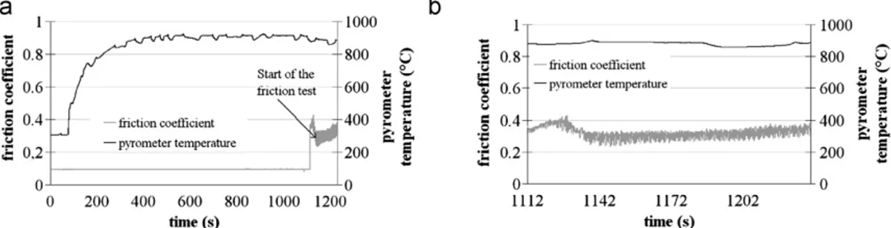
The general representative aspect of the friction behaviour is illustrated inFig. 9a. The disc surface temperature measured by the pyrometer is reported as well as the friction coefficient. As can be observed the temperature increases until 900 1C during the first 5 min. The following 10 min are needed to stabilise the surface temperature of the disc. Then, the temperature remains around (890715) 1C. A very reproducible behaviour is observed for every test.
When the stabilised conditions are reached, the friction test starts. Fig. 9b shows the detailed evolution of the friction coefficient during the first 2 min. The mean value of the friction coefficient is 0.3370.02. The trend shows an increase of the friction coefficient during the first seconds, followed by a decrease leading to a minimum around 25 s. Then the friction coefficient seems to increase slightly until the end of the test. This low mean value of the friction coefficient is consistent with a high tempera-ture contact. The initial contact is metal/oxide. But as the friction starts, the nature of the contact evolves to a oxide/oxide contact because the pin surface is oxidised almost instantly.
3.2. Pin observations
After the friction tests, the pin and the disc are naturally cooled down to room temperature separately (no quenching). The contact surface of the pins is then observed post-mortem
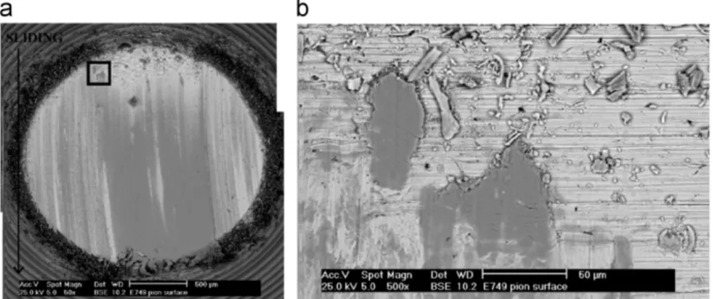
by ESEM. InFig. 10are presented three micrographs of the same pin surface: (a) before the friction test, with all the indentations apparent with the SE mode; (b) after the friction test, with the SE mode, four among the seven initial indentations are seen; and (c) after the friction test, with the BSE mode. For all the pin surface observations presented in this paper, the friction direction is set downward. The BSE observations revealed the presence of a layer with a different composition on the surface of the pin (Fig. 10c). This layer is not uniform on the surface (which is usual in friction tests) and we can still observe some indentations. The other indentations are no longer visible and are actually filled up by third body particles.
Topographical measurements indicate that this third body layer has a thickness of about 3
m
m (Fig. 11). As can be observedSLIDING SLIDING
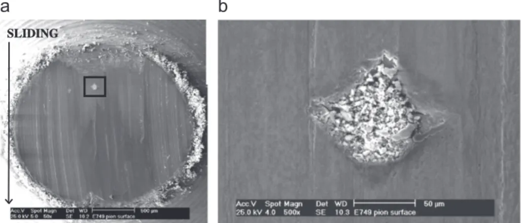
Fig. 16. ESEM observations of (a) the whole contact surface; (b) one indentation filled up with third body particles.
Fig. 18. ESEM observation of the plastic deformation of the metallic pin in an overlaying form.
SLIDING
at the exit of the pin, this layer is actually constituted of two superimposed layers. The outer one is about 1
m
m thick and the inner one is about 2m
m thick. Under this multilayer oxide, the polishing grooves are always visible. The observation of the extremities of the multilayer oxide indicates that a very large plastic flow has occurred over the initial surface. Indeed some cracks presumably leading to the formation of third body parti-cles are observed.Two velocity accommodation mechanisms are emphasised in Fig. 11: The shearing of the oxide scale (S3M3) and the rupture of
this oxide scale (S3M2). These velocity accommodation
mechan-isms will be explained and detailed in Section 3.4. And from now on, this smooth oxide scale observed on the pin surfaces will be referred to as a glaze layer[32].
The plastic deformation of the top glaze surface is highlighted in Fig. 12 where the plastic flow lines are visible. Generally, except at some extremities of the glaze surfaces, no cracks are observed while the plastic deformation flow lines are present. ‘‘Pseudoplasticity’’, as proposed by Sch ¨utze[19], could be at the origin of this large deformation of oxides without cracking because the created cracks are actually healed.
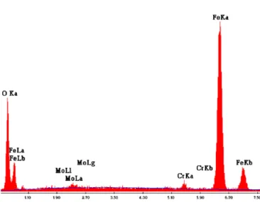
EDS analysis revealed the presence of oxygen, iron, chromium and some other components in the top layer (Fig. 13). If we consider that the analysed volume by the EDS probe concerns also the substrate, the first hypothesis would be that this top oxide layer could be the result of transferred third body particles from the disc oxide scale. But detailed observations of this layer indicated the presence of acicular haematite (Fig. 14). In previous studies, this acicular haematite was only observed in the case of alloy steels [29]. So, the presence of this acicular haematite
suggests that this top layer is composed of oxide from the pin and not transferred oxides from the disc (which would be pure iron oxide). The presence of a developed oxide layer on the pin confirms that the tribological solicitations enhance the oxidation kinetic. It is assumed that the oxidation rate increases with the total free surface of the contact. In addition, it is observed under low cycle fatigue (otherwise cyclic plastic straining) that the oxidation constant of the parabolic oxidation law (
d
¼ kpffiffit) increases as compared to stress-free oxidation of the X38CrMoV5 steel. Therefore one can consider an acceleration of the oxidation rate without drastically changing the oxidation mechanisms.Fig. 20. ESEM observations of (a) the pin surface; (b) the ‘‘comet-shape’’ marks on this pin surface. Fig. 19. ESEM observations of (a) the whole contact surface; (b) the plastic flow of the oxide layer at the pin surface.
Fig. 21. ESEM observation of the local deformation of the metallic asperities at the pin surface.
After these general observations, we will now observe some more detailed phenomena, starting from the contact entry to the contact exit.
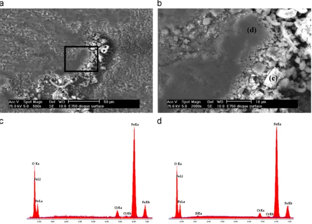
At the contact entry, the loose particles observed could be oxidised particles or oxide particles (Fig. 15). The oxidised particles are third body particles present at first in the contact as metallic particles which are then oxidised while circulating in the contact by plastic deformation, rolling, rupturey. The oxide particles are third body particles coming from the rupture of the glaze oxide layer. The loose particles are constituted of a mixture of compacted (Fig. 15c) and agglomerated (Fig. 15d) small grains. As aforementioned, EDS analysis reveals that they are composed of oxygen, iron and chromium. The presence of chromium indicates that these particles come from the pin.
The particular shape of these particles indicates that they are presumably produced from pin metallic particles which are oxidised in the contact during the friction test. If the particles were produced by the wear of the top oxide layer, the shape will be different and more like flakes. Alike the loose particles at the contact surface, this particular flake shape is only observed at the entry of the pin.
Inside the indentations, the same oxidised particles as those at the contact entry are observed (Fig. 16). It is assumed that these particles are the ones filling the indentations.
Fig. 17shows that at the indentations borders, plastic flow of the metallic pin occurs. It also seems like the metal has been deformed in an overlaying form (Fig. 18). By cumulative plastic shearing, the critical shear ductility of the pin steel is achieved [27] which leads to micro-rupturing and fragmentation of the
Fig. 22. (a) ESEM cross-section observation of an indentation on the pin; (b) EDS spectrum of an oxidised particle from the pin; (c) EDS spectrum of a metallic particle from the pin.
layers to provide metallic particles: The ultimate shear rupture ductile strain, or critical shear ductility, is measured by high temperature torsion tests. These metallic particles could be at the origin of the oxidised particles observed.
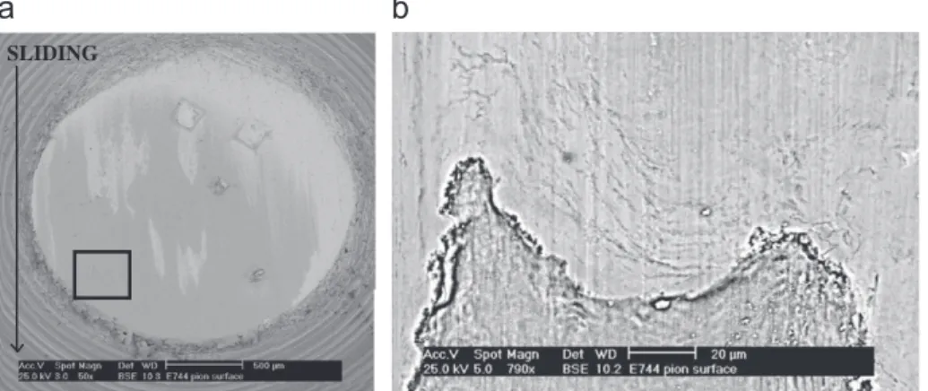
On the contact surface, oxide particles are observed at the contact entry. They are large, totally adherent, compacted and for most of them, plastically deformed to form the glaze layer (Fig. 19). It is assumed that these oxide particles are detached from the glaze layer observed inFig. 11.
Finally ‘‘comet-shape’’ marks are observed on the pin surfaces, presumably indicating that the pin surface has been highly and locally plastically deformed by shearing (Fig. 20). These ‘‘comet-shape’’ marks seem to be formed by the local deformation of the metallic asperities present on the pin surface (Fig. 21). These ‘‘comet-shape’’ marks are oxidised since BSE observations reveal different levels of grey. The oxidation of the pin is very fast since the tribological solicitations on the surface enhance the oxidation rate.
In this case, these ‘‘comet-shape’’ marks cannot be considered as third bodies but as interfacial screens as their chemical composition seems to be different from the first body (they are not metallic) but they belong to the pin surface.
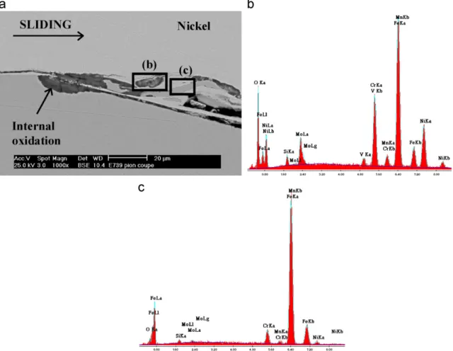
Cross-sections observations of the pin are also undertaken in order to observe what fills the indentations. Two types of third
body particles are observed inside the indentations: Oxidised and metallic particles, both from the pin as EDS analysis shows (Fig. 22). The oxidised particles (Fig. 22b) are rather circular and the metallic particles (Fig. 22c) are very thin and long like fibres (plastic deformation of the lath-shaped microstructure). These particles confirm that the metal itself is significantly deformed under the shear stresses. Internal oxidation is observed at the top surface indentations located at the highly deformed areas. Inter-nal oxidation is also classic for this material[28].
3.3. Disc observations
The wear scars of the disc are also observed by ESEM for each test, in four different places to have a global view of the disc surface. The oxide layer of the disc is constituted, from the oxide/ metal interface to the surface, of w ¨ustite, magnetite and haema-tite. As the disc is not alloyed, the oxide layer microstructure is columnar (Fig. 23a). In the wear track, the superficial haematite seems to be sheared at the top (Fig. 23b). Under the normal load applied, all the contact is carried out by this top layer of haematite. It is then assumed that the whole thickness of the oxide layer is not affected by friction and so, the disc C38 substrate is not either.
Fig. 24. (a), (b) ESEM observations of a glaze zone on the disc surface; (c) EDS spectrum of the oxide wear particle; (d) EDS spectrum of the glaze surface.
Inside the wear track and on its sides, some glaze zones can also be observed (Fig. 24a and b). These areas are composed of agglomerated and compacted oxidised third body particles.
EDS analysis show that these oxidised third body particles come from the pin (Fig. 24c). The composition of the glaze zone is the same as these third body particles (Fig. 24d).
Oxidation Oxidation SLIDING Qr Qw Qe Qi S3M3 S4M3 Initial conditions: Metallic pin X38CrMoV5 Metallic disc substrate C38 Disc oxide scale
SLIDING Qsi Qi Qe Qi Qe Qi Qe Qp SLIDING Qr S3met S3ox Oxidation SLIDING Qw Qi Qe Oxidation SLIDING Qr Qr Qw Qw Oxidation Oxidation SLIDING S1M3 S1M3 S4M3 S4M3 S4M3 S3M3 S4M3 S3M3 M2-M3-M4
Fig. 26. A model of circulation of third body particles inside a high temperature contact. The different steps are (a) initial conditions; (b) local plastic deformation of the pin surface; (c) formation of metallic third body particles from the pin; (d) recirculation and oxidation of the third body particles; (e) shearing of the third body at the pin surface to form the glaze layer; (f) plastic deformation of the glaze layer to cover the entire pin surface; (g) rupture of the glaze layer which lead to oxide third body particles.
The disc roughness profile shows that the wear track corre-sponds to a material loss of the top layer of about 5–8
m
m thick (Fig. 25).As the oxide scale is created before friction during the pre-oxidation step, as its thickness is high (Z 50
m
m) and as the oxide layer is bearing the charge, it can be considered as a first body. It has to be noticed that the superficial haematite sheared at the top of the oxide scale is very thin (E3m
m) compared to the group composed of w ¨ustite and magnetite, and so, will be considered as a tribological screen.3.4. A third body particles circulation model
Based on our numerous observations, the general accommo-dation mechanisms taking place in the friction contact between the pin and the disc at high temperature will be presented. We will give the first steps of the tribological circulation of third body particles. Considering these observations and using the third body concept[24,25], the two first bodies are the metallic pin (S1) and
the oxide scale of the disc (S5), composed only of w ¨ustite and
magnetite. Initially, we can consider only one screen, the super-ficial haematite on the oxide scale of the disc (S4). Based on the
observations, a second screen mentioned as the ‘‘comet-shape’’ marks on the pin surface (S2) is created during friction. The third
body (S3) will concern the metallic particles, the oxidised
parti-cles, the oxide partiparti-cles, and the glaze layers.
Different accommodation mechanisms have been observed on the surfaces. An accommodation mechanism is the combination of one site and one mode of accommodation. According to the third body concept, four modes of accommodation exist. So, the different accommodation mechanisms are as follows:
(i) plastic deformation by shearing of the metallic substrate of the pin (first body-S1M3) (Figs. 17 and 18) which leads to
the rupture of the metallic substrate (S1M2) when the
ultimate deformation is attained. This rupture induces the formation of the metallic third body particles (Fig. 22); (ii) shearing of the metallic pin asperities (S1M3) (Fig. 21) which
leads to the ‘‘comet-shape’’ marks which are also sheared (Fig. 20) (S2M3);
(iii) shearing of the screen on the disc surface (S4M3) which
induces the shearing of the superficial haematite (Fig. 23); (iv) shearing of the third body (S3M3) observed on the pin glaze
layer (Fig. 11);
(v) rolling and/or rupture and/or shearing of the metallic particles present as the pin third body (S3M4/S3M2/S3M3),
mechanisms which transform these metallic particles into oxidised particles;
(vi) plastic deformation of the glaze layer, which is a part of the pin third body (S3M3) (Fig. 12);
(vii) rupture of this glaze layer, which leads to oxide third body particles with a flake shape;
(viii) finally, there is also some transfer material from the pin surface to the disc surface. This transfer is adherent and could be considered as a part of the screen S4 at the disc
surface (Fig. 24).
A scenario of the third body particles circulation inside the contact is proposed, based on the observations, the associated accommodation mechanisms and the third body flows.
The initial contact is metal (pin)/oxide (disc) (Fig. 26a). First, the local plastic deformation of the pin surface leads to the formation of metallic third body particles (Fig. 26b). This is the first internal source of third body which contributes to the internal flow (Fig. 26c). These metallic particles are then oxidised in the contact through the recirculation flow (Fig. 26d).
Two phenomena are then possible: Or these particles stay ‘‘free’’ in the contact, or they are sheared to form spots of glaze layer on the pin surface (Fig. 26e). These spots of glaze layer are plastically deformed so they cover the entire surface (Fig. 26f). If the plastic deformation limit is attained, this glaze layer can break and this rupture leads to the creation of oxide third body particles (Fig. 26g). These oxide third body particles can then be reintro-duced in the contact.
It has to be noticed that the velocity accommodation is mainly taken in charge by the pin surface and the superficial disc oxide scale, whereas the disc metallic bulk is not affected.
In parallel to this scenario, other phenomena which lead to the formation of the glaze layer have to be noticed. The main one is, as explained in the scenario above, the shearing of the pin third body, alike oxidised third body particles and oxide third body particles. The local plastic deformation of the pin steel asperities also induces the ‘‘comet-shape’’ marks and the tribological soli-citations lead to the local pin surface oxidation. We assume that these two phenomena, due to the high stresses present in the contact, act as the first step to form the glaze layer.
4. Conclusion
The global aim of this study was to get a better insight into the circulation of third body particles in a high temperature contact during the first instants of sliding. To achieve this goal, the third body had to be identified, as well as the velocity accommodation mechanisms and the active third body flows. Different unit steps which occur in the contact and lead to the observed phenomena at the end of a friction test are reported. Different types of third body particles (metallic, oxidised and oxide particles) and glaze layers are created.
The shearing deformation of the pin metallic surface occurs in the first seconds of the tribological test and it rapidly competes against the pin oxidation mechanism. Once the oxide scale at the pin surface is created, the tribological contact is carried out by this layer. So we can observe as well plastically deformed areas which result from the shearing of these oxide scales, glaze layers which result from the compaction and the agglomeration of the oxidised particles, and oxidised particles transferred at the disc surface. These mechanisms occur in the first seconds of the tribological contact.
Moreover, it is also shown that the tribological conditions of the tests realised in this study, modify the oxidation kinetics. Indeed, even at medium temperatures and for short oxidation time, X38CrMoV5 steel could be oxidised.
To improve this scenario and to have a better insight into the phenomena taking place during the first instants of sliding, shorter tests have to be made.
References
[1] G. Andreis, K.-D. Fuchs, I. Schruff, The wear behaviour of hot-work tool steels used in forging processes, in: Fifth International Conference on Tooling, Leoben, 1999, pp. 593–600.
[2] O. Barrau, C. Boher, R. Gras, F. Rezaı¨-Aria, Analysis of the friction and wear behaviour of hot work tool steel for forging, Wear 255 (2003) 1444–1454. [3] O. Barrau, C. Boher, R. Gras, F. Rezaı¨-Aria, Wear mechanisms and wear rate in
a high temperature dry friction of AISI H11 tool steel: Influence of debris circulation, Wear 263 (2007) 160–168.
[4] C. Boher, O. Barrau, R. Gras, F. Rezaı¨-Aria, A wear model based on cumulative cyclic plastic straining, Wear 267 (2009) 1087–1094.
[5] M. Busquet, S. Descartes, Y. Berthier, Formation conditions of mechanically modified superficial structures for two steels, Tribology International 42 (2009) 1730–1743.
[6] P.A. Munther, J.G. Lenard, The effect of scaling on interfacial friction in hot rolling of steels, Journal of Materials Processing Technology 88 (1999) 105–113.
[7] O. Joos, C. Boher, C. Vergne, C. Gaspard, T. Nylen, F. Rezaı¨-Aria, Assessment of oxide scales influence on wear damage of HSM work rolls, Wear 263 (2007) 198–206.
[8] C. Vergne, C. Boher, C. Levaillant, R. Gras, Analysis of the friction and wear behavior of hot work tool scale: application to the hot rolling process, Wear 250 (2001) 322–333.
[9] P.J. Blau, T.M. Brummett, B.A. Pint, Effects of prior surface damage on high-temperature oxidation of Fe-, Ni-, and Co-based alloys, Wear 267 (2009) 380–386.
[10] P.J. Blau, Elevated-temperature tribology of metallic materials, Tribology International 43 (2010) 1203–1208.
[11] S.Q. Wang, M.X. Wei, Y.T. Zhao, Effects of the tribo-oxide and matrix on dry sliding wear characteristics and mechanisms of a cast steel, Wear 269 (2010) 424–434.
[12] I.A. Inman, P.S. Datta, Studies of high temperature sliding wear of metallic dissimilar interfaces II: Incoloy MA956 versus Stellite 6, Tribology Interna-tional 39 (2006) 1361–1375.
[13] I.A. Inman, P.S. Datta, Development of a simple temperature versus sliding speed wear map for the sliding wear behaviour of dissimilar metallic interfaces II, Wear 265 (2008) 1592–1605.
[14] I.A. Inman, P.S. Datta, Studies of high temperature sliding wear of metallic dissimilar interfaces III: Incoloy MA956 versus Incoloy 800HT, Tribology International 43 (2010) 2051–2071.
[15] I.A. Inman, P.S. Datta, Studies of high temperature sliding wear of metallic dissimilar interfaces IV: Nimonic 80 A versus Incoloy 800HT, Tribology International 44 (2011) 1902–1919.
[16] I.A. Inman, S. Datta, H.L. Du, J.S. Burnell-Gray, Q. Luo, Microscopy of glazed layers formed during high temperature sliding wear at 750 1C, Wear 254 (2003) 461–467.
[17] M. Sch ¨utze, An approach to a global model of the mechanical behaviour of oxide scales, Materials at High Temperature 12 (1994) 237–247.
[18] R. Von Mises, Mechanik der plastischen form ¨anderung von Kristallen, Zeitschrift f~ar Angewandte Mathematik und Mechanik 8 (1928) 161. [19] M. Sch ¨utze, Plasticity of protective oxide scales, Materials Science and
Technology 6 (1990) 32–38.
[20] J. Jiang, F.H. Stott, M.M. Stack, Some frictional features associated with the sliding wear of the nickel-base alloy N80A at temperatures to 250 1C, Wear 176 (1994) 185–194.
[21] J. Jiang, F.H. Stott, M.M. Stack, A mathematical model for sliding wear of metals at elevated temperatures, Wear 181–183 (1995) 20–31.
[22] J. Jiang, F.H. Stott, M.M. Stack, A generic model for dry sliding wear of metals at elevated temperatures, Wear 256 (2004) 973–985.
[23] M. Godet, The third-body approach: a mechanical view of wear, Wear 100 (1984) 437–452.
[24] Y. Berthier, M. Godet, M. Brendle, Velocity accommodation in friction, Tribology Transactions 32 (1989) 490–496.
[25] Y. Berthier, Experimental evidence for friction and wear modelling, Wear 139 (1990) 77–92.
[26] S. Descartes, Y. Berthier, Rheology and flows of solid third bodies: back-ground and application to an MoS1.6 coating, Wear 252 (2002) 546–556. [27] O. Barrau, Friction and Wear of Hot Work Tool Steels, INP Toulouse, Ph.D.
Thesis, 2004.
[28] P. Bruckel, Oxidation Behaviour of the X38CrMoV5 Tools Steel at 600–700 1C and in Presence of Water Vapour, Mines de Paris, Ph.D. Thesis, 2003. [29] C. Vergne, Oxides Influence on Friction of a Hot Working Cast Iron, Mines de
Paris, Ph.D. Thesis, 2001.
[30] T.F.J. Quinn, J.L. Sullivan, D.M. Rowson, Origins and development of oxida-tional wear at low ambient temperatures, Wear 94 (1984) 175–191. [31] P. Bruckel, P. Lamesle, P. Lours, B. Pieraggi, Isothermal oxidation behaviour of
a hot-work tool steel, Materials Science Forum 461–464 (2004) 831–838. [32] D.J. Barnes, J.E. Wilson, F.H. Stott, G.C. Wood, The influence of oxide films on
the friction and wear of Fe-5%Cr alloy in controlled environments, Wear 45 (1977) 161–176.
![Fig. 1. Velocity accommodation sites and modes in a contact [24,25].](https://thumb-eu.123doks.com/thumbv2/123doknet/11616623.303862/3.892.227.689.897.1131/fig-velocity-accommodation-sites-modes-contact.webp)
![Fig. 6. Square weight gain versus time of oxidation for (a) X38CrMoV5–600 1C and 700 1C [28] and (b) C18–900 1C [29].](https://thumb-eu.123doks.com/thumbv2/123doknet/11616623.303862/5.892.138.711.503.694/fig-square-weight-gain-versus-time-oxidation-crmov.webp)