HAL Id: hal-01063538
https://hal.archives-ouvertes.fr/hal-01063538
Submitted on 13 Dec 2019
HAL is a multi-disciplinary open access
archive for the deposit and dissemination of
sci-entific research documents, whether they are
pub-lished or not. The documents may come from
teaching and research institutions in France or
abroad, or from public or private research centers.
L’archive ouverte pluridisciplinaire HAL, est
destinée au dépôt et à la diffusion de documents
scientifiques de niveau recherche, publiés ou non,
émanant des établissements d’enseignement et de
recherche français ou étrangers, des laboratoires
publics ou privés.
Finite Element Modelling of Alumina-Zirconia Ceramics
under Cyclic Loading Condition
Kyungmok Kim, Bernard Forest, Juliana Uribe, Jean Geringer
To cite this version:
Kyungmok Kim, Bernard Forest, Juliana Uribe, Jean Geringer. Finite Element Modelling of
Alumina-Zirconia Ceramics under Cyclic Loading Condition. Journées Internationales Francophones de
Tri-bologie 2010, 2010, Albi, France. pp.407-416. �hal-01063538�
1
FINITE ELEMENT MODELLING OF ALUMINA-ZIRCONIA CERAMICS UNDER
CYCLIC LOADING CONDITION
MODELISATION PAR ELEMENTS FINIS DE CERAMIQUES ALUMINE-ZIRCONE
SOUMISES A DES CHARGEMENTS CYCLIQUES
Kyungmok Kim¹, Bernard Forest¹, Juliana Uribe¹, Jean Geringer¹* ¹Ecole Nationale Supérieure des Mines de Saint-Etienne, ENSM-SE,
Center for Health Engineering, UMR CNRS 5146, IFR 143 Department of Biomechanics and Biomaterials, 158 cours Fauriel, F-42023 Saint-Etienne Cedex 02 Tel: +(33).4.77.42.66.88; geringer@emse.fr; kkim@emse.fr
Abstract
This paper describes Finite Element modelling of alumina-zirconia ceramics subjected to repeated mechanical shocks. Alumina-zirconia ceramics have been taken account as a promising material of a femoral head and an acetabular cup of artificial hip prosthesis. In this paper, alumina-zirconia ceramics were modelled with an actual microstructure and a cohesive zone law. Simulation conditions were similar to those found at contact between a head and a cup of hip prosthesis. Effects of zirconia, loading magnitude and a void in the microstructure were investigated in terms of crack formation. In addition, fatigue behavior of the microstructure was determined by performing cyclic simulations. Results show that micro-crack initiation and propagation were observed in several regions of a microstructure after cycles.
Key words: alumina, zirconia, crack, wear, finite element method, fatigue, fracture, ceramic
Résumé
Ces travaux concernent une modélisation par elements finis de céramiques alumina-zircone soumises à des chocs mécaniques. Les céramiques alumine-zircone sont considérées comme des matériaux prometteurs pour fabriquer des éléments d’une prothèse de hanche comme une tête fémorale et une cupule cotyloïdienne. Ces matériaux ont été modélisés grâcé à une microstructure réelle et une loi de zones cohésives. Les conditions de simulation furent similaires à celles observées entre une tête et une cupule. Les effets de la zircone, l’amplitude du chargement et la présence de vide dans la microstructure ont été abordés vis-à-vis de la formation de fissures. De plus, le comportement en fatigue de la microstructure a été déterminé. Les résultats montrent que l’amorçage et la propagation des micro-fissures se produisent en différentes régions de la microstructure.
*
2
1. IntroductionAlumina-zirconia ceramic is known as one of promising materials in biomedical engineering. Particularly, Al2O3-ZrO2 (typically with 10% weight of zirconia in an alumina matrix) has been considered as the primary
candidate for a femoral head and an acetabular cup of artificial hip prosthesis. Dispersion of stabilized ZrO2
(3Y-TZP) particles in Al2O3-ZrO2 ceramic leads to the improvement of mechanical properties. Crack formation or loss
of material takes place at a contact surface between a head and a cup in hip prosthesis, since repeated mechanical shocks are imposed on the surface [1]. Failure of artificial hip prosthesis resulting from fatigue or wear might bring about serious damages to a human body. For this reason, degradation of contact damages is one of critical issues in design of hip prosthesis. Several studies were carried out in order to investigate contact damages for hip prosthesis or another part of a human body [2-7]. Fracture and wear of alumina heads or cups of hip prosthesis were macroscopically studied [2,3]. Fracture toughness and wear rate of alumina heads were determined. Severe wear and fracture of zirconia heads against alumina cups was investigated with a hip simulator [4]. Wear rate of a head was measured under micro-separation conditions. Finite Element (FE) modelling of compressive fracture in ceramics was performed [5]. Two-dimensional FE modelling was developed with pure alumina microstructures generated by Voronoi tessellation of randomly positioned seeds. Fatigue crack growth at the micro-structural level was characterized with a stress intensity parameter [6]. A theoretical model describing short-and long-crack growths was built for human bones. Micro-and macro-scale boundary element modelling was performed with polycrystalline Al2O3 ceramic material [7]. Three-point bending was loaded to a
model and crack propagation was investigated.
Several methods for investigating failure behaviour have been considered including fracture mechanics, continuum damage mechanics, and so on. Particularly, a method using cohesive zone laws is mainly used for fracture behaviour of micro-and macro-structures [8], since this method enables simulating fracture of interfaces between physical parts and characterizing post-yield softening. Elements used in cohesive zone modelling do not represent any physical material but contain cohesive forces arising when they are being pulled apart. If these elements satisfy pre-defined damage criterion, cohesive forces are completely deleted. Thus, it is possible to simulate crack initiation and crack growth in a structure. Cohesive zone models have been recently used in biomaterial areas [9-11]. Tension and compression cracks in bone-cement interface were investigated by using cohesive zones [9]. A cohesive fracture model was formulated and used for human femoral cortical bones [10]. A micro-mechanical model was developed for predicting damages for ligament-to-bone attachment in a human knee joint [11]. A cohesive zone model theory was proposed, focusing on the development of behaviour laws for crack initiation and propagation at an interface within a fibrous material or at the interface between materials.
Manufacturing processes for Al2O3-ZrO2 include sintering for ceramic densification [12]. In a sintering process,
a typical temperature range of grains is from 25°C to 1500°C. Difference of grain growth rate exists in Al2O3-ZrO2
microstructure, since thermal expansion coefficients of Al2O3 and ZrO2 are different. Thus, after sintering, the
microstructure maintains residual stresses affecting mechanical behaviours under loading conditions. Meanwhile, the crystallographic structure of ZrO2 is tetragonal and metastable at room temperature. After sintering,
consequently, this metastable structure could be transformed under mechanical shocks, i.e. submitted to adding of energy, from tetragonal to monoclinic. This structural change of ZrO2 (3Y-TZP) grains leads to dilatation
expansion up to approximately 8% in volume. This phenomenon has an influence on crack growth in a microstructure. That is, crack path in Al2O3-ZrO2 structure at microscopic level may be closed during repeated
mechanical shocks between a head and a cup of hip prosthesis.
Finite Element method is effective and widely used for simulating crack initiation and propagation in a structure resulting from external loading. A commercial Finite Element package (ABAQUS®) enables building complex
3
elements (i.e. grains and boundaries) and implementing cohesive zone models. For the purpose of investigating crack initiation and propagation in Al2O3-ZrO2 microstructures, 2D Finite Element modelling with cohesive zone
laws was performed in this paper: an actual Al2O3-ZrO2 microstructure was modelled and meshed. Simulation
conditions similar to those found at hip prosthesis were chosen [2].
2. Cohesive zone laws
In this paper, grain boundaries were described with a cohesive zone law. Cohesive behaviour can be directly defined in terms of a traction-separation law [13]. This cohesive behaviour allows specification of material properties such as relative displacement at failure, the fracture energy as a function of the ratio of normal to shear deformations at the interface. Moreover, the behaviour allows assumption that the failure of elements is characterized by progressive degradation of the material stiffness.
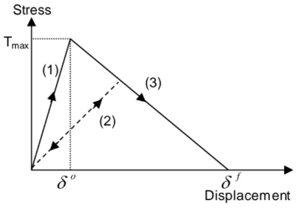
Stress Displacement (3) (2) (1) Tmax o
fFig. 1 Stress versus displacement curve for cohesive zone law
Courbe contrainte-déplacement relative à une zone cohésive
Fig. 1 illustrates the stress versus displacement curve for cohesive zones. Initially, stresses of a cohesive zone increase on line (1) in the curve when external loads are imposed to the cohesive zone. If a stress magnitude remains below the maximum strength value (T max), unloading leads to stress decrease on line 1 (toward the
origin of the stress-displacement plane). If the stress magnitude reaches Tmax (so-called damage initiation) and
then decreases along line 3, unloading subsequent to damage initiation takes place linearly toward the origin of the stress-displacement plane (line 2). Reloading subsequent to unloading also takes place along the same linear path until the softening envelope (line 3) is reached. Once displacement reaches pre-described failure magnitude, stress becomes zero. For the purpose of linear softening, an evolution of the damage variable (D) proposed by Camanho and Davila [14] is used as:
) ( ) ( max max o f o f D (1)
where, f denotes the effective displacement at complete failure, o is relative to the effective displacement at damage initiation, and maxrefers to the maximum value of the effective displacement attained during the loading history. If the damage variable of a cohesive element is equal to unity, the cohesive element is fully damaged and deleted.
4
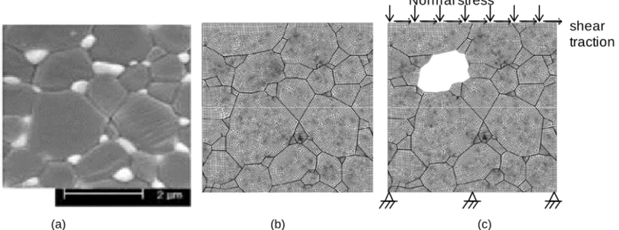
3. Simulation conditionsFig. 2a shows microstructure image of Al2O3-ZrO2 ceramic: white particles are ZrO2 and dark grey ones are
Al2O3. These particles were modeled with data digitalization software and Python programming language.
Normal stress
shear traction
(a) (b) (c)
Fig. 2 Images of (a) Al2O3-ZrO2 microstructure [15], (b) a meshed model, and (c) conditions in a model with a single void Images : (a) microstructure Al2O3-ZrO2 [15], (b) un modèle maillé et (c) les conditions dans un modèle avec une porosité
Fig. 2b illustrates a built model including grains and cohesive zones. The model consists of two kinds of grains (Al2O3 and ZrO2) and cohesive elements between grains. The model size is 5µm
5µm, and the total number ofelements is approximately 15,000: 2,500 cohesive elements and 12,500 grain ones. Commercial Finite Element software (ABAQUS 6.8 standard) was used for simulating models. Each model was simulated on a cluster with 10 calculation nodes (Intel Xeon Quad Core 3GHz, 64 bits with 1GB). In order to induce fast cracks, a single grain was removed from a model as shown in Fig. 2c. A head and a cup in hip prosthesis are subjected to repeated mechanical shock. This shock gives rise to crack formation or loss of material on the contact surfaces of both the head and the cup, defined as contact stresses. Thus, a normal stress and a shear traction on the top surface of a model were applied for reproducing contact stresses. Meanwhile, the bottom surface was fixed while loading was applied as shown in Fig. 2c. A normal stress magnitude varies according to locations within a contact surface, ranging from 5MPa to 500MPa [2]. In this paper, four normal stress magnitudes of 5, 50, 250, and 500MPa were considered. Shear traction was determined with Coulomb friction coefficient of the material (i.e. 0.4 at dry condition and at room temperature). Elastic-plastic behavior was considered for all grain elements. Table 1 shows mechanical properties of grains and table 2 shows materials properties of cohesive layers used in this study. Two distinct cohesive layers were defined: one is placed between Al2O3 grains, and the other is placed
between Al2O3 and ZrO2 grains. The strength magnitude of a cohesive layer defined here is similar to that found
in literature [5,16]. Displacement at failure in the table means total displacement requiring complete failure at each element. Al2O3 ZrO2 Al2O3 vs. Al2O3 Al2O3 vs. ZrO2 Elastic modulus (shear), GPa 374 (153) 210(81) Strength (shear), MPa 1,000 (400) 1,200 (420)
Poisson ratio 0.22 0.30 Displacement
at failure, µm 0.001 0.001
Yield strength,MPa 5,000 2,000 Thickness, µm 0.01 0.01
Tab. 1 Mechanical properties of grains Tab. 2 Material properties of cohesive layers
5
4. Results and discussion4.1. Effect of ZrO2 grains
First, a model with a single void was simulated for investigating the effect of ZrO2 grains in Al2O3-ZrO2
microstructure. Pure Al2O3 and Al2O3-ZrO2 ceramics were loaded at a normal stress of 50MPa and a shear
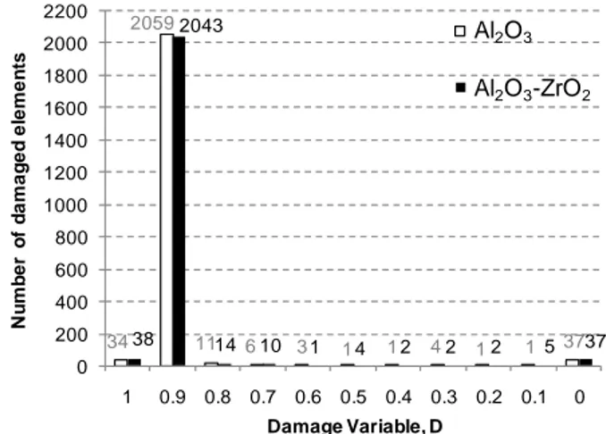
traction of 20MPa. Fig. 3 illustrates the number of damaged elements with respect to material. These results were obtained after the initial cycle consisting of loading and unloading steps. It is found from the plot that addition of ZrO2 into a pure Al2O3 structure brings about four additional cracks. Note that crystallographic structure change of
ZrO2 was not taken into account in this simulation.
34 2059 11 6 3 1 1 4 1 1 37 38 2043 14 10 1 4 2 2 2 5 37 0 200 400 600 800 1000 1200 1400 1600 1800 2000 2200 1 0.9 0.8 0.7 0.6 0.5 0.4 0.3 0.2 0.1 0 N u m b e r of da m a ge d e le m e n ts Damage Variable, D Al2O3 Al2O3-ZrO2
Fig. 3 Number of damaged elements vs. damage variable, D; direct comparison between pure Al2O3 and Al2O3-ZrO2 Nombre d’éléments endommagés vs. variable d’endommagement, D, comparaison entre Al2O3 et Al2O3-ZrO2
4.2. Fracture behaviors of Al2O3-ZrO2 composite with a void
4.2.1. Effect of a void
A normal stress of 50MPa and a shear traction of 20MPa were applied onto the top surface of a model for investigating effect of a void. Fig. 4 shows direct comparison between results with a single void and those without the void. 17 1906 35 10 9 12 9 9 9 12 356 38 2043 14 10 1 4 2 2 2 5 37 0 200 400 600 800 1000 1200 1400 1600 1800 2000 2200 1 0.9 0.8 0.7 0.6 0.5 0.4 0.3 0.2 0.1 0 N u m b e r of da m a ge d e le m e n ts Damage Variable, D Without a void With a void
Fig. 4 Number of damaged elements vs. damage variable, D, direct comparison between results with a void and those without
a void. Grey labels denote the number of damaged elements in a result without a void
Nombre d’éléments endommagés vs. variable d’endommagement, D, comparaison entre les résultats provenant des modèles avec et sans porosité. La couleur grise est relative au nombre d’éléments endommagés pour une configuration
sans porosité
6
calculated by Eq. 1 was determined on the number of damaged elements versus D plot. The D value of unity means that a cohesive element is fully damaged. On the other hand, the value of zero is that the element is non-fully damaged. As shown in Fig. 4, a model with a void maintains cracks two times more than that without a void (at D = 1). Some cracks were observed near the void. This result proves that a void in a model plays a role in giving rise to cracks.
4.2.2. Effect of applied contact stresses
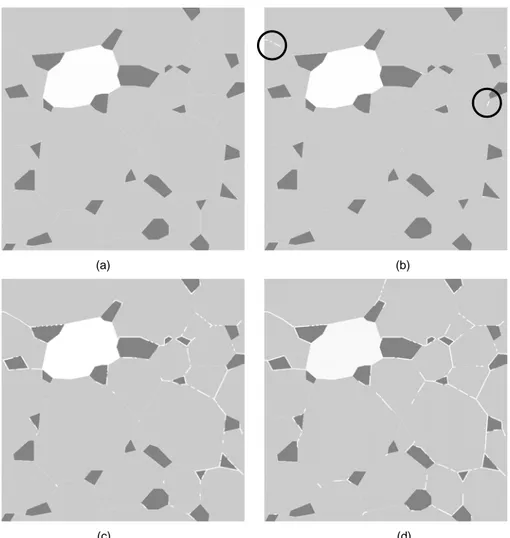
Contact stresses greatly affect crack initiation and propagation in ceramics. A normal stress magnitude between a head and a cup in hip prosthesis at the macroscopic level was measured as 5MPa. On the other hand, at the microscopic level, normal stress magnitudes vary due to roughness of the material. It is found that a maximum normal stress exceeds 500MPa at the contact surface of a cup [2]. In this paper, normal magnitudes of 5, 50, 250, and 500MPa were considered for identifying the effect of contact stresses in a model with a void. The magnitude of a shear traction was calculated according to that of the normal stress under the assumption that friction coefficient is 0.4. Fig. 5 depicts 2D illustrations of crack distributions at different contact stresses.
(a) (b)
(c) (d)
Fig. 5 Illustrations of crack distributions in a model with respect to applied normal stresses: (a) 5MPa, (b) 50MPa, (c) 250MPa,
and (d) 500MPa. White lines denote cracks, dark grey areas are ZrO2, and light grey ones are Al2O3. Circles in (b) highlight crack locations
Images des distributions de fissures dans un modèle en fonction des contraintes normales appliquées : (a) 5 MPa, (b) 50 MPa, (c) 250 MPa et (d) 500 MPa. Les lignes blanches représentent les fissures, les zones grises (gris clair) correspondent
à la zircone (l’alumine). Les cercles, sur l’image (b), mettent en évidence la localisation des fissures
At a normal stress of 5MPa, no cracks are observed within the entire model (Fig. 5a). At 50MPa, it is observed that cracks start to occur (Fig. 5b): a short crack initiates in the upper-left side of a model. Long cracks are
7
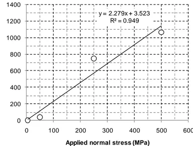
observed at 250MPa and the number of cracks is increased (Fig. 5c). At 500MPa, some long cracks are exhibited at the lower side of the model (Fig. 5d). In addition, the model becomes entirely damaged. Fig. 6 shows the number of damaged elements with respect to normal stress magnitudes. The number of cracks increases with increasing the stress magnitude. 1100 cracks were observed at 500MPa.
y = 2.279x + 3.523 R² = 0.949 0 200 400 600 800 1000 1200 1400 0 100 200 300 400 500 600 N u m b e r of f u lly da m a ge d e le m e n ts
Applied normal stress (MPa)
Fig. 6 The number of fully damaged elements with respect to applied normal stresses
Nombre d’éléments complètement endommagés en fonction de la contrainte normale appliquée
4.3. Fatigue behavior of Al2O3-ZrO2 microstructure
Simulation under cyclic loading conditions was performed. Material properties of grains and cohesive zones were maintained constant during cycles. A normal stress of 50MPa and a shear traction of 20MPa on a model with a void were chosen for creating short and long cracks. Fig. 7 shows 2D illustrations of crack distributions in a model with a void. A short crack was observed after the initial cycle (loading and unloading). Remarkably, a long crack was found in the upper side of a model after 20 cycles. Furthermore, the upper-left grains were completely separated from the model as shown in Fig 7b. Additional cracks were found at the right side of a structure after 45 cycles and a ZrO2 grain was separated (Fig. 7c). After 70 cycles, all of upper grains were completely
separated from a model (Fig. 7d). It could be concluded that repeated contact stresses (normal load of 50 MPa) lead to progressive damages to a microstructure, eventually resulting to grain separation known as wear phenomenon.
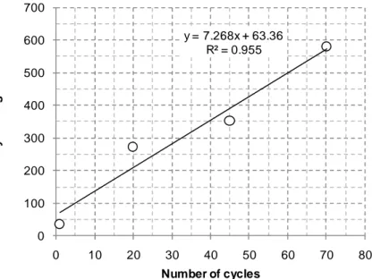
Fig. 8 shows the number of fully damaged elements occurred during cycles. After the initial cycle, 38 elements were fully damaged. The number of fully damaged elements was increased with increasing the number of cycles. After the final cycle, about 600 cracks were observed. Although 600 of 2500 cohesive elements were fully damaged, the number was enough to separate upper grains from a model. These results highlight the fatigue behaviour of the composite Al2O3-ZrO2. Thanks to the comparison between Fig. 8 and Fig. 6, one might suggest
that fatigue behavior after 70 cycles at 50 MPa is almost equivalent to that after the initial cycle at 250 MPa. These results also allow determining, it is a first insight, the fatigue behaviour of the ceramic composite by FE modelling.
8
(a) (b)
(c) (d)
Fig. 7 Illustrations of crack distributions in a model with respect to the number of cycles: (a) cycle 1, (b) cycle 20, (c) cycle 45,
and (d) cycle 70. White lines denote cracks, dark grey areas are ZrO2, and light grey ones are Al2O3.
Photos représentant la distribution des fissures dans un modèle en fonction du nombre de cycles : (a) cycle 1, (b) cycle 20, (c) cycle 45, et (d) cycle 70. Les lignes blanches représentent les fissures, , les zones grises (gris clair) correspondent à la
zircone (l’alumine). y = 7.268x + 63.36 R² = 0.955 0 100 200 300 400 500 600 700 0 10 20 30 40 50 60 70 80 Nu mb er o f f u ll y d a ma g e d el em en ts Number of cycles
Fig. 8 The number of fully damaged elements with respect to cycles.
9
5. ConclusionsThis paper describes fracture behavior of Al2O3-ZrO2 ceramic at the microscopic level (i.e. ceramic grain scale).
Al2O3-ZrO2 ceramic is a promising material for artificial hip prosthesis due to its superb mechanical properties.
Nevertheless, investigation on fracture behavior of the ceramic is rather limited. In this paper, a commercial Finite Element package (ABAQUS®) and a cohesive zone law were used for investigating crack initiation and propagation in a microstructure of Al2O3-ZrO2 ceramic.
A cohesive zone law was implemented for describing an interlayer zone between grains. A femoral head of hip prosthesis transfers external loads to an acetabular cup through frictional contact. At this stage of investigations, under same geometries and loading conditions, significant difference between two materials, pure Al2O3 and
Al2O3-ZrO2 (no crystallographic change of zirconia), was not found in terms of the number of cracks. Void effect in
a microstructure was identified by including a defect of a single grain. It was observed that a defect of a grain in a microstructure leads to additional cracks. At this friction contact, crack formation or loss of material mainly occurs. For this reason, the effect of contact stresses was investigated in terms of crack formation. The number of cracks in a microstructure apparently increases with increasing contact stresses.
It is of importance that fatigue behavior of Al2O3-ZrO2 is investigated at the microscopic level. For the purpose
of this fatigue behavior, cyclic loading was applied to a model built with Finite Element method. Cracks were found in a variety of areas, and crack growth was apparently observed with respect to cycles. Results also show that grains located at the upper side of a model were progressively separated during cyclic loading. This separation of grains could be understood as wear phenomenon.
Residual stresses in Al2O3-ZrO2 ceramic occur due to mismatch of thermal expansion coefficients of grains
after a sintering process of manufacturing. These residual stresses might directly affect crack initiation. In addition, during the sintering process or under mechanical shocks, the crystallographic structure of ZrO2 could be
transformed: from tetragonal to monoclinic. Eventually, this structural change of ZrO2 grains leads to dilatation
expansion. This phenomenon also has an influence on crack growth in a microstructure. Therefore, successive simulations will focus on the modeling of thermal residual stress distribution as well as ZrO2 grain volume growth.
Further analysis will include three dimensional FE modelling with actual microstructures.
Acknowledgements
The authors wish to acknowledge the financial support of ‘ANR’ project. Particular thanks are due to Pr. R. Estevez, Pr. J. chevalier and Dr. L. Gremillard for fruitful discussions.
Reference
[1] Hausselle J., Drapier S., Geringer J., Dursapt M., Stolarz J., Forest B., « Modélisation de la croissance de défauts dans des cupules de prothèses de hanche en zircone soumises au phénomène de décoaptation », Mécanique & Industries, 9 (2008) 153-158.
[2] Hausselle J., «Etude de la dégradation par chocs de têtes et cupules de prothèses de hanche en biocéramique », PhD thesis N° 458SGM, Ecole Nationale Supérieure des Mines de Saint-Etienne, 2007.
[3] Geringer J., Forest B., Combrade P., « Wear analysis of materials used as orthopaedic implants », Wear, 261 (2006) 971-979.
[4] Stewart T.D., Tipper J.L., Insley G., Streicher R.M., Ingham E., Fisher J., « Severe wear and fracture of zirconia heads against alumina inserts in hip simulator studies with microseparation », The Journal of Arthroplasty, 18 (6) (2003) 726-734. [5] Warner D.H., Molinari J.F., « Micromechanical finite element modeling of compressive fracture in confined alumina ceramic
10
», Acta Materialia, 54 (2006) 5135-5145.[6] Taylor D., « Modelling of fatigue crack growth at the microstructural level », Computational Materials Science, 25 (2002) 228-236.
[7] Sfantos G.K., Aliabadi M.H., « Multi-scale boundary element modelling of material degradation and fracture », Computer Methods in Applied Mechanics and Engineering, 196 (2007) 1310-1329.
[8] Nguyen O., Repetto E.A., Ortiz M., Radovitizky R.A., « A cohesive model of fatigue crack growth », International Journal of Fracture, 110 (2001) 351-369.
[9] Clech J.P., Keer L.M., Lewis J.L., « A model of tension and compression cracks with cohesive zone at a bone-cement interface », Journal of Biomechanical Engineering, 107 (2) (1985) 175-183.
[10] Yang Q.D., Cox B.N., Nalla R.K., Ritchie R.O., « Fracture length scales in human cortical bone: The necessity of nonlinear fracture models », Biomaterials, 27 (2006) 2095–2113.
[11] Subit D., Chabrand P., Masson C., « A micromechanical model to predict damage and failure in biological tissues. application to the ligament-to-bone attachment in the human knee joint », Journal of Biomechanics, 42 (2009) 261–265. [12] Ye Y., Li J., Zhou H., Chen J., « Microstructure and mechanical properties of yttria-stabilized ZrO2/Al2O3 nanocomposite ceramics », Ceramics International, 34 (2008) 1797-1803.
[13] ABAQUS 6.7 Documentation, ABAQUS Inc: USA, 2007.
[14] Camanho P.P., Davila C.G., « Mixed-mode decohesion finite elements for the simulation of delamination in composite materials », NASA/TM-2002-211737, 2002.
[15] Gutknecht D., « Elaboration et caractérisation de micro- et nano-composites alumine-zircone pour application orthopédique », PhD thesis N° 2006ISAL0067, INSA de Lyon, 2006.
[16] Yasuda K., Tatami J., Harada T., Matsuo Y., «Twist angle dependence of interfacial fracture toughness of (0001) twist boundary of alumina », Key Engineering Materials, 161-163 (1999):573-576.