HAL Id: hal-01349723
https://hal-mines-nantes.archives-ouvertes.fr/hal-01349723
Submitted on 28 Jul 2016
HAL is a multi-disciplinary open access
archive for the deposit and dissemination of
sci-entific research documents, whether they are
pub-lished or not. The documents may come from
teaching and research institutions in France or
abroad, or from public or private research centers.
L’archive ouverte pluridisciplinaire HAL, est
destinée au dépôt et à la diffusion de documents
scientifiques de niveau recherche, publiés ou non,
émanant des établissements d’enseignement et de
recherche français ou étrangers, des laboratoires
publics ou privés.
Turbulent Flows Structures Crossing Conical Diffusers:
Angle Effect Analysis using PIV Technique and POD for
Post-Processing
Emna Berrich, Fethi Aloui, D Pierrat, L Gros, A Couzinet, Jack Legrand
To cite this version:
Emna Berrich, Fethi Aloui, D Pierrat, L Gros, A Couzinet, et al.. Turbulent Flows Structures Crossing
Conical Diffusers: Angle Effect Analysis using PIV Technique and POD for Post-Processing. Journal
of Applied Fluid Mechanics, Elsevier, 2016, 9 (1), pp.19-29. �hal-01349723�
Journal of Applied Fluid Mechanics, Vol. 9, Special Issue 1, pp. 19-29, 2016.
Selected papers from the 7th
International Exergy, Energy
and Environment Symposium, IEEE7-2015
Available online at www.jafmonline.net, ISSN 1735-3645, EISSN 1735-3645.
Turbulent Flows Structures Crossing Conical Diffusers:
Angle Effect Analysis using PIV Technique and POD for
Post-Processing
E. Berrich
1, F. Aloui
2†, D. Pierrat
3, L. Gros
3, A. Couzinet
3and J. Legrand
41 GEPEA - UMR CNRS 6144, Ecole des Mines de Nantes, EnergeticSystems and Environment Department,4 Alfred KASTLER Street- BP20722 Nantes, France
2 University of Valenciennes (UVHC), LAMIH CNRS UMR 8201, Department of Mechanics,Campus Mont Houy, F-59313 Valenciennes Cedex 9, France
3 Centre Technique des Industries Mécaniques de Nantes (CETIM), 74 route de la Jonelière - 44300 Nantes, France
4 LUNAM Université, Université de Nantes, CNRS, GEPEA UMR6144, CRTT, BP 406,37 Boulevard de l’Université - 44602 Saint-Nazaire Cedex, France
†Corresponding Author Email: [email protected] (Received October 20, 2015; accepted December 10, 2015
A
BSTRACTIn this work, we investigated experimentally the hydrodynamics of flows crossing conical diffusers. On our previous work (Aloui et al., 2011), CFD turbulent models were validated for flows crossing the critical angle (2=16°). Indeed, the PIV data base constructed was exploited to validate a variant of SST-RLC model. Taking into account the conical diffuser angle effect, the apparition and the development of vortices were observed and studied. The dynamics of the recirculation zones which may be observed at the lower and higher parts of the singularity, has not formed the subject of numerous studies. There were no studies that characterize the vortices at the conical diffusers in terms of size, centre positions, and vortex intensity. Consequently, two conical diffusers were studied using the Particle Image Velocimetry technique (PIV). The results illustrate effects of “opening angle” (2=16°) and (2=30°) on the flow structures developed in such type of diffusers. From such opening angle of conical diffusers, the progressive angle increasing generates a detachment of the boundary layer of the conical diffuser depending on the turbulence level. This detachment may lead to a coherent flow structures. We applied the coherent structures criterion 2 to the recorded velocity fields to detect and characterize the vortices at the conical diffusers. We used the Proper Orthogonal Decomposition (POD) to filter the PIV data base constructed and to extract the most energetic modes. The results illustrate that the turbulent flow structures can be constituted using a limited number of energetic modes.
Keywords: Conical diffusers; Opening diffuser angle; Flow dynamics; Turbulence; Coherent structures; PIV
Technique; 2 criterion; Proper Orthogonal Decomposition POD.
N
OMENCLATUREai,j temporal coefficient relating to a mode S the surface which surrounds the point P,
D measurement field t time,
Dh upstream hydraulic diameter u axial velocity component p
d polyamide diameter v radial velocity component K temporal correlation matrix of the Velocity field ub mean inlet velocity
L length X,Y,Z coordinates
Q second invariant n normal vector in the measurement plan M point of the wide S λ proper value of the matrix,
N number of snapshots δi,j coefficient,
p pressure 2 kinematic criterion,
E. Berrich et al. /JAFM, Vol. 9, Special Issue 1, pp. 19-29, 2016.
20
POD Proper Orthogonal Decomposition ρ density
Rc curvature radius of elbow Ω vorticity vector The surface which surrounds the point P
Re Reynolds number
1. INTRODUCTION
Whether in the fields of energy, chemical engineering, food processing, or more generally in the capital foods industry, the extreme increase of industrial facilities production constraints such as cost, reliability, safety, performance, durability, requires a precise understanding of flows structures through a network of processing elements. Conical diffusers, frequently re-encountered on factories, can modify the flow structures and can generate vortices which, if sufficiently developed, may affect the performance of the production or cleaning in place processing or may even lead to the early exhaustion of the process circuits. The appearance and the amplification of vortex structures involve significant kinetic energy or significant oscillations in the flow or highly asymmetrical recirculation zones.
We focus on turbulent flows structures in conical diffusers by studying experimentally the behaviour of turbulent flow crossing two conical diffusers with opening angle respectively equals to 2α = 16 ° and 30°. This provides a profile of established flow (L/Dh>> 70).
Few studies have been interested to diffusers, either by numerical or experimental approaches. Regarding the first approach, the diffuser was generally considered as isolated element. The problem was reduced to a symmetric or axisymmetric form (Armfield and Fletcher, 1989). Edimilson et al. (2004) studied numerically turbulent flow in small-angle diffusers and contractions using a new wall treatment and a linear high Reynolds κ-ε model. The turbulent flow field was confined in a circular duct with varying cross section. Both expansions and contraction sections were investigated. Equations of boundary-layer type were used and the linear κ-ε model, in its high Reynolds form, was applied. This can limit the representatively of the predicted three-dimensional structures. In experimental studies, the authors do not consider that either moderate angles <16 ° (Cockrell and Bradley, 1971; Spencer et al., 1995) or are restricted to high values of Reynolds number (Re> 1.5 105,Okwuobi et al., 1989), or still consider
the output of the diffuser as free (Okwuobi et al. 1989; McDonald and Fox, 1971). However, for lower values, the flow through a conical diffuser with opening angle 16 ° may reveal a tendency to cause an intense stable vortices but limited compared to the periphery of the diffuser, a relatively small angular sector (Okwuobi et al. 1989). This phenomenon rarely discussed for conical diffusers, may be closer to the asymmetry observed for planar diffusers (Kline, 1959; Johnston, 1998). However, the specific geometry of the latter makes it difficult to transpose the analysis of their behaviour to that of conical diffusers. To study the hydrodynamic behaviour of the diffuser,
especially the variation of the velocity profile, the researchers has focused mostly on the effect of "swirl" considering that the diffuser exit is free (McDonald and Fox, 1971; Clausen, 1993). Meyer and Nielsen (2004) have more recently looked at the effect of a deviation of the incident flux on the flow at the outlet of the diffuser, generated by a deflection angle of 30 ° elbow placed at the inlet diffuser, but have limited their analysis to output plane (Meyer and Nielsen; 2004).
Most of theoretical studies are interested to planar diffusers. The few studies found for conical diffusers include studies for moderate angles less than 16° or more than 16° (Cockrell and Bradley, 1971; Spencer et al., 1995; Johnston, 1998) with large Reynolds numbers (more than 15 104) or
consider the diffuser exit as being free (Okwuobi and Azad, 1973; Mc Donald and Fox, 1971). All these works consider that the turbulent flow is fully developed in the inlet of the diffuser. For non developed turbulent flows in the upstream of confined axi-symmetric diffusers, no experimental study was found for the critical angle (2=16°). In addition, more interest has been conserved to this particular singularity. On our previous primary work (Aloui et al., 2011), we have qualified the setup and validate CFD turbulence model.
A series of data base including PIV measurements, POD post- processing and structures detection criterions has been constituted for the conical diffusers of “opening angle” (2=16°) and (2=30°); specially designed for this work. The paper proposes an answer to the questions “How does the opening angle affect the hydrodynamic structures of flows crossing conical diffusers?”; “What are the size, the centre positions, and vortex intensity which characterize the vortices at the conical diffusers?”
2. EXPERIMENTAL FACILITY
Nowadays, computer control and data analysis software package are available. In this work, a specially designed setup was constructed for the study of the angle effects of conical diffusers on flows crossing it. We have used the “DANTEC” software “Flow Manager” for the PIV measurements.
2.1 Experimental facility and measurement
techniques
The test apparatus is schematically displayed in Fig. 1a. It includes a hydraulic test-section, a tank, a heat exchanger, two parallel electromagnetic flow meters, a pump, and a frequency variator. The hydraulic test-section is made of transparent Plexiglas. The choice of this material is justified by the laser technique used, the Particles Image Velocimetry PIV technique. The diffusers have
E r L L i a c I g t a c t g i t T n i u s t l u t o e I E. Berrich et al. respectively an L=75mm and a L=41mm. The u is Dh= 41mm.
angle affects the conical diffusers It allowed realiz geometrical con to assure that th adapted to the conical diffusers that ensures a geometries (Fi integrated in a c tank (4m3), in The “Velocimetr non-instructive instantaneous v used for measu section of the co the instantaneou localizations. T upstream of the the total section one is located enlargement. In practice, the /JAFM, Vol. 9, angle 2α=16° an angle 2α=30 upstream diamete We determined e structures of f s. A specific con zing PIV measu nfigurations. The e experimental d different angle s. Fig. 1b shows perfect alignme g. 1b). The closed-circuit w order to gua Fig. 1. Hyd (b) Test ry by Image of P technique u velocity field. T urements in a onical diffuser in us velocity field The first one conical diffuser of the conical d downstream velocity of mi Special Issue 1, ° with a length 0° with a length
er of the test sec d how the ope flows crossing t nception is adop urements in diffe e idea behind th
device can easil s, by replacing s the specific de ent of the diffe whole section with a large capa arantee an effic
draulic channel t section and con
Particles” (PIV) used to pro This technique longitudinal cr n order to determ d in three partic is located on r. The second on diffuser and the t of the progres icron-sized parti , pp. 19-29, 2016
21
h of h of ction ning these pted. erent his is ly be g the evice erent n is acity cient degasi bubble is ma heat e two p accura pump, around freque been p 100), condu a full diffuse l: (a) Schematic nical diffusers ( ) is a ovide was ross-mine cular the ne is third ssive icles follow particl are use To ap flow h laser. diffuse the pu a puls CCD (Dante object 6. ification of the es. The used flui intained constan xchanger. The f parallel electrom acy of 0.5% fo , which has a d its optimal op ency variator. A placed upstream where Dh is thuct in the upstrea ly developed t er (Dh=2*R1).
c view of the ins (2α=16° and 2α
wing the flow les of polyamid
ed.
pply the PIV te has to be lighted
The recordin ers of light nec urpose, the PIV s sed Nd-Yag 15 camera of 1 ec Dynamics Flo tive Nikon (60 e turbulent flow id is water, and i nt at 20
0.5°Cflow rate is meas magnetic flow m or the measured power of 2.5 peration output A sufficient strai m of the test se he hydraulic di am of the singul turbulence ups tallation, α=30°). is measured. des, with diame
echnique, the cr d with a lumino g of the disp essitate a specia system used wa mJ laser (New 1600-1186 pixe ow Sense M2/E 0 mm) and a w from small its temperature C thanks to a sured by using meters with an d ranges. The kW, is placed points using a ght length has ection (L/ Dh> iameter of the larity, ensuring tream of the In our case, eters dp20 m ross-section of ous plane via a
placement by al camera. For s composed of wave Solo), a els resolution 8 bit) with an a “DANTEC”
E. Berrich et al. /JAFM, Vol. 9, Special Issue 1, pp. 19-29, 2016.
22
correlator. The whole system is driven by the “DANTEC” software “Flow Manager”.
The flow field’s area studied is the central section of the conical diffuser. For this position, the horizontal laser plane was reflected vertically at z = 0 using a 45° mirror. The CCD camera was placed in front of the lighted diffuser section. For the treatment of measurements, two interrogation areas were been tested: 32 x 32 pixels and 16 x 16 pixels. A comparative study of the treatment results obtained allows choosing 32 x 32 pixels interrogation areas for the study. The PIV measurements are done in three principals positions: in the singularity, upstream and downstream of it. The choice of the measurements plan to position the laser plane and CCD camera is delicate. Indeed, this depends on the localization of the turbulent structures. For certain cases and reasons of checking the appearance of the recirculation zones, series of measurements are added for moderated Reynolds numbers in two other zones of the test section.
2.2. Coherent structures and POD
technique
Chassaing (2000) made a synthesis of several definitions of coherent structure concept: “Anthony Perry, taking a suggestion of John Lumley, defines coherent structure as being recurring reasons for the flow. That does not imply the concept of order, the scales velocity can be unsystematic, but the reasons must have fixed characteristics of orientation to which they become identifiable. It is, according to Kline, of the recurring events which are essential with dynamics such as the production of Reynolds tensions, kinetic dissipation of turbulence energy, and the entities which ensure a momentum transport according to Stull. Wygnanski defines it as being the prevalent mode of instability”. In practice, many criteria are used (Haller, 2005). They play an important role in the study of generation and dissipation mechanisms in fluid mechanic problems. They are usually deduced from the velocity gradient tensor. Among all coherent structures identification techniques, Proper Orthogonal Decomposition (POD) is one of the most objectives, because it does not make assumptions on the flow (Aloui et al. 2007; Aloui
et al. 2008). The first experimental application was
carried out by Payne and Lumley (1967). Sirovich (1987) introduced the Snapshots method, which is carried out classically from the data characterized by an important space resolution and a few temporal resolutions (measurements PIV unsolved in time). The POD is a promising technique thanks to its various advantages (Rehimiet al. 2011). Indeed, it is optimal in term of energy conservation, and requires only the provision of the flow velocity data. It permits to compress data because a reduced number of modes is enough for well describing and rebuilding the flow structures. These various modes resulting from the decomposition can have a physical direction especially in the presence of coherent structures in the flow.
The analysis of the major structures of turbulent flows crossing the conical diffusers is realized. The determination of the flow coherent turbulent structures was of a big interest.
The vorticity vector is one of the criteria most easily accessible to visualize the turbulent structures of the flow. It permits the measure of the flow rotation rate. Its direction, specifying the rotation axes, is written:
V
(1)
whereVis the velocity vector, is the rotational operator, and
indicates the vector product. Strawn et al. (1999) defined the vortex centre as being a local maximum of the vorticity module. In 2D, the vorticity
is written as follows:1 v u
( x, y )
2 x y
(2) The swirl centre is identified as a local extremum of the vorticity function.
Taking in consideration the swirl local convection, the 2criterion is defined as follows:
M
2 M M S PM U u .Z 1 P dS S PM . U u
(3)where the local velocity of convection is written as: S 1 u UdS S
(4)The 2criterion is a Galilean invariant (Graftieaux et al., 2001).
The objective of 2 criterion is to extract the turbulent structures based on their rotations in the flow, because the vorticity does not make it possible to distinguish between shearing and rotation.
At the momentt , the velocity field k U( x, y,t ) k is written:
N
(i ) (i )
k m k
i 1
U( x,y,t ) U ( x,y)
a (t )
( x,y)
(5)
where the coefficient of projection a ( t )( i ) k
checking the following relation:
N ( i ) ( j ) k k i ij k 1 a ( t ) a ( t )
(6) To suitably filter the various velocity fields measured by PIV, the decomposition can be limited to M modes.According to Sirovich (1987), the POD is a good technique if the number of modes M verifies:
E. Berrich et al. /JAFM, Vol. 9, Special Issue 1, pp. 19-29, 2016.
23
M i i 1 N i i 1 90%
(7)where N is the number of Snapshots (velocity fields obtained by PIV).
The POD decomposition permits to filter the PIV measurements: M (i ) (i ) f m i 1 M (i ) (i ) f m i 1
U ( x,y,t ) U ( x,y) a (t ) ( x,y) ( x,y,t ) U ( x,y) a (t ) ( x,y)
(8)3. RESULTS AND DISCUSSION
The main purpose of this paper is to illustrate the conical diffusers opening angles effects on the structures of the turbulent flows crossing it, as it is a topic source of vortex creation. In fact, they may generate the apparition and the development of repetitive and stable vortices. In addition, two configurations are adopted: The first one corresponds to a conical diffuser with an opening angle equal to 2α=16°. The second configuration
corresponds to 2α=30°. More interest has been
conserved to the conical diffuser (2α=16°) as it
presents a critical case i.e no results for this kind of conical diffusers have been found in the literature. In fact, few studies found for conical diffusers include studies for moderate angles less than 16° or more than 16° with large Reynolds numbers (more than 1.5 105) (Cockrell et Bradley, 1971; Spencer et
al., 1995; Johnston, 1998, Jiang et al., 2008; Lee et al., 2012) or consider the diffuser exit as being free
(Okwuobi and Azad, 1973; Mc Donald et Fox, 1971). All these works consider that the turbulent flow is fully developed in the inlet of the diffuser. For non developed turbulent flows in the upstream of confined axi-symmetric diffusers, no experimental study was found for the critical angle (2=16°). In addition, a series of PIV data has been realized. In particular, on the conical diffuser
2α=16° specially designed for this work. It allows
the determination of the instantaneous fields’ velocity. We have used the data base constructed to validate CFD simulations. The accuracy of the PIV measurments is about 1% to 2%. The results are obtained from the temporal average (1500 fields).
3.1. Structures of flows crossing conical
diffusers
The iso-values lines of the axial component velocity, the iso-values lines of the RMS of the axial component velocity and the iso-values lines of the Reynolds tensor in the conical diffuser (2=16°) for a Reynolds number Re=37000, are presented respectively in Figs. 2. a, 3. a and 4. a. While Figs. 2.b, 3.b and 4.b show the results in the conical diffuser (2=30°).
The Reynolds tensor is defined as:
' ' ij
R u v (9) The figures show mainly three different regions in the singularity whatever the opening angle considered. The first region was observed in the approximate of nearly aty / R1 0.75 from the wall in the direction of mean flow. The second region corresponds to the zone where the pressure gradient is important i.e. at the upper part of singularity. The third region is the lower part near the wall where the pressure gradient is less. This let one deduce that there is a slight dissymmetry of the flow. When the conical diffuser’s section increases progressively; the turbulence level in the singularity increases. Even in the presence of this slight dissymmetry, the turbulence level visualized in the conical diffuser (2=16°) does not generate repetitive and stable vortices. However, when the diffuser opening angle is increased twice i.e. (2=30°), fromr / R1 0.4, the iso-values lines of the axial velocity component have a strong curvature, change directions and generate two circulation zones at the upper and lower part of the diffuser. To conclude, for turbulent flows, when the opening of a symmetrical diffuser exceeds a significant angle, an important separation of the boundary layer of the wall appears. Generally, it induces the formation of a stable recirculation zone characterized by negative values of the axial velocity component close to the wall (Yang and Hou, 1998; Braga and de Lemos, 2004; Mondal et al. 2004). In a perfectly axi-symmetric diffuser
with a great angle (in our case, 2=30° and a
length of 41mm, a separation alternatively occurs
in the top and in the bottom sides. It produces strong vibrations of the flow. This detection is in agreement with the observations of Idel' ick (1969) for diffusers having large point angles, going up to
50 at 60°. The comparison of turbulent flows
behaviours in the diffusers (2α=16°) and (2α=30°)
lets deduce that the separation of layers is accompanied by the formation of symmetrical recirculation zones consisted of repetitive and stable contra-rotating swirls when the angle of the diffuser becomes important.
3.2. Velocity profiles of turbulent flows
crossing conical diffusers
The unsteady nature of the flow does not allow an easy interpretation of the charts presented on the preceded section. For more understanding of the opening angle effect on the flow structures variations, we carried out the velocity profiles at different positions along the conical diffusers. This choice was governed by a desire to illustrate the possible apparition of recirculation zones on the diffusers. It allows the localisation of the probable positions of existence of such bifurcations. Indeed, Fig. 5, 6, 7, 8, 9, 10 and 11 demonstrate the velocity axial component profiles along the conical diffusers for Re=37000; respectively at the entry of the diffusers, then at 0.234, 0.42, 0.598, 0.79, 0.88 and 0.97 of the conical diffuser length: (a) (2=16°); (b) (2=30°).
E. Berric Fig. Fig. 3 These di velocity illustrate velocity principle with ope of the p axis, re amplifie dissymm higher a vicinity, ch et al. /JAFM 2. Iso-values Li . Iso-values Lin Fig. 4. Iso-va ifferent plots sh profiles along es particular slightly shifte e flow axis. Inde ening angle (2= rofiles, observed eveals that the ed by the a metry, even if it and lower parts o
the velocity a
M, Vol. 9, Special
ines of the axial
nes of the RMS
alues Lines of th
how the evolut g the conical shapes with ed upward relat
eed, for the coni =16°), the slight d compared to t flow dynamic appearance of
is not the same of the diffuser. are lower but st
l Issue 1, pp.
19-24
l component vel
of the axial com (2=3 he Reynolds ten (a) (2=16° tion of the diffuser. It maximum tive to the ical diffuser asymmetry the diffuser cs are not a strong e one in the At the wall till positive -29, 2016.
4
locity for Re=37
mponent velocit 30°).
nsor of the conic °); (b) (2=30°). both above an no recirculatio the wall for th conditions of asymmetry of to the central flow dynamic the upper an opening angl twice (2=30 velocity axial bottom of the 7000: (a) (2=1 ty for Re=37000
cal diffuser for R .
nd below, which on zone in the i his type of conic f the flow te f these profiles, o
axis of the singu cs on the expansi nd lower parts. e of the conic 0°), there are ne l components, in close zones to th 6°); (b) (2=30 0: (a) (2=16°); Re=37000: h proves that th immediate vicin cal diffuser, und ested. However observed with re ularity, shows th
ion is not the sa However whe cal diffuser incr
egative values o n the top and i he wall. This pro
°). (b) here is nity of der the r, the espect hat the ame in en the reases of the in the oves
E F o E. Berrich et al. Fig. 5. Velocity beginning of th x/Dh = 0: Fig. 6.Velocity of the conical di (a) (2=16°): /JAFM, Vol. 9, y axial compon he conical diffus (a) (2=16°); (b axial componen iffuser length fo x/Dh= 0. 4; (b) ( 0.196. Special Issue 1, nent profile at th ser for Re=3700 b) (2=30°). nt profile at 0.2 or Re=37000: (2=30°): x/Dh , pp. 19-29, 2016
25
he 00, 234 = Fig. 7 Re=37 Fig. 8 of th (2= 6. 7. Velocity axia of the conica 7000:(2=16°): x/D 8. Velocity axial e conical diffus =16°): x/Dh = 1. al component pr al diffuser length x/Dh = 0. 709; ( Dh = 0.354. l component pro ser length for R0227; (b) (2=3 0.5111. rofile at 0.42 h for (b) (2=30°): ofile at 0.598 Re=37000:(a) 30°): x/Dh =
E. Berric Fig. 9. V of the co (a) (2 Fig. 10. of the co (a) (2= ch et al. /JAFM Velocity axial c onical diffuser l =16°): x/Dh = 1 0. Velocity axial onical diffuser l =16°): x/Dh = 1. 0 M, Vol. 9, Special component pro length for Re=3 .338; (b) (2=3
.6687.
component pro length for Re=3 .4963; (b) (2=3 0.747. l Issue 1, pp.
19-26
file at 0.79 37000: 0°): x/Dh = ofile at 0.88 37000: 30°): x/Dh = -29, 2016.6
Fig. 11.Veloc of the end of (a) (2=16°) clearly the exi 10 and 11 (b axial velocity the formation characterized3.3. Vortex
The vorticity in a turbulent vorticity ω i (2=16°) and processing for (a) and (b). T of the flow, t behavior of th i.e. diffuser mechanism of fully develo visualization i low angle (2 the global dyn and below, from a f the cone. Th appears a litt the co asymmetry alr the Idelc'ick d structures are creation of a s zone. Whilecity axial compo the conical diff ): x/Dh = 1.634; 0.806. istence of a recir b)). Thus, the ne component clo n of a stable by (Yang and H
criterion of de
allows the vi t flow. The insta in the conical d (2=30°) obtai r Re=37 000 are The charts of inthrough the sing he boundary lay (2=16°) evol f vortices, witho oped recirculati in the progressiv =16°) revealed namics with a d a length of about his separation is tle early at the b one. This ready detected in deductions (
not observe stable and well d
a stable and
onent profile at fuser for Re=37
(b) (2=30°): x rculation zone (F egative values o se to the wall in e recirculation Hou, 1998).
etection
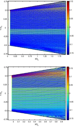
isualization of v antaneous fields diffusers respe ined after the PI e presented in F stantaneous vor gularity, show th yer in the critica lves to a conv ut revealing stab ion zone. Th ve expan a slight disturba detachment both t ¼ of the total le s more significa bottom than theis due n accordanc (1969). The ed and followed developed recircu fully develope t 0.97 000: x/Dh = Fig. 9; of the nduce zone vortices of the ectively IV data Fig. 12 rticityω hat the al case vection ble and he flow nsion of ance of h above ength o ant and top of to the ce with vortex d by the ulation ed one
E a l p d p T d p u b T a f ( i d o l v r d c c t u s a s c d ( E. Berrich et al. appears in the c layers separatio phenomena are difference acros pressure gradien Fig. 12. Sa instantaneous Re=37000 The use of th detecting vortex presence of sign use of the 2
because they are
The instantaneou after the post-pr for Re=37000 re (2=16°) and t illustrated on Fi diffuser (2=16° of turbulence a layer near the w vortex but n recirculation zon detachment wit comparing the criterion obtaine to this obtained under the same strongly devel appears in the fi strong level of caused the app dissymmetrical (2=30°). /JAFM, Vol. 9, onical diffuser ( on and the related to the p ss a given sect nt along the flow
mpling of detec , in isolated co 0: (a) (2=16°); he vorticity as structures is nificant shear w criterion is g e not sensitive to us field of the rocessing of PIV espectively for t the conical dif ig. 13. The resu °) show the pres and detachment wall with a con not necessary nes) . As it can thout stable tur instantaneous ed for the conica for the conical conditions, we loped dissymm irst one while in
turbulence is d parition of a s structure in Special Issue 1, (2=30°). The vortices forma presence of velo tion and a pos w. ction criterion, onical diffusers (b) (2=30°). a criterion not suitable in all. In this case generally prefer o shear.
2 criterion obtain
V data on 7 lay the conical diffu ffuser (2=30°) ults for the coni sence of high lev t of the bound ncrete existence y repetitive be seen, there i rbulent zones. field of the al diffuser (2=1 l diffuser (2=3 e conclude that metrical struct n the second one detected and wh strongly develop the singular , pp. 19-29, 2016
27
sub-ation ocity itive for n for the , the rable ned yers user ) is ical vels dary e of (no is a By 2 16°) 30°) no ture e, a hich ped rity3.4. P
The in the po modes respec Fig. 1 the afte and2 seen, concer instant the c proces superi when zones vortici conica fully a result decom the P treatm illustra resulti turbul the ex flow w post-p being allowe dimen4
r/ R1 -1.5 -1 -0.5 0 0.5 1 1.5 r/ R1 -1.5 -1 -0.5 0 0.5 1 1.5 6.Proper Orthog
nstantaneous vo ost-processing o s), superimpos ctively in the 13. Instantaneo conical diffuser er post-processin (2=16° =30° is present two results wer rns the effect of taneous vorticity conical diffuser ssing of the PIV imposed withthe opening ang are not presen ity field smooth al diffuser (2= and developed r concerns th mposition effect. IV field with ments by POD
ates that smooth ing by PIV per ence level. Foll xistence of a th which cannot b processing of the limited to the ed us then to col nsionality.
4. CONCLU
x 0 0.5 1 1.5 5 5 0 5 5 0 0.5 5 1 5 0 5 1 5gonal decompo
orticity field ω o of the PIV data sed with theconical diffu
ous 2 criterion
r from PIV mea ng, and for Re= °); (b) (2=30°)
ted on Fig. 14. re demonstrated. f the opening ang y field obtained r 2=16°, aft V data by POD the streamlines gle is 2=16°, th nt. While, the hed by POD, o =30°) illustrate t recirculation zon he analysis o In addition, the that obtained (filtering with hing by POD of rmits to stress owing this filter hree-dimensional be highlighted e 2D PIV data. H energy modes, llect this phenom
USION
x/R1 2 2.5 3 3.5 x/R1 1 1.5osition
obtained after by POD (11 streamlines, sers 2=16° obtained for asurements =37000: (a): . As it can be . The first one gle. In fact, the respectively in ter the post-D (11 modes), s, shows that he recirculation instantaneous btained in the the presence a ne. The second of the POD comparison of following the h 11 modes) measurements the important ring, we noted l effect of the by the single However, whilethe POD has menon of three--0.6 -0.4 -0.2 0 0.2 0.4 0.6 2 -0.6 -0.4 -0.2 0 0.2 0.4 0.6
E. Berrich et al. /JAFM, Vol. 9, Special Issue 1, pp. 19-29, 2016.
28
The behaviours of flows crossing conical diffusers of opening angles respectively equals to (2=16°) and (2=30°) were studied using PIV and POD techniques and some criterions for the detection of the turbulent flows structures such as the instantaneous vorticity and the 2 criterion. Many
differences were found in comparing results. In the
Fig. 14. Instantaneous vorticity field
obtained By POD (11 modes), superimposed with the streamlines, in the conical diffuser for
Re=37000: (a): (2=16°); (b) (2=30°). two conical diffusers, the PIV data base illustrate that the flow crossing the singularities was fully developed and turbulent. The iso-values lines of the axial component velocity, the iso-values lines of the RMS of the axial component velocity and the iso-values lines of the Reynolds tensor were presented for the two diffusers. They highlighted the strong variations of the flow depending on the diffuser opening angle. The comparative analysis achieved illustrate that the opening angle strongly affect the turbulence level of flow crossing the conical diffusers and more generally the hydrodynamic structures of the flows. In fact, the analysis of the velocity profiles evolution along the conical diffusers demonstrates a detachment on the near vicinity of the wall. Symmetrical recirculation zones appear in the upper and lower parts of the conical diffuser (2=30°). It consisted of repetitive and stable contra-rotating swirls. While the opening angle of the diffuser is reduced to approximately 2=16°, for the minimum Reynolds number generally used in agri-food industries for the
cleaning in place processes, even the slight dissymmetry detected does not generate a sufficient turbulence level which can be followed by the creation of repetitive and stable vortices.
The instantaneous field of the 2 criterion obtained after the post-processing of PIV data on 7 layers for Re=37000 respectively for the conical diffuser (2=16°) and the conical diffuser (2=30°) was shown. It illustrates the presence of high levels of turbulence and a detachment of the boundary layer near the wall with a concrete existence of vortex but not necessary repetitive for conical diffuser (2=16°).
The POD technique was used in order to extract the coherent flow structures and to filter the different Snapshots. The POD decomposition allowed the reconstruction of the flow structures with limited energy modes. Indeed, the instantaneous vorticity field obtained directly by PIV and by POD (11 modes), superimposed with the streamlines, in the conical diffusers are presented. It allows the visualization of vortices in a turbulent flow. The POD results detect the presence of 3D effects.
R
EFERENCESAloui, F., E. Berrich, and D. Pierrat (2011). Experimental and Numerical investigation of a turbulent flow behavior in isolated and Nonisolated Conical diffusers, J. Fluids Eng.,
133 (1), 011201-10.
Armfield S. W. and C. A. J. Fletcher (1989) Comparison of k –ε and algebraic Reynolds stress models for swirling diffuser flow, Int. J. of Num. Meth. In Fluids, 9(8), pp. 987-1009
Chassaing, P. (2000) Turbulence en mécanique des fluides : Analyse du phénomène en vue de sa modélisation à l’usage de l’ingénieur, Édité par CÉPADUÉS., Coll. POLYTECH de l’INP de Toulouse, 255.
Clausen P. D., S. G. Koh and D. H. Wood (1993) Measurements of a swirling Turbulent Boundary Layer Developing in a Conical Diffuser,
Experimental Thermal and Fluid Science, 6,
pp.39-48.
Cockrell, D. J. and C. L. Bradley (1971) The response of diffusers to flow conditions at their inlet. Symp. On Internal Flows, University of Stanford, pp. 32-41.
Edimilson J. Braga and J. S. Marcelo de Lemos, Numerical Simulation of Turbulent Flow in Small-Angle Diffusers and Contractions using a New Wall Treatment and a Linear High Reynolds k-e Model, Num. Heat Transfer, A, 45:
pp.911-933.
Graftieaux, M., L. Lollini, and N. Grojean (2001) Combining PIV, POD and Vortex identification algorithms for the study of unsteady turbulent swirling flows, Measurement Science and Technology,12,pp. 1422-1429. X/Dh Y/ Dh 0 0.25 0.5 0.75 1 1.25 1.5 1.75 -0.75 -0.5 -0.25 0 0.25 0.5 0.75 -0.15 -0.1 -0.05 0 0.05 0.1 0.15 X/Dh Y/ Dh 0 0.1 0.2 0.3 0.4 0.5 0.6 0.7 0.8 0.9 -0.75 -0.5 -0.25 0 0.25 0.5 0.75 -0.15 -0.1 -0.05 0 0.05 0.1 0.15
E. Berrich et al. /JAFM, Vol. 9, Special Issue 1, pp. 19-29, 2016.
29
Guo, J. and Y. J. Pierre (2003) Modified log-wake law for turbulent flow in smooth pipes, Journal of Hydraulic Research, 41 (5), pp. 493-501.
Haller, G. (2005) An objective definition of a vortex. Journal of Fluid Mechanics 525, pp. 1–
26.
Hunt, J. C. R., A. A. Wray, and P. Moin (1988) Eddies, Stream and convergence zones in Turbulent flows, Center for Turbulence Research, Report CRT-S88, 193.
Idelc'Ick, I. (1969) Memento des pertes de charges,
Edition EYROLLES, Paris.
Jiang, G., Y., S. He Shu and Y.Xiao (2008) Numerical prediction of inner turbulent flow in conical diffuser by using a new five-point scheme and DLR k-ε turbulence model, J. Cent. South Univ, 15, pp. 181–186.
Johnston, J. P. (1998) Review: Diffuser design and performance analysis by a unified integral method, J. of Fluids Engineering, 120, pp. 6-17.
Kline S. J. (1959) On the nature of stall, Transactions of the ASME, J. of Basic Engineering, 21, D (3), pp. 305-320.
Lee J., S. Jae Jang, and H. Jin Sung, (2012) Direct numerical simulations of turbulent flow in a conical diffuser, Journal of Turbulence, 13
(30),pp. 1–29.
Mc Donald, R. V. and R. W. Fox, (1971) Effects of Swirling Inlet Flow on Pressure Recovery in Conical Diffusers, AIAA Journal, 0001-1452,
9(10), pp. 2014-2018.
Meyer, K. and L. Nielson (2014) Flow Structures in Large-angle conical diffusers measured by PIV,
12 th int. Symposium on application of laser techniques to fluid mechanics, Lisbon, Portugal,
12-15 July, 2004.
Okwuobi, P. A. C. and R. S. Azad (1973)Turbulence in a conical with fully developed flow at entry, J. Fluid Mech.57(3),
pp. 603-622.
Payne, F. and J. Lumley (1967) Large eddy structure of the turbulent wake behind a circular cylinder, Phys. Fluid,182, pp. 1-22.
Rehimi, F. and F. Aloui, S. Ben Nasrallah (2011) Reorganization of Coherent Structures Downstream a Circular Cylinder Located between Two Parallel Walls, Journal of Applied Fluid Mechanics, 4(2), Issue 1, pp. 51-56.
Spencer, E. A. and M.V. Heitor, I. P. Castro (1995) Intercomparison of measurements and computations of flow through a contraction and a diffuser, Flow Meas Instru., 6 (01), pp. 3-14.
Strawn, R. C, D. N. Kenwright and J. Ahmed (1999) Computer visualisation of vortex wake systems, AIAA Journal, 37 (4), pp. 511-512.
Van De Hulst, H. C. (1981) Light Scattering by Small Particles, Dover publications.
Yang, Y. T., and C. F. Hou (1998) Numerical calculation of turbulent flow in symmetric two dimensional diffusers, ActaMechanica,137, pp.