HAL Id: hal-00330430
https://hal.archives-ouvertes.fr/hal-00330430
Submitted on 14 Oct 2008
HAL is a multi-disciplinary open access
archive for the deposit and dissemination of
sci-entific research documents, whether they are
pub-lished or not. The documents may come from
teaching and research institutions in France or
abroad, or from public or private research centers.
L’archive ouverte pluridisciplinaire HAL, est
destinée au dépôt et à la diffusion de documents
scientifiques de niveau recherche, publiés ou non,
émanant des établissements d’enseignement et de
recherche français ou étrangers, des laboratoires
publics ou privés.
Architecture and models of the DANAH assistive system
Said Lankri, Pascal Berruet, André Rossi, Jean-Luc Philippe
To cite this version:
Said Lankri, Pascal Berruet, André Rossi, Jean-Luc Philippe. Architecture and models of the DANAH
assistive system. Proceedings of the 3rd international workshop on Services integration in pervasive
environments, Jul 2008, Sorrento, Italy. pp.19-24, �10.1145/1387309.1387314�. �hal-00330430�
Architecture and Models of the DANAH Assistive System
Saïd Lankri, Pascal Berruet, André Rossi and Jean-Luc Philippe
Lab-STICC, European University of Brittany BP 92116
F-56321 LORIENT, FRANCE
[email protected]
ABSTRACT
In this paper we present DANAH, an assistive system under development at the Lab-STICC laboratory at the European University of Brittany, in collaboration with the Kerpape center for functional reeducation and readaptation in Lori-ent. DANAH aims to be an almost all-in-one assistive sys-tem (ATS) which combines existing technologies to deliver suitable assistance for the disabled and the elderly. It fo-cuses on both environmental control as well as navigation to help the physically impaired to perform everyday tasks and maintain a reasonable level of autonomy. Moreover, rapid prototyping methods have been introduced to speed up de-velopment, reduce costs and enforce ATS adoption.
Categories and Subject Descriptors
D.2.2 [Software Engineering]: Design Tools and Tech-niques; J.3 [Computer Applications]: Health
General Terms
Design, Experimentation, Human Factors, Management
Keywords
Assistive Technologies, Rapid Prototyping, Environmental Control and Navigation
1.
MOTIVATION
Our work is motivated by the fact that, during the last decades, most modern countries have been facing the prob-lem of life expectancy. Due to the changed distribution of ages in future populations, more and more elderly people, in addition to handicapped persons, will be forced to maintain their mobility with the help of rehabilitation technology. For instance, in France the National Institute for Demographic Studies (INED)1
has issued a report [1] during the UN Com-1
http://www.ined.fr
Permission to make digital or hard copies of all or part of this work for personal or classroom use is granted without fee provided that copies are not made or distributed for profit or commercial advantage and that copies bear this notice and the full citation on the first page. To copy otherwise, to republish, to post on servers or to redistribute to lists, requires prior specific permission and/or a fee.
SIPE’08,July 7, 2008, Sorrento, Italy.
Copyright 2008 ACM 978-1-60558-208-5/08/07 ...$5.00.
mission on Population and Development2
regarding the evo-lution of the french population. It states that within fifty years, the amount of persons of more than sixty years old will increase from 20% to 32% of the total french popula-tion. This is due to the fact that by 2050, the persons of the baby-boom generation will still be alive whereas new persons will enter the “60 years old and more” category, in addition to an increase of the life expectancy (from 84 to at least 86,5 for females, and from 77 to at least 81,3 for males). The report also states that the other populations will remain almost stable by 2050.
Assistive Technology Systems (ATS) have received much at-tention during the last decade. They are primarily used as compensatory systems that help partially compensate lost physical functions, thus improving comfort, independence and quality of life. This compensatory aspect is achieved through the environmental control function, whose role is to act on common environmental devices, such as doors, phones or lights. An ATS can also improve communication possi-bilities through user specific interfaces [3] and achieve au-tonomous or semi-automonous navigation through environ-mental navigation features, mostly using autonomous wheel-chairs [2]. All these features can be combined to achieve smart homes [9, 10].
As every person with a disability is unique, most of these systems are user specific and an immediate consequence is that ATS systems are expensive and despite the availabil-ity of technologies, they have not gained wide spread among the disabled persons and the elderly [4], as well as in hospi-tals [5].
A typical use of an ATS that combines environmental con-trol, navigation and communication is the following. A set of services are presented to the user through an appropriate user interface (the communication aspect). After the user has selected the desired service, the ATS computes a path from its position to reach the specific area where the service can be delivered, then navigation commands are sent to the wheelchair (the navigation aspect). When the wheelchair reaches the destination, the service is delivered by activat-ing the right functions for controlled devices (the control aspect).
In this paper, we are interested in the navigational and control aspects of DANAH, more specifically the models and transformations used in order to achieve navigation and de-vice control. An ATS system must have some representation 2
of lifespace and devices in a computerized form called mod-els which must be enough expressive and carry the necessary data and give accurate descriptions of lifescape and devices. Translation of reality (lifescape, devices) into computerized data (models of lifespace, models of devices) can be achieved automatically thanks to model transformations. We have developed a methodology and a set of tools that facilitate the quick deployment of DANAH with little effort from the developer. Starting from scanned maps of the environment and a pre-existing list of common devices, these tools auto-matically generate the necessary data for DANAH, which is after that stage yet ready to use.
The goal of this paper is to present the underlying mod-els of DANAH in order to meet both user and developer requirements. It starts by describing the hardware archi-tecture on which DANAH is deployed (section II). Then, both the environmental control and navigation models are described and how their usage can meet the user require-ments (sections III, IV and V). Finally, the system from a developer’s perspective is presented with the modeling and automatic generation tools (section VI). An example of use is presented in section VII.
2.
ARCHITECTURE
In a system architecture, we can distinguish between the hardware architecture and the software architecture. The former is most of the time the direct result of the avail-able hardware and the configuration of the environment, while the latter is the result of a software design process. DANAH must be suitable for both users’ homes and large medical structures. In these structures, putting all the nec-essary data in one centralized computer would require a lot of processing power due to large amount of data, and lacks any fault tolerance. Using several small computers would help achieve some fault tolerance but means of distributing both data and processing tasks have to be found.
2.1
Hardware
Due to the nature of the environments in which our tem is to be deployed, DANAH is a de facto distributed sys-tem. Processing units which perform among other pathfind-ing procedures and environmental control are called remote hosts. Remote hosts are low cost machines distributed all over the building, each with its own data (map of the region it covers, list of available devices and services) and collabo-rate in a peer-to-peer network to deliver services. Users in their turn have each a computer with which they know about available offered services. Communication between users and remote hosts can be achieved using any available com-munication technology, such as Bluetooth or WiFi. More than one user can be connected to a single host (multi-user approach), and a host can exchange data using more than one communication technology (multi-server approach).
Regarding environmental control, an environmental au-tomation technology whose role is to act on electrical and mechanical devices using computers is needed. Home au-tomation technologies provide more or less costly solutions depending on if they rely on existing wire installations such as the electrical installation or are in need of a new instal-lation. DANAH uses KNX/EIB3
which claims to be the 3
http://knx.org
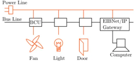
Figure 1: Scheme of an EIB installation
world’s only open standard for home and building control. This installation is visible to all the remote hosts, and con-sists in a power line and a bus line through which EIB com-mands are sent and device status is read. Devices are con-nected to the EIBus through Bus Coupling Units (BCUs) of various kinds, depending on the nature of the device (bi-nary for On/Off devices, analog for temperature control and sensors, ...). Accessing the EIBus using the IP protocol re-quires the special EIBNet/IP BCU. The bus can be config-ured through the proprietary ETS software from KNX or through the GPLed BCU SDK from the Automation Sys-tems Group of the Technische Universit¨at Wien4
. Fig. 1 shows an EIB installation.
2.2
Software
DANAH’s flexible software architecture clearly makes sep-aration between servers running on remote hosts, and clients running on users’ computers. As we wanted maximum reusabil-ity of clients and servers, these two components are the same respectively for any user and any remote host. Personal-ization of clients for some user is done through building user specific interfaces (which is beyond the scope of the DANAH system), and wheelchair automation is achieved through specific wheelchair drivers. The Fig. 2 depicts roughly the whole system architecture of DANAH.
To give even more flexibility, both clients and servers are built using a plugin based architecture. Communication pro-tocols (WiFi, Bluetooth, ...), automation control, wheelchair drivers and device runtimes (see 4.2) are loaded as plugins at startup, allowing easy tuning of servers and clients. System is then made extensible, since adding protocols or automa-tion technologies is just a matter of writing a library. The next sections describe the data models of DANAH. The dis-tribution process and the algorithmic parts are not part of this paper.
3.
ENVIRONMENTAL NAVIGATION
3.1
Background
Modelling is a key step in software development process. It consists of translating objectives, problems and system requirements to formal or semi-formal computerized forms called models, allowing automated manipulation. Depend-ing on the level of abstraction, models can reflect a sys-tem’s global architecture as well as its detailed internal data structures and execution flow. In DANAH, we use UML5
, 4 https://www.auto.tuwien.ac.at/~mkoegler/index. php/bcus 5 http://www.uml.org
Figure 2: Scheme of the system architecture and HW/SW mapping
the standardized specification language for software model-ing that includes a graphical notation for system description. Building a model for environmental navigation allows DANAH to have the necessary knowledge about lifespace, with re-gards to system requirements (large scale structures and distribution of information). Various models have been pro-posed in many studies most of them fall into two major categories : metrical representations where the lifespace is described by means of distances and angles, and topological representations in which the lifespace is discretized into ac-cessible areas connected together. Both representations are used depending on several criteria such the way the data is collected or the algorithms used.
3.2
Model
DANAH does not build its maps at runtime but rather loads them at startup, so the most suitable representation is topological. The topology is stored as a graph whose ac-cessible areas are mapped into nodes and connections into directed or undirected edges. Large graphs can cause perfor-mance problems because of great exploration time, and one solution is to use graph clustering [6]. It consists of grouping nodes to form super-nodes (or clusters) successively accord-ing to a similarity criteria to form a hierarchy called the hierarchical clustereg graph. An algorithm is applied to the whole hierarchy by using a descending approach. At the first iteration, it is run on the topmost graph, yielding (say for instance) a path. Then nodes of this path are expanded into their corresponding subgraphs for the next iteration. So instead of running the algorithm on the whole succes-sive graphs, it is run only on the subset returned by the expansion of the previous iteration, leading to speed im-provements. A drawback of using such a technique is that returned result is not optimal since the algorithm is not run on the base graph.
Thanks to information distribution, a two level hierarchical clustered graph is enough for DANAH. Each remote host has initially a topological representation of the lifespace it manages in a single cluster. During system execution, and with the help of a caching system, a remote host can import other host’s models. This model of clustering allows com-puting host paths at the first iteration, then node paths in the second one.
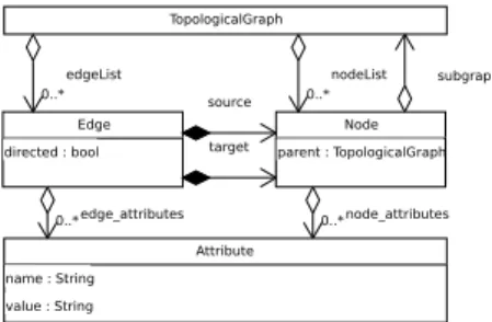
To improve navigation accuracy, this topological model is augmented with attributes stored in both nodes and edges. These attributes give additional information to complete the model. Attributes have a name and a value and can be or-ganized into groups of attributes. In DANAH, nodes contain
Figure 3: UML representation of our environmental model
the navigation group, in which the attributes x, y and ra-dius allow wheelchair localization in environment, and edges contain the length and width attributes that allow distance and path QoS evaluation. Fig. 3 gives the UML model of the environmental representation in DANAH. Its use is pre-sented in section VII.
4.
ENVIRONMENTAL CONTROL
4.1
Background
Additionally to the environmental knowledge, a model for device and service representation is needed. Moreover, as DANAH allows not only controlling single devices but also provides means of automation involving several devices, the underlying environmental control model must offer enough expressivity to describe both devices and complex activation sequences.
Individual activation of devices may become tricky espe-cially when they are repetitive. For instance, leaving a user’s room involves switching off the lights and the TV, and open-ing the door. Without the help of an assistive system, each action has to be performed individually requiring the user to move. DANAH offers the user to act on devices from its place using some presentation interface, for instance a GUI. But even if moving is no longer required, the user still has to individually perform actions, thus choosing first the device to control, and then the action to perform on it. For the disabled, this can be a serious concern, as some users are not capable of accurate enough clicks or selection. Repet-itive and frequently performed actions should be gathered into one single action and presented to the user. Scenarios aim to provide a mean of automation for repetitive actions by allowing the activation of actions from various devices in some order. In the following, we present first the device model, then the concept of scenario and its modeling.
4.2
Model
From DANAH’s view, controllable devices are called re-sources because each one can be used by a limited num-ber of users at once. The resource model includes a user friendly name and a list of of provided functions called op-erations which may success or fail during execution, a list of running modes and a list of states. Modes express the ability of a resource to have different running schemes, for instance, doors can have a normal and an emergency running modes. In a normal mode, the standard operations such as open and close are provided, while in emergency mode, the door is supposed to stay open and the user cannot act on
resource "3693" { name="Crepuscular switch" implementation="liblcrepsw.so.0" device { protocol="libeibd.so.0" uri="ip:localhost:6720" option "EIBAddr" { value="6/0/10" } } }
Figure 4: Resource description in DANAH.
Figure 5: UML representation of the resource model
it unless reset by the qualified staff. The resource model is associated to a physical device through a resource device model. Each device is accessible using some unique address, which can be either an IP address, a serial number, or a protocol specific address. Resource devices store the URI of the device and the communication protocol used to access them. Let’s take the example of a crepuscular switch. It can run in either Manual or Automatic modes and has the two states ON and OFF, its URI would be the IP address of the computer hosting the EIB daemon, which acts as a gateway between DANAH and the EIBus and its commu-nication protocol is the DANAH’s EIB protocol. To access the resource, protocols hold options in which various infor-mations can be stored, for instance the EIB address of the switch. Fig. 4 shows a description of a resource in DANAH. DANAH supports two kinds of resources. The first one presented above is called concrete resource and is mapped directly to a single controllable device using a dynamically loadable library (the implementation in Fig. 4, which stores the modes, states and behaviour of device). The other kind called composite resource can be seen as an aggregation of several resources, offering in its turn high-level operations. These resources are needed for automated activations. If we consider an operation exit room, its activation would require opening the door and turning off the lights. For that pur-pose, the composite resource room is built providing the two operations exit room and enter room. No physical devices are associated with the room, instead, the resource room can be seen as a virtual resource whose operations can be split into other resource operations. Therefore, each operation of a composite resource consist in an expression describing its relations with other resources’ operations. The Fig. 5 depicts the UML diagram of the resource model.
Expressions are written using predefined operators to com-pose operations, they can both express execution order and safety issues. For instance, to enter the room lights must be
switched on before closing the door, while to exit it lights have to be switched off only after closing the door. Regard-ing safety, it is important not to leave the room if open-ing the door fails, especially if the move is performed au-tonomously. For example, the AND-sequence executes op-erations sequentially, but stops as soon as one fails, and the composition itself fails. This enables giving more or less im-portance to operations with regards to their impact on user’s security. For instance, if switching on the lights fails, this has no serious consequences for user’s safety, while failing to open the door must stop the scenario. Using each operator’s semantic for execution and safety, one can compose complex scenarios. Furthermore, DANAH can suggest alternatives in case of failure. For example, when a door is blocked, a new path to reach the destination is computed. This process is called reconfiguration and improves availability of services. It is not deeply described in this paper.
5.
LINKING THE TWO MODELS
5.1
Resources with activation nodes
As seen above, DANAH splits its data into environmen-tal navigation model and environmenenvironmen-tal control model, em-phasing separation of roles in a two layer architecture. How-ever, the core system uses informations from both models to perform navigation and environmental control. To be able to aggregate data from the models, there exist links between them. For resources, we can distinguish two kinds with re-gards to their link with the environment model, and this is motivated by the fact that some resources must be activated at specific positions, while others can be activated from any-where. We call the first kind resources with local activation and the second one resources with distant activation. Exam-ple of a local activation resource is the lift, which requires the user to be nearby, whereas lights can be activated from any-where in the room. Therefore local activation resources are linked to the environment through activation nodes, which are nodes of the environmental navigation model.
5.2
Environment triggering functions
Let us consider a local activation resource on which the user wishes to perform an operation. DANAH starts by finding a path to reach one of its (indistinguishable) activa-tion nodes, then sends commands to move the wheelchair. During the move, it may be necessary to perform some envi-ronmental control, such as opening or closing intermediate doors and using elevators, therefore the environment must trigger functions. In DANAH, information about environ-mental control while in navigation is described using edges’ attributes [7]. Edges contain an entry, course and exit at-tributes, which will respectively trigger functions when en-tering, crossing and exiting an edge. For instance, the edge linking the nodes from both sides of a door will have and entry and an exit corresponding to opening and closing the door. Fig. 6 gives an example of environment triggering functions.
6.
DEVELOPER’S VIEW
In this section, we present DANAH from a developer’s perspective. When it comes to building the data needed by DANAH, the starting point is the building topology. Most
Figure 6: Navigation triggering environmental con-trol
of the time, computerized data of buildings are not available, thus the developer has to deal with blueprints in order to get by some means a computerized version. This is the most difficult task as it is hard, time consuming and error prone, especially when it comes to build precise representations in terms of distances and scale. To solve such a problem, auto-mated methods exist giving more or less accurate results [8]. They rely on scanned maps to generate topologies. The main drawback is that maps contain more information than needed for topology generation and thus automatic inter-pretation may fail or produce erroneous results because of detail misinterpretation, such as texts. To improve result accuracy, the maps are manually preprocessed or annotated before automatic topology generation process is being ap-plied.
In DANAH, we have defined a methodology and a set of tools in order to automatically generate the necessary data, including maps, resources, links and expressions, with the help of a general purpose object-oriented vector drawing ap-plication that supports layers. The idea is to put each part of the system model into a layer and then generate appro-priate data using an automated process. Staring from the lowest layer which contains a scanned map of the environ-ment, the layer GRAPH is added and the the topology is drawn in a flat form. Advantages of this technique are exact mapping between topology and reality and conservation of distances, scale and automatic update of objects’ positions and lengths. Remote hosts are added in a new layer HOSTS and linked with the nodes of their topology. At this time, each remote host is supposed to own only one cluster and there is a one-to-one mapping between a remote host and its unique cluster. Resources are added into another layer RE-SOURCES, attached to the hosts that manage them, then to their activation nodes using links. The topmost layer NAMES contains text objects attached to resources and re-mote hosts to specify names. Finally, the application must support the addition of some form of annotation for objects. These annotations are necessary to add non drawing related informations, such as resource addresses and operation ex-pressions. At the end, the drawing is saved and passed to the automatic generation tools.
DANAH uses the Inkscape6
vector drawing program which has the advantage to save its files into the SVG format, a specialization of the XML format. This format is easy to process due to the availability of a wide range of tools that use XML. The translation of a drawing into various data (directories, resource descriptions and topology files) in done using model transformations. The drawing orga-nized into layers can be seen as a presentation model from which descriptive models are obtained using model trans-formations. By model transformations we mean taking a 6
http://www.inkscape.org
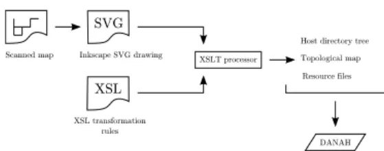
Figure 7: From presentation model to descriptive models
source formalism, apply transformations and get the target formalism. A model transformation is a set of transforma-tion rules written in a transformatransforma-tion language that can map source elements into target elements. As we intend to use XML as our source formalism, the XSLT (eXtendend Stylesheet Language Transform) processor is the appropri-ate tool. Transformations rules are stored in a set of XSL stylesheets and are passed to the XSLT processor along with the drawing. The result is one or several files in the target formalism, which can be XML or text. Fig. 7 depicts the transformation process. In DANAH, the result is a direc-tory per host, each one containing the topological map and the resources, along with some additional necessary data not described here.
7.
EXAMPLE
In this section we show the use of the two presented mod-els. Our goal is to build a DANAH system for use in a disabled person’s home equipped with a KNX/EIB installa-tion.
7.1
Methodology
A key step before going into system modeling is collect-ing specific user needs by ergotherapeutists. These needs are expessed in terms of scenarios used by the developer in the first step of system modeling. This step consists in interpreting scenarios and detemining the needed resources (concrete or composite), the appropriate topology and then performing placement of scenarios’s actions either in topol-ogy (for environmental triggers) or in resources’ operations. The second step is the system modeling itself as described above, using the developed prototyping tools. Finally, auto-matic generation process can be run to obtain the necessary data used during the execution of DANAH.
7.2
Study user needs
Ergotherapeutists provided us with the following scenario used when the person arrives at home :
Action On failure do Stop
1 Open portal Emergency call yes 2 Exterior lignts on
3 Alarm off Emergency call yes 4 Open door Emergency call yes 5 Open stores
6 Close portal 7 Exterior lights off
8 Adjust temperature Emergency call 9 Interior lights on Emergency call 10 Close door Emergency call 11 Turn on computer
• Determine resources : according to the scenario, the concrete resources Portal, Alarm, ExtLights, IntLights, Door, Computer and Emergency are needed. For tem-perature, a composite resource Heaters is added and linked with all the available concrete resources Heater. Same for the Stores composite resource. Regarding the scenario itself, it can be considerd as an operation of the composite resource Home.
• Determine topology and placement : it consists in find-ing in the scenario actions that may be part of envi-ronment triggers. Here it is the case of actions 1, 4 and 10. For the door, there must be an edge that trig-gers the action open before entering and another that triggers the action close after. This edge will trigger the approriate actions when crossed (using the entry, course, exit attributes). Therefore, these actions will not be part of the final operation Home.Enter, but rather actions triggered by the environment itself, in-dependently from any scenario. In addition, actions on lights should also be set inside environment triggers in-stead of scenario. Therefore, crossing the edge of the door will open the door and turn on interior lights in its entry attribute, and close the door and turn off ex-terior lights in its exit attribute. According to the sce-nario, some actions require further processing in case of failure, and some of them stop the scenario. This is handled by the operators of the environmental control model : the ORSEQ operator allows to run corrective ac-tions before continuing the scenario, while the EXCEP operator runs the corrective action, but stops the sce-nario.
• Build model and perform automatic generation : af-ter these two steps, the developer is now ready to use the rapid prototyping tools. It scans the house’s map, draws the obtained topology, sets the resources and the environment triggers in the layered drawing. This drawing is then passed to the transformation tools to get one directory per host with the necessary data (topology, resources, ...). DANAH uses these infor-mations to deliver the services to the user.
8.
CONCLUSION
In this paper we described the underlying models of the DANAH assistive system. Navigational knowledge is used to compute appropriate paths and deliver the right commands to the wheelchairs, while control knowledge is used to act on automated devices. Combining the two models allows DANAH to deliver services in a fully automated manner, including wheelchair navigation and induced device activa-tions. From a user’s perspective, effort is considerably re-duced as it has to only select the final desired service. From a developer’s perspective, easy and intuitive methods and tools for rapid prototyping have been presented to cut de-velopment time and costs, which is a step towards adoption of ATS. We are currently working on improving the recon-figuration process, which is useful in case of device failures or obstacles in path.
9.
REFERENCES
[1] Contribution of France. Les changements de la structure par ˆage de la population et leurs
Figure 8: Our example in Inkscape drawing program
cons´equences sur le d´eveloppement. In UN Commision on Population and Development, 40th session. April 9-13, 2007. New-York.
[2] T. R¨ofer and A. Lankenau. Architecture and applications of the Bremen Autonomous Wheelchair In Information Sciences Journal. Vol 126, 2000. [3] J.-H. Do, H. Jang, S. H. Jung, J. Jung and Z. Bien.
Soft Remote Control System in the Intelligent Sweet Home. In IEEE International Conference on Intelligent Robots and Systems. 2005
[4] St. Carruthers, A. Humphreys and J. Sandhu. The market for R.T in Europe : A Demographic Study of Need. In Proceedings of the 1st TIDE Congress (Technology for the socio-economic Integration of Disabled and Elderly people). Amsterdam, 1993. [5] A. Brandt, B. Seelen and Z. Biilmann. Why don’t
hospitals use electronic communication aids for patients who are severely motor impaired and who can’t speak ?. In Proceedings of the Second European Conference on the Advancement of Rehabilitation Technology. Stockholm, 1993.
[6] P. Berkhin. Survey of clustering data mining
techniques. In Technical report, Accrue Software. San Jose, CA. 2002.
[7] B. Krieg-Br¨uckner, U. Frese, K. L¨uttich, C. Mandel, T. Mossakowski and R. Ross. Specification of an Ontology for Route Graphs. In Proceedings of the International Conference on Spatial Cognition. October 2004. Germany.
[8] C. Gold. Simple Topology Generation from Scanned Maps. In Proceedings of the Computer Assisted Cartography, AUTOCARTO 13, ACM/ASPRS. Seattle, 1997.
[9] L. Jiang, D. Liu and B. Yang. Smart Home Research. In Proceedings of the IEEE International Conference on Machine Learning and Cybernetics. 2004.
[10] V. Ricquebourg, D. Menga, D. Durand, B. Marhic, L. Delahoche and C. Loge. The Smart Home Concept : our immediate future. In Proceedings of the 1st IEEE International Conference on E-Learning in Industrial