UNIVERSITÉ DE MONTRÉAL
FIRST SIMULINK BENCHMARK FOR OFF-LINE AND REAL-TIME
SIMULATION OF MORE-ELECTRIC AIRCRAFT (MEA) ELECTRICAL
POWER SYSTEM
LEONARDO MONTEALEGRE LOBO DÉPARTEMENT DE GÉNIE ÉLECTRIQUE ÉCOLE POLYTECHNIQUE DE MONTRÉAL
MÉMOIRE PRÉSENTÉ EN VUE DE L’OBTENTION DU DIPLÔME DE MAÎTRISE ÈS SCIENCES APPLIQUÉES
(GÉNIE ÉLECTRIQUE) Août 2011
UNIVERSITÉ DE MONTRÉAL
ÉCOLE POLYTECHNIQUE DE MONTRÉAL
Ce mémoire intitulé:
FIRST SIMULINK BENCHMARK FOR OFF-LINE AND REAL-TIME SIMULATION OF MORE-ELECTRIC AIRCRAFT (MEA) ELECTRICAL POWER SYSTEM
présenté par : MONTEALEGRE LOBO Leonardo
en vue de l’obtention du diplôme de : Maîtrise ès sciences appliquées a été dûment accepté par le jury d’examen constitué de :
M. KOCAR, Ilhan, Ph.D., président
M.SIROIS Frédéric, Ph.D., membre et directeur de recherche
M.MAHSEREDJIAN Jean, Ph.D., membre et codirecteur de recherche M.DUFOUR Christian, Ph.D., membre
DEDICATION
In loving memory of my grandmother Carmen, whose flame extinguished shortly after I started this program, but her memory kept me warm during this amazing ride. Para vos abuelita!
ACKNOWLEDGEMENTS
I would like to thank my lovely Elani, for her support, her presence and her soft and calming words in the most challenging moments of this project. To my family, from whom, despite the distance, I felt the support and encouragement that allowed me to keep me going until the end. To my friends, the ones I made here and allowed me to travel through their amazing stories and the ones I left back home. The support during this process was remarkable.
I would like to thank the Instituto Costarricense de Electricidad for the chance to pursue this master's degree, one of the most rewarding experiences of my life.
I would be always grateful to Professor Frédéric Sirois for opening me the door to this wonderful institution and to Professor Jean Mahseredjian for selecting me to participate in this project. For their support, knowledge and understanding, I will be forever indebted.
Last but not least, I would also like to thank my co-workers, especially Marc-André Lemaire, for their help and support throughout the project, Mr. Claude Lavoie from Bombardier, and Mr. Luc-André Grégoire from Opal-RT for his invaluable contribution in work on the real-time simulation.
This research is supported and funded by Bombardier Aerospace, Pratt & Whitney Canada, Opal-RT Technologies and by the Consortium for Research and Innovation in Aerospace in Quebec (CRIAQ).
RÉSUMÉ
Le concept des avions plus-électrique est une nouvelle cible technologique pour les fabricants d'avions. Il concerne la réduction du poids de l'avion, de la consommation de carburant et l'amélioration de l'efficacité de l'énergie. Tous ces éléments constituent des avantages potentiels importants.
Les avions conventionnels utilisent les puissances hydraulique, mécanique, pneumatique et électrique en tant que sources d’énergie. Pour augmenter l’efficacité de ces systèmes, des études sont effectuées dans le but d’augmenter la part d’énergie électrique utilisée dans les avions pour la génération, la distribution et l’utilisation de la puissance électrique. Parallèle à l'augmentation de l'efficacité, le nombre et la qualité des études techniques relatives aux étapes de conception, design et essais de validation, doivent aussi être augmentés et/ou améliorées. Les modèles mathématiques et les outils de simulation constituent des moyens efficaces permettant de prédire le comportement du réseau électrique, corriger des erreurs de design, éliminer certaines étapes de prototypage et réduire le temps d’essai des composantes. Les outils de simulations peuvent augmenter la robustesse des systèmes tout en réduisant les essais dispendieux au sol et en vol. De plus, les outils de simulation offrent une infinité d’options pour l’étude d’un grand nombre de scénarios d'opération et pour l'optimisation. Les outils de simulation modernes deviennent de plus en plus sophistiqués et permettent, si les données sont disponibles, de créer des modèles très près de la réalité autant pour les composants que pour les systèmes. La simulation en temps réel permet de faire des essais sur des équipements réels (« hardware-in-the-loop ») pour valider des modèles et déterminer des paramètres.
Ce mémoire de maîtrise présente un premier test de simulation et d’analyse pour le réseau électrique du Global Express de Bombardier. Les simulations sont effectuées en temps différé et en temps réel. Les outils utilisés sont Simulink pour la simulation en temps différé et le simulateur OPAL-RT basé sur Simulink pour la simulation en temps réel. Cette recherche sert à définir les goulots de modélisation ainsi que les besoins au niveau des données nécessaires à la modélisation. Ce mémoire établit aussi les besoins de validation et de mesure pour la modélisation d'un avion plus électrique. La simulation en temps réel est particulièrement contraignante et ce mémoire a permis de tester une nouvelle méthode de résolution en temps réel.
ABSTRACT
Conventional aircrafts use hydraulic, mechanical, pneumatic and electrical energy sources to supply their systems. In order to increase the efficiency of such systems, it is needed to increase the penetration level of electrical systems and components in aircrafts for generating, distributing and utilizing electrical power. An important step is to develop numerical models for studies related to the conception, design and testing stages. Mathematical modeling and simulation tools constitute an efficient approach for predicting operational behaviour, correcting design errors, eliminating prototyping steps and reducing component and overall testing cycles. Simulation tools can increase system robustness while reducing expensive ground and flight tests on the actual aircraft. Moreover, simulation tools offer limitless options for studying huge numbers of operational scenarios and detecting failure conditions. Modern simulation tools for electrical circuits and systems have become very sophisticated and, if data is available, can be used to create extremely precise models for components and complete systems. Real-time simulation tools allow testing actual physical components (hardware-in-the-loop) and can be used to validate models and derive model parameters.
This research presents an initial benchmark for the simulation and analysis of the Bombardier Global Express aircraft electrical power system. Both for off-line and real-time simulations are considered. The considered tools are Simulink for off-line simulations and the Opal-RT simulator (based on Simulink) for real-time simulations. These tools allow achieving advanced models and testing the aircraft system in a high scope of scenarios. The research identifies modeling bottlenecks and data needs, establishes validation needs and proposes measurement tests for qualifying component models. It is established that the real-time simulation of the developed power system is particularly complex. An available and new real-time simulation method is tested at the end and demonstrates the need for further research.
TABLE OF CONTENTS
DEDICATION ... III ACKNOWLEDGEMENTS ... IV RÉSUMÉ ... V ABSTRACT ... VI TABLE OF CONTENTS ...VII LIST OF TABLES ... X LIST OF FIGURES ... XI LIST OF ABREVIATIONS ... XV LIST OF ANNEXES ... XVII
INTRODUCTION ... 1
CHAPITRE 1 GLOBAL EXPRESS FUNDAMENTALS ... 8
1.1 Global Express Description ... 8
1.2 Electrical Power System Characteristics ... 8
1.2.1 Primary AC Generation System ... 10
1.2.2 Auxiliary AC Power ... 13
1.2.3 AC Electrical Power Distribution ... 14
1.2.4 External AC System ... 21
1.2.5 Emergency AC Power Generation System ... 21
1.2.6 DC Electrical System ... 22
1.2.7 Battery System ... 25
1.2.8 External DC System ... 25
CHAPITRE 2 GLOBAL EXPRESS AIRCRAFT ELECTRIC POWER SYSTEM MODEL . 28 2.1 Operating Conditions ... 28
2.2 AC Electrical System ... 29
2.2.1 Variable Frequency Generators Model ... 31
2.2.2 AC Power Centre (ACPC) ... 33
2.2.3 AC Switching Control Centre (ACSCC) ... 38
2.2.4 AC Cables ... 42
2.2.5 AC Loads ... 49
2.2.6 Transformer Rectifier Unit (TRU) ... 52
2.3 DC Electrical System ... 56
2.3.1 DC Cables ... 56
2.3.2 DC Loads ... 60
CHAPITRE 3 GLOBAL EXPRESS AIRCRAFT ELECTRIC POWER SYSTEM SIMULATION AND ANALYSIS ... 62
3.1 Voltage Frequency Generators (VFGs) and phase sequence ... 64
3.2 AC Busses ... 69
3.3 Electric Hydraulic Pump (EHP) ... 72
3.4 Transformer Rectifier Unit (TRU) ... 75
3.5 DC Busses ... 78
3.6 Switching Time Delay ... 81
3.7 Case Study 1: VFG4 fails at 200 ms and restores operation at 300 ms ... 83
3.8 Case Study 2: VFG1 and VFG4 fail at 200 ms and restores operation at 300 ms ... 88
3.9 Case Study 3: VFG1 phase A, VFG4 phase B and phase C fail at 200 ms while VFG4 phase A, VFG1 phase B and phase C remind connected ... 91
CHAPITRE 4 GLOBAL EXPRESS AIRCRAFT ELECTRIC POWER SYSTEM IN A REAL-TIME ENVIRONMENT ... 94
4.2 From Simulink to Real-Time: Global Express Electric Power System Real-Time Modeling ... 95 4.2.1 SM_Master Subsystem ... 98 4.2.2 SS_ACSCC Subsystem ... 107 4.2.3 SS_DCSCC Subsystem ... 108 4.2.4 SS_BUS1 Subsystem ... 109 4.2.5 SS_BUS2 Subsystem ... 110 4.2.6 SS_BUS3 Subsystem ... 111 4.2.7 SS_BUS4 Subsystem ... 112 4.2.8 SS_DCBackup Subsystem ... 113 4.2.9 SS_Console Subsystem ... 114
4.3 Testing the Real-Time Model ... 117
CONCLUSION ... 125
REFERENCES ... 127
LIST OF TABLES
Table 1.1. Operating parameters for APU control unit [18] ... 13
Table 1.2. Auxiliary AC Power management according different conditions [18] ... 14
Table 1.3. Power sources from the ACPC to the CCBP configuration [18] ... 19
Table 1.4. Bus power source logic [18] ... 20
Table 1.5. TRU feeding configuration [18] ... 24
Table 2.1. Operating Conditions [19] ... 28
Table 2.2. Parameters for Three-Phase Programmable Voltage Sources ... 31
Table 2.3. AC system contactor operation logic with APU available [19] ... 34
Table 2.4. Positive and Negative Sequence Impedance for 400 Hz at 20°C [21] ... 44
Table 2.5. Zero Sequence Resistance assuming a perfect ground plane at 20°C and 400 Hz [21] 46 Table 2.6. AC Cable length estimation ... 48
Table 2.7. Self impedance values for AC Cables in the aircraft electric power system ... 48
Table 2.8. Assumption during EHP's modeling ... 51
Table 2.9. Parameters for Asynchronous Machine block ... 52
Table 2.10. Parameters of the Universal Bridge ... 55
Table 2.11. Parameters for Three-Phase Transformer (Two Windings) Block ... 55
Table 2.12. DC resistance value for 20°C [21] ... 57
Table 2.13. DC Cable length estimation ... 58
Table 3.1. Comparison between theoretical and simulated values from DC busses ... 79
LIST OF FIGURES
Figure 1.1. Electrical power system [18] ... 9
Figure 1.2. Variable Frequency Generator [18] ... 10
Figure 1.3. Variable Frequency Generator Block Diagram [18] ... 11
Figure 1.4. Generator Line Contactors [18] ... 12
Figure 1.5. Auxiliary Power Unit (APU) Generator [18] ... 13
Figure 1.6.AC Electrical Power Distribution [18] ... 15
Figure 1.7. ACPC functional block [18] ... 16
Figure 1.8. Cockpit Circuit Breaker Panel (CCBP) Electrical Schematic [18] ... 18
Figure 1.9. AC External Power [18] ... 21
Figure 1.10. AC Emergency Electrical System Power Control and Monitoring [18] ... 22
Figure 1.11. DC Electrical Power Generation and Distribution System [18] ... 23
Figure 1.12. DC Electrical Power [18] ... 24
Figure 1.13. External DC Power Schematic [18] ... 26
Figure 1.14. Electrical System Schematic [18] ... 27
Figure 2.1. One-line diagram of aircraft electric power system ... 30
Figure 2.2. VGF's block implemented in Simulink and its location in actual aircraft electric power system ... 32
Figure 2.3. ACPC Electrical System schematic [19] ... 33
Figure 2.4.ACPC implementation in Simulink ... 35
Figure 2.5. Maximum switching time implemented in Simulink ... 36
Figure 2.6. Phase sequence of Generator 2 and 3 implemented in Simulink ... 37
Figure 2.7. Flowchart of the ACSSC logic switching signal command ... 38
Figure 2.9. "Measurements" subsystem architecture of signal processing (second part) ... 40
Figure 2.10. Schematic of the ACSCC implemented in Simulink (first part) ... 41
Figure 2.11. Schematic of the ACSCC implemented in Simulink (second part) ... 42
Figure 2.12. Cross-section of a nickel coated copper cable linking AC BUS 1 to AC BUS 1A [19] ... 43
Figure 2.13. AC Cable Block implementation in Simulink ... 43
Figure 2.14. Zero sequence Impedance for one laced group at 400 Hz [21]. ... 46
Figure 2.15. Initialization commands for the AC cable block ... 47
Figure 2.16. Location of the AC loads in the Global Express one-line diagram ... 49
Figure 2.17. AC Unbalanced Load implementation in Simulink ... 50
Figure 2.18. EHP implementation in Simulink ... 51
Figure 2.19. Schematic diagram of a typical TRU [23] ... 53
Figure 2.20. Location of the TRUs within the Global Express one-line diagram ... 54
Figure 2.21. TRU model in Simulink ... 56
Figure 2.22. Cross-section of a tin coated copper cable used for linking ESS TRU and DC ESS BUS [19] ... 56
Figure 2.23. DC Cable Block implemented in Simulink ... 57
Figure 2.24. Initialization commands for the DC cable block ... 59
Figure 2.25. DCSCC implemented in Simulink ... 61
Figure 3.1. Complete aircraft electric system implementation in Simulink (first part) ... 62
Figure 3.2. Complete aircraft electric system implementation in Simulink (second part) ... 63
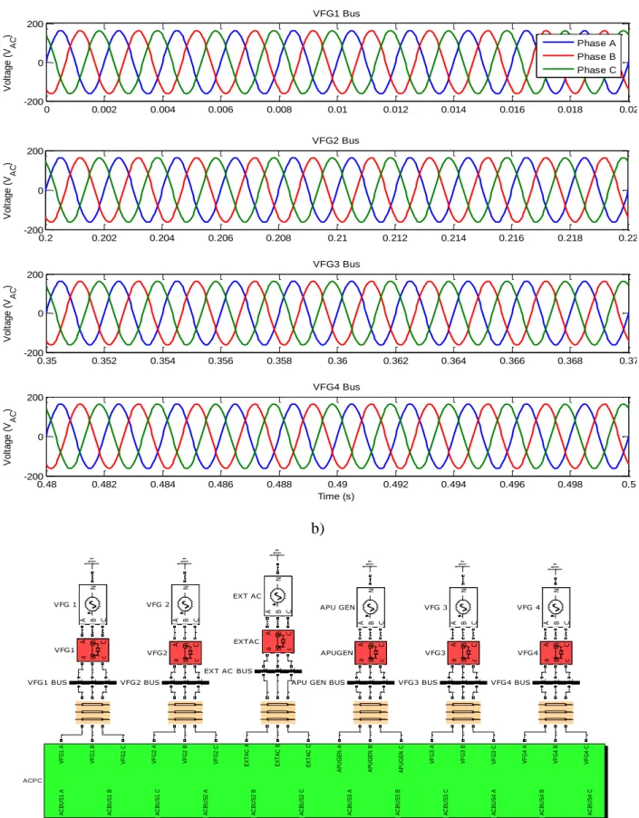
Figure 3.3. a) Voltage simulation results from VFG busses and b) VGF busses location ... 65
Figure 3.4. Current simulation results from VFG busses ... 66
Figure 3.5. FFT analysis of current simulation results from VFG busses ... 67
Figure 3.7. a) Voltage simulation results from AC busses and b) Busses location ... 70
Figure 3.8. Current simulation results from AC busses ... 71
Figure 3.9. FFT analysis of current simulation results from VFG busses ... 72
Figure 3.10. Voltage and current measurements between Simulink model and available data ... 73
Figure 3.11. EHP comparison between Simulink and EMTP-RV ... 74
Figure 3.12. Waveforms of the EHP current's start-up ... 75
Figure 3.13. a) TRU steady-state voltage behaviour and b) TRUs location ... 76
Figure 3.14. TRU voltage ripple ... 77
Figure 3.15. TRU voltage transient behaviour during VFG4 failure ... 78
Figure 3.16. a) DC voltage and current steady-state simulation results and b) DC busses location ... 80
Figure 3.17. Effects of changing the switching time delay on the DC ESS bus voltage ... 81
Figure 3.18. Effects of changing the switching time delay on the VFG1 bus RMS voltage ... 82
Figure 3.19. VFGs supplying AC busses in case study 1 ... 83
Figure 3.20. Current simulation results from VFG busses when VFG4 fails at 200 ms ... 84
Figure 3.21. VFG1 Bus current waveforms from Simulink and EMTP-RV ... 85
Figure 3.22. DC voltages when VFG4 fails ... 86
Figure 3.23. BATT Bus voltage in Simulink and EMTP-RV during VFG4 failure ... 87
Figure 3.24. VFGs supplying AC busses in case study 2 ... 88
Figure 3.25. Current simulation results from VFG busses when VFG1 and VFG4 fail at 200 ms 89 Figure 3.26. Zoom in to the current simulation results from VFG busses ... 90
Figure 3.27. DC voltage simulation results when VFG1 and VFG4 fails at 200 ms ... 91
Figure 3.28. Zoom in to the current simulation results from VFG busses in case study 3 ... 92
Figure 3.29. DC voltages simulation results when a malfunction occurs while switching ... 93 Figure 4.1. Separation of the Global Express electric power system for real-time environmental 96
Figure 4.2. Global Express aircraft electric power system for real-time simulation ... 97
Figure 4.3. SM_Master subsystem model for real-time simulation ... 99
Figure 4.4. OpComm implementation according to subsystem type ... 101
Figure 4.5. Effect of adding the memory blocks to real-time subsystem outputs ... 102
Figure 4.6. SSN Interface blocks implementation in Global Express electric power system real-time model ... 106
Figure 4.7. SS_ACSCC subsystem model for real-time simulation ... 108
Figure 4.8. SS_DCSCC subsystem model for real-time simulation ... 109
Figure 4.9. SS_BUS1 subsystem model for real-time simulation ... 110
Figure 4.10. SS_BUS2 subsystem model for real-time simulation... 111
Figure 4.11. SS_BUS3 subsystem model for real-time simulation... 112
Figure 4.12. SS_BUS4 subsystem model for real-time simulation... 113
Figure 4.13. SS_DCBackup subsystem model for real-time simulation... 114
Figure 4.14. SC_Console subsystem model for real-time simulation (first part) ... 115
Figure 4.15. SC_Console subsystem model for real-time simulation (second part) ... 116
Figure 4.16. Switching Signal Generator subsystem model for real-time simulation ... 117
Figure 4.17. DC ESS Bus voltage for different time steps using stub lines... 118
Figure 4.18. a) DC ESS Bus voltage for different time steps and b) DC ESS Bus for real-time and off-line simulations ... 119
Figure 4.19. VFG1 Bus phase A current for 1 μs and 70 μs ... 121
Figure 4.20. Zoom in to the current simulation results from VFG busses when VFG1 fails ... 122
LIST OF ABREVIATIONS
AC Alternating Current
ACPC Alternating Current Power Centre
ACSCC Alternating Current Switching Control Centre
Ah Ampere Hour
AM Asynchronous Machine
APU Auxiliary Power Unit BATT Battery
CAIMS Central Aircraft Information and Maintenance System CDU Control Display Unit
CMU Communications Management Unit
DC Direct Current
DCPC Direct Current Power Centre
DCSCC Direct Current Switching Control Centre ECS Environmental Control System
EHP Electro-hydraulic Pump
EICAS Engine Indication and Crew Alert System ELA Electrical Load Analysis
EMTP-RV Electromagnetic Transient Program, Revised Version
ESS Essential
ETC Emergency Tie Contactor ETFE Ethylene Tetrafluoroethylene
ETOPS Extended Range Operation with Two-Engine Airplanes EVS Enhanced Vision System
EW Electronic Warfare) EXT External
FADEC Full Authority Digital Engine Controller FCU Flight Control Unit
FMS Flight Management System GCU Generator Control Unit GLC Generator Line Contactor
ISA International Standard Atmosphere KEAS Knots Equivalent Air Speed kVA Kilovolt-amperes
LC Line Contactor
NiCd Nickel Cadmium
NM Nautical Mile
PF Power Factor
RAT Ram Air Turbine
SATCOM Satellite Communications SIGINT Signal Intelligence
SSPC Solid State Power Controller TRU Transformer Rectifier Unit
VA Volt-amperes
VF Variable Frequency
VFG Variable Frequency Generator Vrms Volts rms
LIST OF ANNEXES
INTRODUCTION
The more-electric concept is a new technological target for the aerospace manufacturers which involves reduction of fuel consumption, improvement of power efficiency and the eventual possibility of a significant reduction of aircraft weight, as some of the important potential benefits [1]. Conventional aircraft construction is based on hydraulic, mechanical, pneumatic and electrical energy sources. Therefore, in order to increase the efficiency of such systems, it is necessary to increase the penetration level of electrical systems and components in aircrafts for generating, distributing and utilizing electrical power. The goal of the all-electric aircraft concept is to eliminate as many hydraulic power sources and lines as possible, so that the more electric engine can be redesigned to produce thrust and more electrical power [2].
The more-electric aircraft (MEA) concept impacts significantly on aircraft electrical power system design, due to the fact that many functions conventionally managed by hydraulic, pneumatic and mechanical power are replaced by electric systems in order to reduce size and weight, and improve fuel efficiency [2]. This may result into a significant amount of power electronic converters and motor drive systems. Electrical power system design may evolve in many directions: AC, DC, hybrid, frequency-wild, variable voltage, together with the possibility of novel connectivity topologies, resulting in very large and perhaps impractical computing times when considering modeling and simulation [3].
In contrast, the increased usage of electrical power increases the power demands on the electrical system, placing new constraints on its dynamic performances and on power quality, so that new power system architectures must be designed, extensively analyzed, tested, validated and certified before implementation in an actual aircraft. Simulation tools must be used to support the more-electric concept.
Mathematical modeling and simulation tools constitute an efficient approach for predicting operational behaviour, correcting design errors, and optimizing the fabrication process [4]. Thereby, modeling of aircraft power systems is essential to study impacts on costs and electric architecture modifications. Furthermore, continuing developments in aircraft power systems lead to studies on power distribution systems at fixed frequency [5], [6] and variable frequency [4], as well as on power distribution at high DC voltage [7]. Despite all these studies, many approximations are made, either by necessity or by lack of data. Greater efforts must be invested
to study more precisely the stability of new distribution architectures, as the presence of power electronics on aircrafts is in constant growth. Other studies on power quality, transients and faults must be added to the long list of design steps in aircrafts [8], [9].
Sophisticated modeling and simulation tools considered in this research constitute an efficient methodology for predicting operational behaviour, extracting specific requirements and developing specific techniques for applications to the more-electric aircraft technologies, so that the expected models and simulation results would help to clarify complex problems, support the decision making and the technological deployments for the strategic design process. Furthermore, simulation tools can increase in accuracy, so that modeling could be made as realistic as possible with a great level of details and complexity.
There are off-line and real-time simulation tools. In off-line simulation tools, model accuracy usually takes precedence on the computational speed of the complete simulation. Real-time simulation tools offer the computational speed advantage and allow studying a very large number of operational scenarios within reduced time. In addition, such tools can provide real-time synchronized simulations and allow interfacing with external physical devices (hardware-in-the-loop). Such interfacing can be used to validate physical controllers, improve designs and even develop models through the analysis of black-box type physical device performance waveforms.. Both off-line and real-time simulation tools are part of this research.
Socio-economical context
Currently, the specifications for the aircrafts are more or less similar depending on the category: commercial, business or utility. An aircraft with the important technological breakthrough of the more-electric concept becomes more competitive in almost all of these operational specifications. An extensive list of expected benefits could be drawn for the more-electric concept over the conventional aircraft power systems. The most noticeable ones come from an envisioned conceptual and technical simplification of the systems [5].
Reduction of: components count, empty weight, systems and components volume, life-cycle costs, design effort, fuel consumption.
Improvement of: operational range, systems and engine efficiency, reliability, maintainability, safety, power density, system flexibility.
Based on a literature overview, remarkable initiatives have been developed in US and Europe to design more-electric aircrafts. Airplane manufacturers, such as Airbus and Boeing, have already applied new concepts of electric actuation within their last state-of-the-art development programs for Boeing 787 [10] and Airbus A380 [11]. Many manufacturers put their hopes in the increase of electric power usage as the solution for reducing fuel consumption and emissions levels.
To accelerate the development of more-electric aircrafts, it is important to establish a tight collaboration between the participating manufacturers and the universities as it has been done during this research, which is, with the help of manufacturers, a powerful innovation path that can quickly result into practical developments and implementations.
According to available economical analysis (see [12]), global commercial aviation electrical power systems and infrastructure market is estimated to reach $24 billion by 2017. Furthermore, more-electric aircraft architectures attempt to offer lower recurring costs, require less parts, reduce fuel consumption, improve operational performance, reduce maintenance and reduce the cost of operation.
Technical context
In a technical context, modern research and advancements in aircraft systems are in the fields of flight control, power generation and power control, and engine control [6]. In addition, there are substantial benefits in weight reduction when replacing hydraulic circuits by more-electric flight controls. Other benefits are in maintenance and reliability.
To present a global picture, the conventional aircraft hydraulic systems include primary and secondary flight controls, landing gear and utility actuation. In the past, electrical machines did not provide sufficient power density to drive these loads. Recent developments in induction, switched reluctance and permanent magnet motors provide new design options. Moreover, the use of hydraulic fluid is hazardous since it could leak. By using electrically-driven pumps or even eliminating all hydraulic components, mechanical simplicity and increased reliability can be achieved.
The increased number of electrical applications in aircrafts increases the demands on the aircraft electrical power generation and distribution system. Traditional aircrafts are based on the constant frequency generator concept, which requires extra equipment to cancel speed variations
within the generator. Such equipments can be eliminated through variable frequency generators. The Bombardier’s Global Express jet is already using a variable frequency system.
In a conventional aircraft, electrical power generation is done by externally engine-driven generators. The electrical machines are connected to the engine via shafts and gearboxes. The goal of the more-electric approach is to integrate them into the core of the engine.
An important aspect is power generation during emergency situations. New developments in fuel cells and fan-driven generators allow replacing the currently used ram air turbine (RAT) technology, increasing reliability, and offering supplemental power options. The feasibility of the more-electric concept relies on the development of lightweight and fault tolerant power distribution architectures. There are many design options. The primary electrical power includes generation and distribution to the main busses and primary loads. The electrical sources on an aircraft are the main generators, Auxiliary Power Unit (APU), Ram Air Turbine (RAT), battery and external power.
This system could be constant frequency AC (3Φ/115 VAC/ 400 Hz), variable frequency AC (324 Hz to 720 Hz), high-voltage DC (270 V DC or 350 V DC) and even multiphase (5Φ, 7Φ). Also, these main power levels need conditioning and conversion in order to feed different loads inside the aircraft, such as the 28 V DC avionic busses. This is referred to the secondary electrical power system. The conversion can be achieved on the basis of different converter topologies.
In the power generation and engine control aspects, the more-electric engine (MEE) plays a key role in the more-electric design of aircrafts [2]. The engine itself includes electric loads, such as electric fuel and oil pumps, active magnetic bearings and electrically actuated engine guide vanes. Complicated hydro-mechanical controls are replaced by digital electronics controls (see FADEC: full authority digital electronic engine control) [13]. The MEE incorporates smart fuel valves, fuel pumps and distributed control technologies for simplification of control system architectures. The elimination of hydraulic, mechanic and pneumatic functions in the MEE is for concentrating on the production of thrust and electrical power [13].
It is apparent that advanced aircraft power system architectures may include various levels of sophistication. Such architectures are based on bi-directional, DC/DC, AC/DC and DC/AC power converters [8]. The term Multi-converter Power Systems is used to designate such systems with solid state switching power converters [8]. In addition, it is required to study and coordinate
protection systems, so modeling and simulation is essential for the design, development and operational reliability of more-electric aircrafts.
Two types of tools can be used for the simulation and analysis of aircraft power systems: off-line and real-time. On both cases the simulation methodology encompasses electromagnetic transients. Steady-state initial conditions can be established using phasor domain analysis.
Off-line tools offer the advantages of high modeling precision since such tools do not need to compromise for synchronized real-time interfacing with external physical devices. There are no time-step and network size constraints in line programs. The limitation is that currently off-line simulation tools cannot be directly interfaced with external controllers.
Real-time simulators can be applied for studying a very large number of operational scenarios within reduced time and for interfacing with external physical devices. Such interfacing is essential for validating and improving controllers and validating mathematical models.
This project includes the development of specific models, such as power converters, AC and DC cables, AC and DC loads, switching controls and rotating machines. The modeling may become dependent on the simulation type and on the required precision for the studied electrical frequencies. A complete aircraft power system is developed and presented.
The development of benchmarks for aircrafts and the setup of advanced testing facilities contribute to the study of various aircraft power system architectures and testing their performance within economical, stability and reliability constraints.
This thesis is divided as follows: Chapter 1: Global Express Aircraft Electric Power System Fundamentals, Chapter 2: Global Express Aircraft Electric Power System Model, Chapter 3: Global Express Aircraft Electric Power System Simulation and Analysis and Chapter 4: Global Express Aircraft Electric Power System simulation in a Real-Time Environment.
Main Objective
The goal of the project is to develop and validate a first real-time bechmark in Matlab/Simulink [14] for the simulation, analysis and evaluation of more-electric aircrafts, electrical power system architectures based on the Bombardier's Global Express aircraft electric power system. The setup in Simulink allows both off-line and real-time simulations. Real-time simulations are performed using the Opal-RT system [15].
Specific Objectives
In order to achieve the main objective of the investigation, three specific objectives were established:
1. Develop the MATLAB/Simulink off-line model for Bombardier's Global Express aircraft electric power system.
2. Validate results using a specialized software for the simulation and analysis of transients in power systems named EMTP-RV (Electromagnetic Transient Program, Revised Version [16]), as well as real aircraft electric measurements.
3. Convert the MATLAB/Simulink off-line model for Bombardier's Global Express aircraft power system into real-time using Opal-RT environment (based on Simulink) [15].
Methodology
The research is divided into the following steps:
1. Literature Review and Industrial Meetings with Bombardier for data gathering and acquiring knowledge on the system to be simulated.
2. Model development and assemblage of complete electrical network. 3. Simulations and analysis of results and data Processing.
4. Validation with EMTP-RV and measurements.
5. Simulation in real-time of the Global Express Aircraft Electric Power System.
Literature review and industrial meetings
The literature review shows the way research programs in more-electric aircrafts have been conducted in the past 20 years, providing a fundamental starting point for the research. Topic issues as the general concept of MEA ( [1], [2], and [3] ), its expected benefits and objectives, in addition to simulation methodologies and strategies ( [6], [17] ) and complex problems related to stability assessment of power electronics were studied and analyzed during this stage.
Meetings with the industrial partners are to provide: co-supervision, data on the simulated aircraft systems, available measurements and test data, problematic operational cases and guidance on applicable standards and internal certification methods.
In the model development stage, the first task is to tackle the computational efficiency of the model. The second task addresses the precision of the model. Each time a new improvement or network component is introduced into the benchmark it is needed to validate efficiency, accuracy and stability of the model. In addition, each model is simulated as isolated from the aircraft electric power system and then incorporated in the entire power system model for increasing the accuracy of the simulations.
Once the off-line benchmark achieves the desired objectives, it is converted into real-time using the Opal-RT real-time simulator. The Opal-RT simulator is based on MATLAB/Simulink which offers an advanced open-architecture and allows reconfigurations as needed [8]. In addition, there is a Simulink interface with EMTP-RV for large scale system simulations [15].
Validation and improvement of the real-time Global Express aircraft power system model
Each new improvement is tested sequentially in order to compare the performance of the model with and without the improvement, allowing an immediate feedback and the correction of possible problems or errors. The obtained model is implemented into the real-time platform of Opal-RT Technologies Inc. and some case studies are run in this simulator.
CHAPITRE 1
GLOBAL EXPRESS FUNDAMENTALS
This chapter specifies the electrical characteristics for the Global Express Aircraft Electrical Power System. It attempts to summarize the main lines found in technical manuals related to aircraft electrical architectures, specially the so called “Aircraft Type Course Technical Training Guide: ATA 100 Breakdown” [18].
1.1 Global Express Description
The Global Express is a luxury business jet aircraft for medium and long range mission and multi-role applications such as flight inspection, search and rescue, SIGINT (Signal Intelligence), EW (Electronic Warfare) and 30 passenger transporters. The aircraft is powered by BMW/Rolls Royce engine BR710 and it is designed to meet the intent of the Extended Range Operation with Two-Engine Airplanes (ETOPS) requirements, with 180 minutes diversion time. In addition, the aircraft is designed to be self-sufficient and have the capability to operate without limitation or restriction at a 13000 ft elevation airport, as well as safely cruise at 51000 ft [19].
The aircraft has a 41000 ft minimum initial cruise altitude at ISA + 10°C and a 51000 ft maximum operating altitude. It is capable of operating from a 6000 ft runway at ISA sea level. The rate of climb for a heavy aircraft (91000 lbs) is 3650 ft/min. at sea level and 600 ft/min. at 41000 ft (M 0.8). The rate of climb for a light aircraft (50000 lbs) is 7300 ft/min. at sea level and 2400 ft/min. at 41000 ft (M 0.8). The aircraft maximum range is 6500 NM (Nautical Mile) and it cruises between 41000 ft and 51000 ft for approximately 14 flight hours [19].
1.2 Electrical Power System Characteristics
The electrical system is separated into AC and DC system as shown in Figure 1.1. The AC system is a variable frequency type system, powered by four engine-driven variable frequency generators (VFGs). An auxiliary generator, located on the Auxiliary Power Unit, operates at a fixed frequency. In the event of an emergency, a Ram Air Turbine Generator is provided for Essential Bus feed. The generator outputs are supplied to the AC Power Centre (ACPC), which in turn distributes the power to the aircraft subsystems.
The DC system power supplies consist of four Transformer Rectifier Units (TRUs) for normal power distribution and two NiCad batteries (a nickel-cadmium battery which is a type of
rechargeable battery using nickel oxide hydroxide and metallic cadmium as electrodes [19]). The batteries are used for initial system power-up but are then put in the standby mode for emergency power requirements. On the other hand, the TRUs receive power from the AC system, transforms and rectifies that power into DC power, which is supplied to the DC Power Centre (DCPC). The DCPC in turn distributes the power to the aircraft subsystems.
1.2.1 Primary AC Generation System
The AC system Variable Frequency Generators (VFGs) are rated at 115/200 VAC 3 phase 324-596 Hz. They have a load limit of 40 kVA continuous, 60 kVA for 5 minutes and 80 kVA for 5 seconds. VFG 1 and VFG 2 are located on the left engine. VFG 1 is mounted on the forward side of the engine accessory gearbox while VFG 2 is mounted to the aft side. VFG 3 and VFG 4 are located on the right engine. VFG 3 is mounted on the aft side of the accessory gearbox while VFG 4 is mounted on the forward side. Figure 1.2 illustrates what is indicated above.
Figure 1.2. Variable Frequency Generator [18]
The variable frequency generator (two per engine) is made up of three component machines connected in cascade as shown in Figure 1.3. These component machines consist of Pilot Exciter, Main Exciter, and Main Alternator. The Pilot Exciter (PE) is a permanent magnet generator, with the rotor constructed with cobalt magnets. The output from the PE is supplied to the GCU, which uses this power for its internal circuitry, as well as rectify the power to supply the Main Exciter of the generator. The output of the Main Exciter (ME) is fed to shaft mounted diodes that are
configured for three-phase full wave rectification. The DC output supplies the rotating field of the Main Alternator.
The Main Alternator output is supplied to the Generator Line Contactor and Transfer Contactors. Each phase of the output is monitored by three toroidal current transformer assemblies for GCU fault protection interface.
Figure 1.3. Variable Frequency Generator Block Diagram [18]
Regarding the main terminal block, it has four stud connections designated: T1, T2, T3, G. The feeders to the AC Power Centre (ACPC) are connected here. The neutral is connected because it is required for the 115V single phase electrical loads. The studs are covered with a removable cover. Since the generators rotate in different directions depending on their position, the phase output differs. Phase sequence of generator 1 & 4 is A, B, C at T1, T2, T3. Phase sequence of Generator 2 & 3 is C, B, A at T1, T2, & T3 phase sequence is corrected by switching A and C phases of Generators 2 and 3 at the AC Power Centre (ACPC).
Each generator supplies its own AC bus via a generator line contactor (GLC). All four GLCs are located in the AC Power Centre (ACPC) primary power subassembly. The GLC has two positions, Generator & Transfer, as shown in Figure 1.4. The Generator position allows the
generator to supply its own AC bus. The Transfer position allows an alternate power source (other VFG, APU or External) to feed the AC bus. The GLC is controlled by the Generator Control Unit (GCU).
Figure 1.4. Generator Line Contactors [18]
On the other hand, each generator interfaces with its respective Generator Control Unit (GCU). The GCU performs the following functions:
Monitors generator operating parameters Controls generator field excitation
Interfaces with AC Power Centre (ACPC) via analog signals and RS 422 data bus
Supplies information to EICAS system via ARINC 429 data bus to the Data Acquisition Units
1.2.2 Auxiliary AC Power
Auxiliary AC power is provided by the APU Generator which produces 3-phase 115 VAC. It is rated at 40 kVA continuous duty during flight conditions, and 45 kVA during ground operations. The APU generating system is very similar to the Primary AC generation system, therefore, only the differences are discussed. The APU generator is constructed similar to the engine variable frequency generators and produces power in an identical manner. The generator is located on the APU gearbox, which is located in the aircraft tail cone as shown in Figure 1.5.
Figure 1.5. Auxiliary Power Unit (APU) Generator [18]
A Pin programming informs the GCU installed in the APU position of the following additional information interface, and operating parameters listed in Table 1.1:
Table 1.1. Operating parameters for APU control unit [18]
Parameter Logic
Underfrequency < 380 Hz for > 1 sec. Overfrequency > 430 Hz
Overcurrent Any phase > 195 A
Load Prediction Load parameters supplied to APU FADEC for load prediction purpose.
Finally, WOW Input is received by the GCU to change its load acceptance rate from 40 kVA to 45 kVA when on the ground. The GCU also gives load parameters to the APU Full Authority Digital Engine Control (FADEC) for fuel adjustments, depending on generator load.
Concerning the operation, the APU Generator excitation and control is performed by the GCU. Once the APU is started and RPM is above 95%, the GCU energizes its internal Generator Control Relay (GCR) circuit which gives the generator its excitation voltage. Once generator voltage is established and within operating parameters, the GCU energizes the APU/EP line contactor and informs the ACPC Primary Logic Cards that the generator is available (see Table 1.2). The Primary Logic Cards return a signal to the APU GCU if its distribution logic requires the APU generator. The APU generator does not supply the aircraft if more than one VFG is on-line. Any two VFGs power all four buses. Power from the APU/EPLC is distributed to the AC buses via the Generator Transfer Contactors (GTC) which are controlled by the ACPC Primary Logic Cards.
Table 1.2. Auxiliary AC Power management according different conditions [18]
Condition AC Bus 1 AC Bus 2 AC BUs 3 AC Bus 4
APU Only (On Ground) APU GEN APU GEN APU GEN APU GEN
APU Only (Airborne) APU GEN SHED SHED APU GEN
GEN 1 & APU GEN 1 APU GEN APU GEN GEN 1
GEN 2 & APU GEN 2 GEN 2 APU GEN APU GEN
GEN 3 & APU APU GEN APU GEN GEN 3 GEN 3
GEN 4 & APU GEN 4 APU GEN APU GEN GEN 4
The Secondary Logic Cards control the secondary distribution to allow a limited load to be applied to the APU generator under certain conditions. For example, with APU GEN alone, and the aircraft on the ground, only one electrical hydraulic pump can be powered at one time.
1.2.3 AC Electrical Power Distribution
The AC Electrical power distribution is contained in two areas, the AC Power Centre (ACPC), located in the baggage compartment, and the Cockpit Circuit Breaker Panel (CCBP), located behind the copilot’s seat (see Figure1.6). The ACPC contains the four primary AC buses and the required contactors, Solid State Power Controllers (SSPC) and Circuit Breakers to distribute the power from the four VFGs, the APU GEN and External Power. The Cockpit Circuit Breaker Panel (CCBP) contains four AC buses (AC Bus 1A, AC Bus 2A, & AC Bus 3A and the AC ESS
Bus), thermal circuit breakers and relays to control AC Power distribution to the forward areas of the aircraft. There are never two power sources feeding an AC bus at the same time. Therefore, bus faults are not transferred from one bus to the other.
Meanwhile, the Ram Air Turbine (RAT) Generator only powers the AC Essential Bus. Thereby, remote control of all power distribution, with the exception of remote thermal circuit breakers, is performed via the cockpit EMS CDUs, and the Primary & Secondary Logic Cards.
1.2.3.1 AC Electrical Power Distribution
An ACPC functional block is presented in Figure 1.7 and it is made up of three sections starting from bottom to top:
Primary Power Subassembly Control and Logic Subassembly Secondary Power Subassembly
1.2.3.2 Cockpit Circuit Breaker Panel (CCBP)
Located on the bulkhead behind the co-pilot’s seat (see Figure 1.8 for a CCBP's electrical schematic), the Cockpit Circuit Breaker Panel (CCBP) contains:
Thermal Breakers AC Bus 3A Shed relay
Essential TRU Transfer Contactor (ETTC) RAT Line Contactor
The thermal circuit breakers provide distribution and protection of AC power to loads in the forward area of the aircraft. The AC Bus 3A Shed Relay (K1) is controlled by the DCPC when in the ground service mode. Thus, the Essential TRU Transfer Contactor (K2 or ETTC), is a single-pole, double-throw relay that controls the source of power to ESS TRU 1, either AC Bus 1 or AC ESS. Besides, K2 is controlled by the DCPC.
Finally, the Rat Line Contactor (K3) is a single-pole double-throw relay, controlled by the RAT Generator Control Unit and reset by the overhead control panel RAT Push Button Annunciator. It controls the source of power fed to the AC Essential Bus, either from AC Bus 4 or the RAT Generator.
Figure 1.8. Cockpit Circuit Breaker Panel (CCBP) Electrical Schematic [18]
In relation to the Cockpit Circuit Breaker Panel (CCBP) Distribution, the CCBP buses receive power from the ACPC Primary AC Buses. Each bus is fed from only one ACPC bus. If the ACPC bus becomes unpowered, then the CCBP bus is also unpowered, with the exception of the AC Essential Bus, which can also be powered from the RAT generator. Distribution from the ACPC to the CCBP is controlled by the Secondary Logic Cards.
Table 1.3. Power sources from the ACPC to the CCBP configuration [18] CCBP ACPC feed & Contactor
AC Bus 1A AC Bus 1 via contactor K15 AC Bus 2A AC Bus 2 via contactor K18 AC Bus 3A AC Bus 3 via contactor K21 AC Essential
Bus
AC Bus 4 via contactor K25 & RAT Generator Line Contactor K3. When the RAT contactor is energized power is routed directly from the RAT generator disconnecting the ACPC feed.
It is noteworthy that power sources are never paralleled on a bus. Each bus is normally supplied from its VFG via a Generator Line Contactor (GLC). One generator can power two buses, if required, via its GLC and the Generator Transfer Contactors (GTCs). Buses are physically and electrically separated from each other so that a fault on one does not affect the others. If a bus fault occurs, the GCU disconnects the generator from its bus by de-energizing its GLC but maintaining generator excitation so that the generator is available to power other ACPC Primary AC Buses.
Moreover, switching operations limit power interruptions to 50 milliseconds or less. The ACPC Secondary Power Logic Cards control and protect the AC distribution feeders, routed to the circuit breaker panel and the four electro-hydraulic pump feeders. A Variable Frequency Generator (VFG) powers only two AC Buses. If only one VFG is available, AC BUS 1 & 4 have priority (AC Bus 2 & 3 are load shed). Hence, if AC bus 1 or 4 loses its generator, the generator in the same position on the opposite engine powers it. If that one is not available, the other generator on the opposite engine powers it. If that is also unavailable, the next choice would be the other generator on its own engine, followed by the APU generator or external power.
The APU generator on its own supplies all the AC Buses when on the ground, however, some subsystem feeds are automatically load shed (i.e. Hydraulic pumps only operate one at a time). When airborne, the APU generator only supplies two AC Buses and two hydraulic pumps.
Regarding Bus Fault Protection, the GCU monitors generator loads for current draw. If an overcurrent occurs, the GCU de-energizes generator line contactor for that bus to the off position and informs the ACPC. The ACPC then configures the generator transfer contactors to isolate the bus. Table 1.4 summarizes what is intended to describe above.
Table 1.4. Bus power source logic [18] Power Source (s) Available AC BUS 1 PWR Source AC BUS 2 PWR Source AC BUS 3 PWR Source AC BUS 4 PWR Source VFG 1, 2, 3, & 4 VFG 1 VFG 2 VFG 3 VFG 4 VFG 1, 2, & 3 VFG 1 VFG 2 VFG 3 VFG 1 VFG 1, 2, & 4 VFG 1 VFG 2 VFG 2 VFG 4 VFG 1, 3, & 4 VFG 1 VFG 3 VFG 3 VFG 4 VGF 2, 3, & 4 VFG 4 VFG 2 VFG 3 VFG 4 VFG 1 & 2 VFG 1 VFG 2 VFG 2 VFG 1 VFG 1 & 3 VFG 1 VFG 3 VFG 3 VFG 1 VFG 1 & 4 VFG 1 VFG 4 VFG 1 VFG 4 VFG 2 & 3 VFG 3 VFG 2 VFG 3 VFG 2 VFG 2 & 4 VFG 4 VFG 2 VFG 2 VFG 4 VFG 3 & 4 VFG 4 VFG 3 VFG 3 VFG 4 VFG 1 VFG1 SHED SHED VFG 1 VFG 2 VFG 2 SHED SHED VFG 2 VFG 3 VFG 3 SHED SHED VFG 3 VFG 4 VFG 4 SHED SHED VFG4
VFG 1 & APU VFG 1 APU APU VFG 1
VFG 2 & APU VFG 2 VFG 2 APU APU
VFG 3 & APU APU APU VFG 3 VFG 3
VFG 4 & APU VFG 4 APU APU VFG 4
APU GRD* APU APU APU APU
APU FLT APU SHED SHED APU
VFG 1 & EXT VFG 1 EXT EXT VFG 1
VFG 2 & EXT VFG 2 VFG 2 EXT EXT
VFG 3 & EXT EXT EXT VFG 3 VFG 3
VFG 4 & EXT VFG 4 EXT EXT VFG 4
EXT** EXT EXT EXT EXT
* Some loads are shed with only APU power feeding, for example only one AC Hydraulic Pump can function at a time.
** External AC can be provided with aircraft on jacks due to airborne logic requiring Weight off wheel and 90 KIAS (Knots Indicated Airspeed).
1.2.3.3 EMS Control Display Unit
There are two identical Electrical Management System (EMS) Control Display Units (CDU) conforming part of the electrical distribution system. One CDU is located on each pilot's side panel. The CDUs provide the operator with remote control of certain circuit breakers, distribution contactors and switches, and the test facility for some circuits. They operate in two modes of operation: Normal & Maintenance mode.
1.2.4 External AC System
The External AC system has two modes of operation (see Figure 1.9), i.e. Normal mode and Service mode. Normal Mode allows all AC Buses to be powered by external AC while Service mode allows external AC to power all four ACPC AC Buses (1, 2, 3, & 4), although, their subsystem feeds are limited, with the exception of ACPC AC Bus 3, powering the Cockpit Circuit Breaker Panel (CCBP) AC Bus 3. There is one control switch for each mode of operation. It is to notice that Normal mode of operation has the priority over the Ground Service mode.
Figure 1.9. AC External Power [18]
1.2.5 Emergency AC Power Generation System
The Emergency AC Power Generation System (see Figure 1.10) is provided by a Ram Air Turbine (RAT) driven generator which is normally stowed. The RAT is rated at 9 kVA, 115/200 VAC, 3-phase, over the frequency range of 324 to 475 Hz. Deployment is automatic whenever the aircraft is airborne and a total loss of primary and auxiliary AC power occurs or loss of both
engines.. Automatic deployment can be time-delayed (14 seconds) depending on conditions during loss of power. The RAT is operational throughout the flight envelope and provides AC power to the AC Essential Bus within 6 seconds of deployment.
Figure 1.10. AC Emergency Electrical System Power Control and Monitoring [18]
1.2.6 DC Electrical System
The DC supply is subdivided into two systems: Static Conversion and Battery. The static conversion system is supplied by four Transformer Rectifier Units (TRUs), each TRU produces 28 VDC rated at 150 A. Meanwhile, the DC power is distributed through the DC Power Centre (DCPC) and Secondary Power Distribution Assemblies (SPDAs), while Battery backup power provides a power interrupt free system during TRU contactor switching.
Two NiCad batteries supply their respective Battery Direct bus through fast-acting, solid-state power controllers (SSPCs). The APU battery is a 21-cell nickel cadmium battery with a nominal output of 25.2 VDC, rated at 42 ampere-hours and is located in the aft equipment bay. The Avionics battery is a 20-cell nickel cadmium battery with a nominal output of 24 VDC, rated at
25 ampere-hours and located in the nose avionics compartment. Both batteries are held on charge by their associated battery chargers whenever primary, auxiliary or external AC power is available.
Regarding the DC power distribution, this is done by four TRUs supplying power to the DCPC. The DCPC is also fed by two NiCad batteries. TRU output is supplied to four primary DC buses called DC Bus # 1, DC Bus # 2, DC Essential Bus and the Battery Bus. Hence, the Battery Bus supplies the Emergency DC Bus. Also located in the DCPC is the Avionics Battery Direct Bus, which is connected directly to the Avionics battery output, and also powers the DC Emergency Bus if required.
A schematic and physical distribution of the DC power system is presented in Figure 1.11:
1.2.6.1 Primary DC System
Primary DC Power, shown in Figure 1.12, is supplied by four Transformer Rectifier Units (TRU), each TRU is powered by a Cockpit Circuit Breaker Panel AC Bus as described in Table 1.5:
Table 1.5. TRU feeding configuration [18]
TRU AC BUS FEED
TRU 1 AC Bus 2A
ESS TRU 1 AC Bus 1A
ESS TRU 1 Alternate Power Source* AC ESS Bus (via ETTC)
ESS TRU 2 AC ESS BUS
TRU 2 AC Bus 3A
*Only when RAT deployed and essential TRU 2 has failed.
Power from the four TRUs is routed to the DCPC where it is distributed to DC Bus 1, DC Bus 2, DC Essential Bus and Battery Bus. System control is automatic but distribution or power feed control logic can be altered with the use of the EMS CDUs.
1.2.7 Battery System
The Global Express is equipped with two batteries, the APU battery and the Avionics battery, each battery is provided with a dedicated charger to charge and maintain it at the proper level during flight. Battery power is used for start-up power requirements and during emergency DC requirements.
Avionics Battery is rated at 24 VDC, 20 cell of 25 Ah. Avionics battery power is fed to the Avionics Battery Direct Bus continuously. The Avionics Battery Direct Bus supplies the DC Emergency Bus when no TRUs are on line and supplies the DCPC BATT BUS via SSPC 4 (K10) when the Battery Master switch is selected ON with no TRUs on line. Meanwhile, APU Battery is rated at 25.2 VDC, 21 cells 42 Ah. APU battery power is fed to the APU Battery Direct Bus continuously via the DC External Contactor (K1). APU Battery Direct Bus power supplies the APU Starter and via SSPC 5 (K3) supplies the DC Power Centre BATT BUS.
The Avionics Battery and the APU Battery are always supplying power to their direct buses as long as their feed receptacle is connected to the battery. The Avionics Battery Direct Bus supplies the DC Emergency Bus as long as no TRUs are supplying the BATT Bus. When TRU power is available on the BATT Bus, the TRU power is supplied to the Emergency Bus.
1.2.8 External DC System
The External DC system is designed to replace the APU Battery power feed to the APU Battery Direct Bus (see Figure 1.13). Once selected, the APU battery is isolated from the APU Battery Direct bus.
Figure 1.13. External DC Power Schematic [18]
Finally, a complete overview of the Global Express electric system is presented in Figure 1.14. The AC and DC load of Global Express are analyzed in the next chapter.
CHAPITRE 2
GLOBAL EXPRESS AIRCRAFT ELECTRIC POWER
SYSTEM MODEL
The objective of this chapter is to explain the behaviour of generators, TRUs, AC and DC loads, AC and DC cables, switching controls and other electric elements inside the aircraft modeled during this research.
The main analysis presented in this chapter is based on the baseline Global Express and meets the intent of MIL-E-7016F [20]. This military standard called "Analysis of Electric Load and Power Source Capacity", addresses the methods and analysis of electric loads and source capacity on military aircrafts and commercial aircrafts as well.
2.1 Operating Conditions
The operating conditions are as listed below with the applicable frequency. The actual frequency ranges for these conditions may vary according to RAE-700-103 [19].
Table 2.1. Operating Conditions [19]
Reference Description Frequency [Hz]
G1 Ground Maintenance 400
G2 Loading and Preparation 400
G3 Start and Warm-up 324
G4 Taxi 380 G5 Take-off 580 G6 Climb 540 G7 Cruise 500 G8 Descent 400 G9 Landing 430 G10 Emergency 400
The ground maintenance (G1) operating condition exists when electric components are being repaired, checked or tested, and electric power is supplied by an external power source. All AC and DC busses are powered. Loading and preparation (G2) is a condition between securing and starting. Operations performed during this period may consist of fuelling, lighting, heating, cooking, etc. During this period, power is supplied by the auxiliary power unit, battery or external source to specific service loads.
Start and warm up (G3) is the condition from preparation for starting to taxiing. All busses are available. Meanwhile, Taxi (G4) is from the aircraft's first movement under its own power to the start of the takeoff run. It also includes from completion of landing rollout to engine shutdown. All busses are powered in normal electrical configuration. Takeoff (G5) is a condition commencing with the pilot pushing the throttle for takeoff until beginning of climb. All busses are powered in normal electrical configuration.
Climb (G6) is the condition beginning with the climb and ending with the aircraft in the levelled-off attitude and set for cruising operation. All busses are powered in normal electrical configuration.
Cruise (G7) is the condition during which the aircraft is in flight level. All busses are powered in normal electrical configuration.
Descent (G8) is the condition commencing with descent run and entering into the base leg. All busses are powered in normal electrical configuration.
Landing (G9) begins with the landing approach and completes at rollout. All busses are powered in normal electrical configuration.
Finally Emergency (G10) is any period of flight during which the normal sources of power are inoperative. During such periods, all loads essential to aircraft safety of flight (under any flight condition) are transferred to an emergency generator driven by a ram air turbine. In this condition, only the Air Driven Generator (ADG), DC ESS and Battery Busses are powered from that emergency generator.
2.2 AC Electrical System
Figure 2.1 shows the schematic for the Global Express electric power system. There are four main AC busses, normally supplied from four 40 kVA frequency variable generators. The busses are titled AC Bus 1, AC Bus 2, AC Bus 3 and AC Bus 4. There is also an AC ESS BUS which has the essential loads connected to it. Normally the AC ESS Bus is supplied via AC Bus 4, but under the emergency operational mode when the RAT is deployed, power is sourced by the RAT generator [18].
PQ Load PQ Load EHP EHP EHP VFG 1 VFG 2 VFG 3 VFG 4 ENGINE #1 ENGINE #2 RAT GEN EXT AC APU GEN EHP TRU 1 ESS TRU 1 TRU 2 ESS TRU 2 AV Battery K6 DC EMERGENCY BUS LOAD APU Battery CCBP DCPC ASCA PQ Load PQ Load PQ Load PQ Load PQ Load ACPC PQ Load AC cable AC cable AC cable AC cable AC cable AC cable AC cable AC cable AC cable AC cable AC cable AC cable AC cable AC cable AC cable DC cable DC cable DC cable DC cable DC BUS 1 Load DC ESS BUS Load DC BAT BUS Load DC BUS 2 Load AC BUS 4 AC BUS 3 AC BUS 2 AC BUS 1 AC BUS 1A AC BUS 2A AC BUS 3A AC ESS BUS DC BUS 2 DC ESS BUS
AV BATT DIR BUS DC BUS 1
BATT BUS APU BATT
DIR BUS
DC EMERGENCY BUS
Figure 2.1. One-line diagram of aircraft electric power system
The busses are of various priority levels, which are as follows in order of increasing priority: AC Bus 2 and AC Bus 3 (equal priority), AC Bus 1 and AC Bus 4 (equal priority), and AC ESS Bus.
A fifth generator rated at 45 kVA (ground operation) driven by the APU (Auxiliary Power Unit) is also available; however, this generator is primarily intended for ground use. In addition, a sixth generator rated at 9 kVA, 400 Hz, 0.75 to unity power factor continuously, is driven by a
RAT (Ram Air Turbine) and provides power for emergency use [19]. The RAT also drives a hydraulic pump located at the AC BUS 4 for this operational condition. The RAT is automatically deployed upon loss of all other aircraft AC power supplies. The RAT is subject to de-rating as air speed decreases, and therefore limitations on loading may apply at low airspeeds. If all AC loads are off-loaded then the aircraft systems would rely on battery power. At 145 KEAS (Knots Equivalent Air Speed) the RAT generator is off-loaded in order to ensure that hydraulic power can be supplied to the flight control surfaces. During flap and slat actuation (approximately 6.6 kVA peak), the DCPC (Direct Current Power Centre) ensures that ESS TRU 1 and ESS TRU 2 outputs are disconnected, so that the short term loading on the RAT generator does not cause the RAT to stall.
2.2.1 Variable Frequency Generators Model
As mentioned in Chapter 1, VFGs are rated to 115/200 VAC, 3-phase, 324-596 Hz, 40 kVA. For the purpose of this research, VFGs are modeled using ideal voltage sources, so that Three-Phase Programmable Voltage Sources are used instead, located in the Electrical Sources of the SimPowerSystems (SPS) Library [14]. These blocks generate a three-phase sinusoidal voltage with time-varying parameters. The time variation for the amplitude, phase, or frequency of the fundamental component of the source, can be programmed. In addition, two harmonics can be programmed and superimposed on the fundamental signal. For this research, Table 2.2 shows the parameters that were employed for the sources, as well as their values during simulation:
Table 2.2. Parameters for Three-Phase Programmable Voltage Sources
Parameter Description Value
Positive Sequence Voltage Amplitude in Vrms phase-to-phase 200
Positive Sequence Voltage Phase in degrees 0
Positive Sequence Voltage Frequency in Hertz 324 - 580
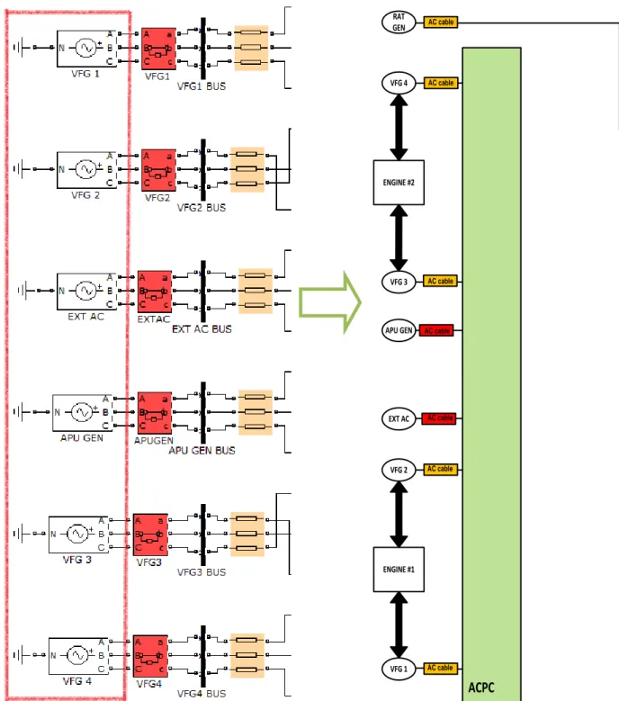
Figure 2.2 shows Three-Phase Programmable Voltage Sources as VFGs within the aircraft electric power system model. The implications of not modeling of VFGs as electrical machines are explained in Chapter 3, section 3.3.
VFG 1 VFG 2 VFG 3 VFG 4 ENGINE #1 ENGINE #2 RAT GEN EXT AC APU GEN ACPC AC cable AC cable AC cable AC cable AC cable AC cable AC cable
Figure 2.2. VGF's block implemented in Simulink and its location in actual aircraft electric power system
2.2.2 AC Power Centre (ACPC)
The AC system architecture is shown by Figure 2.3. A means of connecting External AC power is also provided.
Figure 2.3. ACPC Electrical System schematic [19] Table 2.3 gives the AC contactor logic with APU available
Table 2.3. AC system contactor operation logic with APU available [19]
POWER SOURCE STATUS BUS POWER SOURCE
AC BUS 1 AC BUS 2 AC BUS 3 AC BUS 4 AC ESS BUS
NORMAL VFG 1 VFG 2 VFG 3 VFG 4 VFG 4
VFG 4 FAIL /OFF VFG 1 VFG 2 VFG 3 VFG 1 VFG 1
VFG 3 FAIL /OFF VFG 1 VFG 2 VFG 2 VFG 4 VFG 4
VFG 3 & 4 FAIL /OFF VFG 1 VFG 2 VFG 2 VFG 1 VFG 1
VFG 2 FAIL /OFF VFG 1 VFG 3 VFG 3 VFG 4 VFG 4
VFG 2 & 4 FAIL /OFF VFG 1 VFG 3 VFG 3 VFG 1 VFG 1
VFG 2 & 3 FAIL /OFF VFG 1 VFG 4 VFG 1 VFG 4 VFG 4
VFG 2 & 3 & 4 FAIL /OFF VFG 1 APU APU VFG 1 VFG 1
VFG 1 FAIL /OFF VFG 4 VFG 2 VFG 3 VFG 4 VFG 4
VFG 1 & 4 FAIL /OFF VFG 3 VFG 2 VFG 3 VFG 2 VFG 2
VFG 1 & 3 FAIL /OFF VFG 4 VFG 2 VFG 2 VFG 4 VFG 4
VFG 1 & 3 & 4 FAIL /OFF VFG 2 VFG2 APU APU APU
VFG 1 & 2 FAIL /OFF VFG 4 VFG 3 VFG 3 VFG 4 VFG 4
VFG 1 & 2 & 4 FAIL /OFF APU APU VFG 3 VFG 3 VFG 3 VFG 1 & 2 & 3 FAIL /OFF VFG 4 APU APU VFG 4 VFG 4
ALL VFG FAIL/OUT APU LOST LOST APU APU
APU GEN & ALL VFG
FAIL/OUT LOST LOST LOST LOST RAT
EXTERNAL POWER EXT EXT EXT EXT EXT
ALL VFG FAIL/OFF APU APU APU APU APU
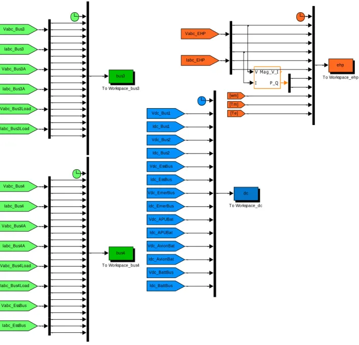
Figure 2.4.ACPC implementation in Simulink
Each switch has a 50 ms time delay which is in fact the maximum switching operation time for power interruptions. Figure 2.5 shows the implementation of the maximum switching time in Simulink. As soon as a VFG failure occurs at a specific time, the switches related to the event operate 50 ms after the failure. This value can be easily changed, since the time delay could be less than 50 ms, depending on the characteristics of the switch.
30 ACBUS4 C 29 ACBUS4 B 28 ACBUS4 A 27 ACBUS3 C 26 ACBUS3 B 25 ACBUS3 A 24 ACBUS2 C 23 ACBUS2 B 22 ACBUS2 A 21 ACBUS1 C 20 ACBUS1 B 19 ACBUS1 A 18 VFG4 C 17 VFG4 B 16 VFG4 A 15 VFG3 C 14 VFG3 B 13 VFG3 A 12 APUGEN C 11 APUGEN B 10 APUGEN A 9 EXTAC C 8 EXTAC B 7 EXTAC A 6 VFG2 C 5 VFG2 B 4 VFG2 A 3 VFG1 C 2 VFG1 B 1 VFG1 A In 1 In 2 In 3 In 4 In 5 In 6 Out 1 Out 2 Out 3 K9 In 1 In 2 In 3 In 4 In 5 In 6 Out 1 Out 2 Out 3 K8 com In 1 In 2 In 3 In 4 In 5 In 6 Out 1 Out 2 Out 3 K7 In 1 In 2 In 3 In 4 In 5 In 6 Out 1 Out 2 Out 3 K6 com In 1 In 2 In 3 In 4 In 5 In 6 Out 1 Out 2 Out 3 K5 In 1 In 2 In 3 In 4 In 5 In 6 Out 1 Out 2 Out 3 K4 In 1 In 2 In 3 In 4 In 5 In 6 Out 1 Out 2 Out 3 K3 In 1 In 2 In 3 In 4 In 5 In 6 Out 1 Out 2 Out 3 K2 com In 1 In 2 In 3 In 4 In 5 In 6 Out 1 Out 2 Out 3 K13 In 1 In 2 In 3 In 4 In 5 In 6 Out 1 Out 2 Out 3 K12 In 1 In 2 In 3 In 4 In 5 In 6 Out 1 Out 2 Out 3 K11 com In 1 In 2 In 3 In 4 In 5 In 6 Out 1 Out 2 Out 3 K10 In 1 In 2 In 3 In 4 In 5 In 6 Out 1 Out 2 Out 3 K1 K13 K10 K7 K5
Figure 2.5. Maximum switching time implemented in Simulink
It is worth noting that generators rotate in opposite directions depending on their location, as explained in Chapter 1, section 1.2.1. Phase sequence of generator 1 and 4 is A, B, C. Phase sequence of generator 2 and 3 is C, B, A. To that effect, phase sequence is corrected by switching A and C phases of generators 2 and 3 in the ACPC. This is implemented in the aircraft electric power system modeled in Simulink, as shown in Figure 2.6. Implications of not modeling this phase sequence are explained in Chapter 3.
![Figure 2.3. ACPC Electrical System schematic [19] Table 2.3 gives the AC contactor logic with APU available](https://thumb-eu.123doks.com/thumbv2/123doknet/2340240.33737/50.918.116.807.232.987/figure-acpc-electrical-schematic-table-gives-contactor-available.webp)
![Table 2.5. Zero Sequence Resistance assuming a perfect ground plane at 20°C and 400 Hz [21]](https://thumb-eu.123doks.com/thumbv2/123doknet/2340240.33737/63.918.211.709.716.997/table-zero-sequence-resistance-assuming-perfect-ground-plane.webp)

![Figure 2.18 presents the EHP model implemented in Simulink, using the Asynchronous Machine [14]](https://thumb-eu.123doks.com/thumbv2/123doknet/2340240.33737/68.918.118.797.549.885/figure-presents-model-implemented-simulink-using-asynchronous-machine.webp)