Study for the Optimization of Interfacial Properties
between Metallic Substrates and Polymeric Coatings by
Plasma-Based Surface Modification Methods to Improve
Performance of Vascular Stents
Thèse
Megan Mahrokh Dorri
Doctorat en génie des matériaux et de la métallurgie
Philosophiæ Doctor (Ph.D.)
Québec, Canada
Study for the Optimization of Interfacial Properties
between Metallic Substrates and Polymeric Coatings by
Plasma-Based Surface Modification Methods to Improve
Performance of Vascular Stents
Thèse
Megan Mahrokh Dorri
Sous la direction de :
Résumé
Au cours de 15 dernières années, les maladies coronariennes et les accidents vasculaires cérébraux demeurent les causes principales de décès dans le monde. Selon l'Organisation Mondiale de la Santé, en 2015, ces deux maladies ont causé 15 millions des décès sur les 56,4 millions dans le monde. Des traitements chirurgicaux ont été élaborés et améliorés pour soigner ces maladies en maintenant les vaisseaux sanguins ouverts.
Parmi les traitements chirurgicaux, l'angioplastie avec utilisation d’un stent est le traitement le plus populaire et le moins invasif. Les stents, qui sont des tubes métalliques en treillis, vont soutenir mécaniquement les vaisseaux sanguins après l’implantation et les maintenir ouverts pour améliorer le flux sanguin. Ceux-ci sont principalement composés d’acier inoxydable AISI316L (SS316L), d'alliage de cobalt-chrome et d'alliage de titane. Depuis plus d'un demi-siècle, lorsqu'un stent a été implanté pour la première fois, ils ont été considérablement améliorés. Cependant, la libération d'ions métalliques, potentiellement toxiques, et la détérioration des propriétés mécaniques à cause de la corrosion ainsi que la diminution de l'adhérence des revêtements, dans le cas de stents avec les revêtements en polymère, constituent encore des préoccupations majeures lors de l’utilisation des stents.
Dans le cas des stents en SS316L, afin d’éviter la libération d'ions métalliques, au laboratoire de biomatériaux et de bioingénierie de l'Université Laval (LBB), lors de précédentes recherches, un revêtement fluorocarboné (CFx) a été étudié pour isoler
complètement le stent de l'environnement biologique. Ce revêtement permet également le greffage ultérieur de molécules bioactives pour améliorer son intégration dans le corps. Cependant, l'interface de SS316L / CFx devait être améliorée pour augmenter l’adhésion
du revêtement CFx sur le SS316L.
Dans mon projet de doctorat, l’oxydation au plasma a été utilisé pour élaborer une nouvelle interface entre le substrat SS316L et le revêtement. Les propriétés de cette nouvelle interface, qui est composée d’une couche d'oxyde, ont été modifiées en faisant varier les paramètres du procédé plasma afin de préserver les propriétés de cette couche d’oxyde lorsqu’elle subit une déformation plastique de 25%, c’est-à-dire le pourcentage
Cette interface a permis de diminuer la libération des ions du substrat SS316L en réduisant son taux de corrosion plus que trois fois et d’améliorer l’adhérence adéquate du revêtement CFx sur le substrat, après déformation et après immersion dans une solution
aqueuse saline. La nouvelle couche d'oxyde sur SS316L est une couche d'oxyde amorphe avec une épaisseur d'environ 6 nm qui se distincte bien de la microstructure polycristalline du substrat. L'amélioration des propriétés de l'interface a été attribuée à cette couche d'oxyde amorphe nano-épaisse, qui est résistante aux déformations plastiques. Cette couche d'oxyde peut être appliquée sur des stents métalliques nus composés de métaux passivables. En outre, elle crée une interface favorable pour les revêtements en polymère, qui sont utilisés pour les stents à relargage de principes actifs ainsi que pour améliorer l'intégration des stents dans le corps humain.
Abstract
Over the past 15 years, ischemic heart disease and stroke have remained the leading causes of death, worldwide. According to the World Health Organization, 15 million of the 56.4 million global deaths, in 2015, were caused only by ischemic heart disease or stroke. For the treatment of these diseases, surgical treatments have been introduced and improved to hold the blood vessels open.
Among the surgical treatments, angioplasty with stenting is the most popular and the least invasive treatments. Stents, which are wire mesh tubes, prepare a mechanical support for blood vessels and hold them open to restore the blood flow. They are mostly made up of AISI316L stainless steel (SS316L), cobalt-chromium, and titanium alloys. More than half a century ago, when a stent first used, it has considerably evolved. However, release of potentially-toxic metallic ions and deterioration of mechanical properties due to corrosion, and decrease of polymeric coatings adhesion, in case of coated stents, still constitute major concerns in SS316L stents.
In the case of SS316L stents, to circumvent the release of metallic ions, in the laboratory for biomaterials and bioengineering of Université Laval (LBB), a fluorocarbon (CFx)
coating was previously investigated to isolate the stent completely from the biological environment. The coating also enables subsequent grafting of bioactive molecules to improve its integration in the body. The results were promising; however, the interface of SS316L/CFx needed to be modified to improve the adhesion of the CFx coating.
In this Ph.D. research project, a new interface between the SS316L substrate and the CFx
coating was created by plasma oxidation. The properties of this new interface, which was an oxide layer, was modified by varying the plasma-process parameters in order to preserve its properties after a 25% plastic deformation. This deformation is the maximum plastic deformation that imposes on a stent during its implantation.
The new interface decreased the release of ions by decreasing the corrosion rate of the SS316L substrate by a factor of three. It was also found that the new interface produced an adequate adhesion of the CFx coating to the substrate after deformation as well as after
amorphous oxide layer with an approximately 6 nm thickness, which was clearly distinguished from the polycrystalline microstructure of the substrate. The enhancement of the interface properties was ascribed to this nano-thick amorphous oxide layer, which was found to be more resistant to plastic deformation. This new oxide layer can be produced on bare-metal stents made of passivating metals. Moreover, it can create a favorable interface for coated stents, which have been used in drug-eluting stents, and also to improve stents integration in the human body.
Table of Contents
Résumé ... iii
Abstract ... v
Table of Contents ... vii
List of Tables ... x List of Figures ... xi Abbreviations ... xiv Acknowledgment ... xviii Preface ... xxii 1 Introduction ... 1
1.1 The Main Pathologies in the Cardiovascular System ... 3
1.2 Atherosclerosis Treatment and Stenting ... 7
1.3 Metal Stents and Stainless Steel 316L ... 11
1.4 Clinical Complications ... 14
1.5 The LBB Project on Nano-Coatings for Stents ... 17
1.6 Thesis Objectives and Strategies ... 20
2 Surface Treatment of Stainless Steel 316L - Literature Review ... 25
2.1 Surface Modification ... 26
2.1.1 Surface Grain Refinement ... 26
2.1.2 Grain Boundary Engineering ... 28
2.1.3 Carburizing and Nitriding ... 34
2.1.4 Selected Surface Modification Method for SS316L ... 38
2.2 Plasma Polymer Coating and CFx ... 39
2.2.1 Nucleation Mechanism ... 43
2.2.2 Polymerization Mechanism ... 44
2.2.3 CFx Coating Adhesion and Permeability ... 46
3 Characterization of Amorphous Oxide Nano-Thick Layers on 316L Stainless Steel by Electron Channeling Contrast Imaging and Electron Backscatter Diffraction ... 49
3.1 Résumé ... 50
3.2 Abstract ... 51
3.3 Introduction ... 52
3.4 Materials and Methods ... 54
3.4.1 Materials and Sample Preparation ... 54
3.4.2 Surface Modification Using Plasma ... 54
3.4.3 EBSD and ECCI Microstructure Characterization ... 55
3.4.4 Oxide Layer Thickness Determination ... 55
3.5 Results and Discussion ... 56
3.5.1 EBSD ... 56
3.5.2 ECCI ... 58
3.5.3 Thickness Measurement ... 60
3.5.4 XPS Depth Profiles ... 67
4 Nano-Thick Amorphous Oxide Layer Produced by Plasma on Stainless Steel
316L for Improved Corrosion Resistance under Plastic Deformation ... 70
4.1 Résumé ... 71
4.2 Abstract ... 72
4.3 Introduction ... 73
4.4 Materials and Methods ... 75
4.4.1 Materials and Sample Preparation ... 75
4.4.2 Surface Modification ... 75
4.4.3 Sample Deformation ... 76
4.4.4 Electrochemical Measurements ... 76
4.4.5 XPS Depth Profiles ... 76
4.4.6 SEM and EDS Characterization ... 77
4.5 Results and Discussion ... 77
4.5.1 OCP and CPP, and Resistance to Pitting Corrosion ... 77
4.5.2 XPS Profile and Composition Change in Depth ... 82
4.5.3 SEM and Pitting Mechanism ... 85
4.5.4 EDS and Over-Saturation of Oxygen ... 88
4.5.5 EIS and Resistance to Permeability ... 89
4.6 Conclusion ... 91
4.7 Acknowledgment ... 92
5 Enhancing the Adhesion of a Fluorocarbon Plasma-Deposited Coating by Producing an Interface of Amorphous Oxide Layer on 316L Stainless Steel for Stent Applications ... 93
5.1 Résumé ... 94
5.2 Abstract ... 95
5.3 Introduction ... 96
5.4 Materials and Methods ... 97
5.4.1 Materials and Sample Preparation ... 97
5.4.2 Characterization of the Coating ... 99
5.5 Results and Discussion ... 101
5.5.1 Surface Morphology ... 101 5.5.2 Chemical Composition ... 103 5.5.3 Corrosion Rate ... 109 5.6 Conclusion ... 111 5.7 Acknowledgment ... 112 6 General Discussion ... 113
6.1 Summary of the Research ... 114
6.2 Challenges and Limits of the Research ... 117
6.2.1 As-received Material ... 117
6.2.2 Pre-treatment and Electropolishing ... 118
6.2.3 Plasma Reactor ... 119
6.2.4 Electrochemical and Corrosion Experiments ... 120
6.3 Perspectives and Suggestions ... 122
7 Conclusion ... 123
8 Annexes: ... 126
8.1 Electrochemical Experiments in the Laboratory ... 126
8.1.1 Properties of the Electrode ... 126
8.1.3 Electrochemical Testing Methods ... 138
8.1.4 Standard Test Procedures ... 144
8.2 Corrosion Principles of Stainless Steel ... 146
8.2.1 Thermodynamics of Corrosion and Pourbaix Diagrams ... 146
8.2.2 Metallurgical Aspects of Corrosion ... 150
8.2.3 Electrochemistry of Corrosion ... 152
8.2.4 Passivity ... 154
8.3 Corrosion of Stainless Steel ... 156
8.3.1 Forms of Corrosion ... 156
8.3.2 Pitting Corrosion ... 161
List of Tables
Table 1.1. Historical milestones in coronary artery stenting (reproduced from the
reference).19 ... 10
Table 1.2. Materials for durable bare stents, characteristics and disadvantages. ... 12
Table 1.3. Mechanical properties of most common stent materials.36 ... 13
Table 1.4. Chemical composition of SS316L.40 ... 14
Table 2.1. Comparison of different SS316L surface modification techniques to improve the corrosion properties. ... 35
Table 3.1. Electron-beam accelerating voltage corresponding to the signal-to-noise ratio threshold of 0.05 (threshold voltage, kV) for the EBSD and ECCI results related to the electropolished (EP), room-oxidized (RO), and plasma-oxidized (PO) samples. ... 62
Table 3.2. Amorphous oxide layer thickness deduced from the Monte Carlo calibration curves for the signal-to-noise ratio (SNR) threshold of 0.05. ... 66
Table 3.3. Elapsed sputtering time to reach the half-maximum of the oxygen concentration. ... 68
Table 4.1. Summary of the polarization results. ... 82
Table 4.2. Chemical composition of the areas (A1, A2 and A3) and the spots (S1, S2 and S3), marked on Figure 4.6. ... 89
Table 5.1. Plasma process parameters. ... 98
Table 5.2. Samples preparation steps. ... 99
Table 5.3. Surface chemical composition by XPS*. ... 104
Table 5.4. XPS surface chemical composition at different take-off angles. ... 109
Table 8.1. PBS composition... 133
Table 8.2. Heterogeneity in metals.87 ... 151
List of Figures
Figure 1.1. Proportion of global deaths under the age 70 years, by cause of death,
comparable estimates, 2012 (reproduced from the reference).1 ... 1
Figure 1.2. Projected CVD deaths 2015-2030 by World Health Organization regions (AFR: African Region, AMR: Region of the Americas, EMR: Eastern Mediterranean Region, SEAR: South-East Asia Region, WPR: Western Pacific Region).3 ... 2
Figure 1.3. The cost of noncommunicable diseases for all low and middle-income countries, by disease and income level.3 ... 3
Figure 1.4. Structure of blood vessels.6 ... 4
Figure 1.5. Atherosclerosis and narrowing of the arterial lumen.9 ... 6
Figure 1.6. The site of an atherosclerotic plaque.9 ... 7
Figure 1.7. Stenting procedure.18 ... 9
Figure 1.8. Repartition of FDA/CE approved stent materials in 2012 (reproduced from the reference).25 ... 13
Figure 1.9. The etiology of in stent chronic total occlusion, a) BMS and b) DES.52 ... 16
Figure 1.10. Brief schematic of different stages of the project history in the LBB, a) as-received SS316L sample, b) electropolished and acid dipped sample,58, 64 c) CFx coating plasma deposition on the substrate of electropolished SS316L,57 d) deformation of the sample by the small punch test,60 e) creating the cracks on the CFx coating after deformation,61 f) plasma etching of the SS316L surface after electropolishing and then deposition of CFx coating,63 g) corrosion of the coated sample which led to release of metal ions through the nano-pores in the CFx coating,63 and h) presence of blisters on the CFx coating after aging test.65 ... 19
Figure 1.11. Brief schematic of different steps of this Ph.D. research, a) as-received SS316L sample, b) electropolished and acid dipped sample, c) deposition of CFx coating on the plasma-etched SS316L substrate, which shows release of ions through the nano-pores of the coating (related to the last step in the previous research in the LBB), d) deposition of CFx coating on plasma-oxidized SS316L substrate after the plasma etching, e) decrease of the release of ions, f) increase of the ions release after deformation of the sample, g) modification of the plasma-oxidized substrate, h) decrease of the ions release even after deformation, and i) presence of no blister on the CFx coating that shows adequate adhesion of the CFx coating on the new substrate. ... 22
Figure 2.1. XPS results from a passive film formed in a 0.1 M HCl-0.4 M NaCl solution and in the high passive region. The oxide film is found to be strongly enriched in chromium, whereas the metal/film interface is strongly enriched in nickel. The passive film itself shows no incorporation of nickel.68, 89 ... 32
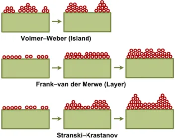
Figure 2.2. Basic modes of thin-film nucleation and growth.130 ... 44
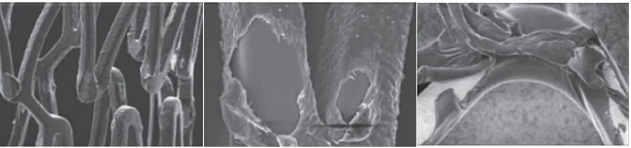
Figure 2.3. Examples of commonly encountered coating defects, where the polymer matrix has delaminated from the stent.141 ... 47
Figure 2.4. Examples of different structures of ePTFE.143 ... 47
Figure 3.1. EBSPs of the EP (a), RO (b), and PO (c) samples at electron-beam accelerating voltages of 2, 3, 5 and 20 kV (EP: electropolished, RO: room-oxidized, and PO: plasma-oxidized). ... 58
Figure 3.2. ECCI micrographs of the EP (a), RO (b), and PO (c) samples at
electron-beam accelerating voltages of 1, 2 and 5 kV (EP: electropolished, RO: room-oxidized, and PO: plasma-oxidized). ... 59 Figure 3.3. SNR threshold determination for the measurement of the amorphous oxide
layer. a, b: SNR as a function of the Gaussian noise factor with the SNR threshold for ECCI (a) and EBSD (b) corresponding to the dotted lines; (c, d) SNR as a function of electron-beam accelerating voltage for ECCI (c) and EBSP (d) images of different samples. ... 61 Figure 3.4. Example of the maximum depth distribution obtained by Monte Carlo
simulation with MC X-ray161 for a typical stainless steel (Cr = 18 wt%, Ni = 14 wt% and Fe = 68 wt%) as the substrate covered with an oxide layer (FeO-CrO) of 7 nm thick at 1, 2 and 5 kV electron-beam accelerating voltages at 0° tilt angle and comparison with their corresponding ECCI images for the PO sample. ... 64 Figure 3.5. Thickness calibration curves as a function of the electron-beam accelerating
voltage obtained by Monte Carlo simulations for the EBSD and ECCI set-up. The thickness was defined as the maximum depth in the Z direction normal to the sample surface, as experienced by the low-loss BSE. ... 65 Figure 3.6. XPS depth profiles of the RO (a), EP (b), and PO (c) samples (EP:
electropolished, RO: room-oxidized, and PO: plasma-oxidized). ... 68 Figure 4.1. OCP and CPP results of a1, a2) the plasma oxidized samples for 5, 10, 15 and
30 min (PO-5, PO-10, PO-15 and PO-30) in comparison with the EP sample; b1, b2) PO-10 at -100 (self-bias), -200 and -300 V biases; c1, c2) PO-10 before and after deformation. The data were measured in a deaerated PBS solution at 37 °C and a pH of 7.4. ... 81 Figure 4.2. XPS depth profiles of the electropolished (EP), plasma oxidized for 5 and 10
min (PO-5 and PO-10) samples for atomic compositions of a) oxygen, b) iron, c) chromium, and d) nickel. ... 84 Figure 4.3. SEM micrographs of pits occurred after CPP on the samples a)
electropolished and b) plasma-oxidized for 30 min. ... 86 Figure 4.4. SEM micrographs of volcano-shape pits occurred after CPP on the
plasma-oxidized for 30 min sample. ... 87 Figure 4.5. SEM micrographs of the deformed sample, plasma-oxidized for 30 min, a)
before and b) after CPP, the arrows show the possible initiation sites of pitting corrosion. ... 87 Figure 4.6. SEM micrograph of a volcano-shape pit occurred after CPP on the
plasma-oxidized for 30 min sample, and the sites of EDS analyses. ... 88 Figure 4.7. a) Nyquist, b) Bode phase and c) Bode impedance plots of the electropolished
(EP), and plasma oxidized for 5, 10, 15 and 30 min (PO-5, PO-10, PO-15 and PO-30) samples. The spectra were recorded in a deaerated PBS solution at 37 °C and pH of 7.4. ... 90 Figure 5.1. AFM images of the coated samples for two interfaces of etched
(etched+CFx), and etched and plasma oxidized (etched+PO+CFx), for both deformed and non-deformed ones, after aging for 2 weeks in the PBS
Figure 5.2. XPS high-resolution spectra of C1s region of CFx coatings for the a1) and b1)
as-deposited, a2) and b2) as-deposited and aged, a3) and b3) deformed, and a4) and b4) deformed and aged, for two interfaces of etched+CFx (column a)
and etched+PO+CFx (column b). The binding energies were assigned as
following: BE = 285 eV to C-C/C-H, BE = 287 eV to C-CF/C-O, BE = 289.5 eV to CF/C=O, BE = 292 eV to CF2, and BE = 294 eV to CF3. ... 106
Figure 5.3. Representative XPS O1s spectra obtained from non-deformed a1) and b1) as-deposited, and a2) and b2) as-deposited and aged, for two interfaces of etched+CFx and etched+PO+CFx, respectively. Both peaks of O-C and O-F
shifted towards lower binding energies after aging, in both interfaces, as shown with arrows. The binding energies were assigned to different
components as following: BE = 530-531 eV to HO-M, BE = 531-533 eV to O-C, and BE = 533-534 eV to O-F. ... 107 Figure 6.1. Surface microstructure of the as-received sample a) solution annealed and b)
dry annealed. ... 118 Figure 6.2. AFM images (20 µm × 20 µm) of a) electropolished sample and b)
electropolished and cleaned in an ultrasonic bath. ... 119 Figure 6.3. The corrosion test sample holder, the explanation in section 6.2.4.2 is on the
“gasket”. ... 121 Figure 8.1. Effect of chromium content on Fe-Ni-Cr alloys on their anodic polarization
curve in a 2N H2SO4 solution at 90°C.246 ... 127
Figure 8.2. Schematic summary of the effect of alloying elements in stainless steel on the anodic polarization curve.246 ... 128 Figure 8.3. Schematic anodic polarization curves for stainless steels in a neutral chloride
solution and a strong hydrochloride acid solution.246 ... 136 Figure 8.4. Schematic representation of anodic polarization curves for metal immersed in
a solution containing aggressive ions.251 ... 139 Figure 8.5. SEM image of the top of the foil showing the perforated cover, (below)
radiograph of the final shape of pit. The scale bar for both micrograph is identical. The dashed lines correlate the pit width in both.194 ... 142 Figure 8.6. Nyquist diagram showing that pitting decreases the charge transfer resistance
from Rt1 to Rt2. ... 143
Figure 8.7. Geometry of crevice corrosion.247 ... 146 Figure 8.8. Multi-elemental Fe-Cr Pourbaix diagram at a composition of 18% Cr, 82%
Fe.260 ... 149 Figure 8.9. Schematic of the events happening during pitting corrosion.244 ... 163 Figure 8.10. Penetration mechanism and phase diagram of a passive film with related
processes of ion and electron transfer within the film and at its phase
boundaries.272 ... 164 Figure 8.11. Adsorption mechanism with increased local transfer of metal ions and
related corrosion current density, ic, caused by complexing aggressive anions
leading to thinning of the passive layer and increases in field strength and final free corrosion current density ic,h within the pit.272 ... 165
Figure 8.12. Mechanical film breakdown mechanism and related competing processes.272
Abbreviations
Below is a list of abbreviations and terms used throughout this project. The large majority of them are defined in the body of the thesis and are grouped here for the ease of reference.
AFM atomic force microscopy AGM activated growth model ALD atomic layer deposition
AR-XPS angle resolved X-ray photoelectron spectroscopy ASTM American Society for Testing and Materials BSE backscattered electrons
BMS bare-metal stents
CE Conformité Européene
CFx fluorocarbon
CPP cyclic potentiodynamic polarization CVDs cardiovascular diseases
DES drug-eluting stents
DLC diamond like carbon
EBSD electron backscatter diffraction EBSPs electron backscatter patterns
ECCI electron channeling contrast imaging EDS energy dispersive spectroscopy
EIS electrochemical impedance spectroscopy ENM electrochemical noise measurements
EP electropolished
FDA Food and Drug Administration GAXRD glancing angle X-ray diffraction ISR in stent restenosis
LBB Laboratory for Biomaterials and Bioengineering of Université Laval LEED low energy electron diffraction
MC X-ray Monte Carlo X-ray
NACE TM National Association of Corrosion Engineers test method NCDs noncommunicable diseases
OCP open circuit potential PAC plasma activated coating PBS phosphate buffered saline
PCI percutaneous coronary intervention
PO plasma oxidation/oxidizing/oxidized PSM plasma surface modification
PTFE polytetrafluoroethylene PVD plasma vapour deposition
RO room oxidation
SCE saturated calomel electrode S phase single phase/expanded austenite SEM scanning electron microscopy SS316L AISI 316L stainless steel
TEM transmission electron microscopy XPS X-ray photoelectron spectroscopy
Education is not the learning of facts, but the training of the mind to think. Albert Einstein
Acknowledgment
I would like to express my sincere gratitude to my supervisor, Professor Diego Mantovani, director of the Laboratory for Biomaterials and Bioengineering (LBB) at Université Laval for his support and guidance throughout my PhD studies. I feel privileged and honored to be his student. I thank him for instilling in me strong critical thinking skills that will be invaluable throughout my life. I hope to adopt his strong work ethic and integrity in my future endeavors. I learned many things in his laboratory along with such nice and professional team members. Apart from scientific matters, I was also taught many life lessons that I will continue to use in my life. Without Diego’s sustained generosity, encouragement, guidance, and patience, it would not have been possible for me to succeed.
I would also like to thank my distinguished jury members Professor Emile Knystautas, Professor Wojciech Simka, and Professor Luc Stafford. I appreciate their time for thoroughly reading my thesis and for their thoughtful and positive comments. Thanks to Professor Emile Knystautas for the prereading of my thesis. Thanks to Professor Gaétan Laroche for being the president of the jury. I feel honored to be considered worthy of their presence.
I am particularly grateful to Doctor Stéphane Turgeon, professional researcher in the LBB, who I considered to be my unofficial cosupervisor. I deeply appreciate the knowledge and experience I have gained from his vast insight in plasma technologies and interfacial engineering. Stéphane taught me how lab equipment works and how to maintain it. He is an outstanding physicist and I was lucky to have his help and companionship in scientific discussions. Moreover, his friendship is my most valuable treasure.
Doctor Pascale Chevallier, professional researcher in the LBB, has always cared and helped me accelerate in my research. I would like to thank her for her support, especially for her comments and corrections on our articles. I learned valuable knowledge from her as a chemist. I enjoyed working with her.
I would like to thank Doctor Ranna Tolouei for all of her support and all the nice discussions that we had. I learned valuable things from her especially on improving my communication skills.
I thank Doctor Carlo Paternoster for all the helpful discussions that we had and for his friendship.
Daniel Marcotte, technician in teaching and research, was always helpful. He is very generous with his knowledge and experience. Students are lucky to have him. I appreciated his knowledge and know-how. Many thanks to Daniel.
I wish to thank other professional researchers Andrée-Anne Guay-Begin and Lucie Levesque. Thank you for your help during my days working in the laboratory.
Many thanks to my colleagues and friends, past and present, at the LBB and at the university. Thank you to Linda, Malgo, Livia, Juliana, Clayton, Farid, Agung, Betul, Nicolas, Giovana, Erica, Julian, Sergio, Carolina, Ivan, Eleonore, Caroline, Pedram, Dimitria, Marie-Claire, Vanessa, Essowe, Carlo, Michel, Samira, Majid, Sebastien and Marie, Ranna and Maryam, Maxime, Samira, Reza, Francesco, Daniele, Dawit, Ludivin, Saeideh, Bahareh, Sheida and Mousa, Kamran, Pouyan, and Majid. I had great experience working in the same vicinity as all of you.
I was lucky to have the friendship of Doctor Stéphanie Vanslambrouck who shared an office with me. Stéphanie is a great person and many thanks for helping me with my French. I appreciated her presence and her down-to-earth personality.
I wish to say a special thanks to Doctor Maxime Cloutier. Maxime was the one who first showed me the lab and introduced me to the project.
A special thanks to Doctor Remi Martinez for his belief in me and his support.
Thank you to the following university technicians: Vicky Dodier, Nathalie Moisan, André Ferland, and Jean Frenette. You were a big help.
Thank you to the administrative and support staff: Ginette, Andrée, Martine, Karine, and Richard Rehel. Your help is deeply appreciated.
Many warm thanks go to the security guards and the custodians who took care of the lab. I appreciate them every day.
I would also like to thank the following professors of the department who I learned from: Professor Marc-Andre Fortin, Professor Edward Ghali, and Professor Hendra Hermawan. I would like to especially thank my two English teachers Erica Pridoehl, M. Ed. English Tutoring, and Robert Jardine for editing most parts of the manuscripts. I would also like to thank them for helping me to improve my English writing skills and pronunciation. I would like to acknowledge Distinguished Toastmasters at the Universtié Laval Toastmasters. Thank you to Robert Wayne Fielding (Eng.), Luc Pelletier (Eng.), Jean Racine, and Professor Désirée Maltais for their help on improving my communication and leadership skills.
I especially appreciate my French and English Canadian friends for their support. They are supportive and friendly and I thank them for giving me the possibility to know the Canadian culture, a culture that I admire. Many thanks to them for accepting me in this beautiful country and province. It is here in Québec that I started to understand myself better and improve my personality and professional skills. I felt free here and I flourished. I would like to acknowledge the partial funding from the Canada Research Chairs, le Fonds de recherche sur la nature et les technologies, le Centre québecois sur les matériaux fonctionnels, le Centre de recherche de Québec, le Centre de recherche sur les matériaux avancés, and the Natural Sciences and Engineering Research Council of Canada. I would also like to thank the Québec government and Caisse Desjardins for their financial support.
Thank you to my previous professors, supervisors, and work managers in Iran, Professor Hamid Mirzadeh, Professor Ramin Raiszadeh, Professor Fathollah Moztarzadeh, Professor Soheila Salahshour Kordestani, Doctor Bahram Bahrami, Maryam Maradian (Eng.), Farhad Mehrabi (Eng.), Farhad Senemar (Eng.) for their endless support and encouragement.
Thanks to my dearest friend Mona Enayati. She studied in physics and industrial engineering and is also a Sedona Life Coach. I thank her for her continuous support using
the method which helped me reduce stress and have a better focus throughout my research. Thanks to Mona, guided meditation and the work we did together, I could have a more smooth workflow and enjoy living and working in present moment. You helped me release tension and focus on my research. I highly appreciate your time and support, my dear Mona.
I would like to thank my two great friends from my bachelor studies, Leila and Zhaleh, who are my sisters by heart. They were always there for me to give me positive energy, emotional support, and encouragement. I appreciate your presence.
Thanks to my following friends all over the world: Atossa, Fanayé, Negin, Laleh, Bita, and Shadgin for their emotional support and for encouraging me to fulfill my potentials and abilities.
Thanks to my dear friend John Patrick for his support in the last months of my PhD studies. He gave me joy and happiness to keep going and continuing in my path.
Thanks to my dearest family members Fariba, Maryam, Mobina, Meisam, Atefe, Samira, Ali, Elham, Mahdi, Mahtab, Behrad, and Armin for always being there for me, for being generous in supporting me emotionally and financially. You have all given me so much support and encouragement and I cannot thank you enough.
Thank you to my cousins in the USA, and especially my dear aunt Azam. They have always been there to support, love, and encourage me during my challenging life in Canada.
Finally and most of all, I would like to thank my parents for their unconditional love, support, and encouragement. Thank you one million times for being so patient and understanding while I have been away. I have always had their support and love during these years. I would like to thank them for raising me in a healthy and hard-working environment. I was happy, intellectually stimulated, and dedicated to education. No words are able to describe how much they both mean to me.
Please forgive me if I missed to include your name in this acknowledgment. Please be sure that I have gratitude for your impact on my life.
Preface
This Ph.D. project was carried out in the Laboratory for Biomaterials and Bioengineering of Université Laval (LBB). The project was a continuation of a multivalent long-term project in the laboratory to decrease the clinical complications of permanent, stainless steel stents. Stents are biomedical devices, which are implanted into the blood vessels to hold them open and to restore the blood flow. Therefore, the general objective of this long-term project was to encapsulate the stainless steel substrate with a fluorocarbon polymer coating, to modulate the contact of the stent with the human body. Previous results were promising, which led the project to the following steps, which are the objectives of this thesis research.
In this thesis, the main focus was on enhancing the properties of the interface between the stainless steel substrate and a fluorocarbon coating to attain three main objectives: 1) to decrease the release of potentially toxic ions from the stainless steel substrate, 2) to preserve the properties of the modified surface after a relevant clinical deformation, and 3) to create an adequate adhesion between the coating and the substrate. These features needed to be preserved after the deformation and also after immersing the coated samples in a saline aqueous solution.
To attain the objectives, the first step was characterization of the stainless steel surface, which had been previously treated by plasma-based treatments. In this step, a surface characterization method for nano-thick amorphous layers was introduced. This method is not limited to its application in this research, but can also be used for microstructure characterizations and measuring the thickness of any amorphous layer on a polycrystalline substrate. In the next stages of the research, all three objectives were accomplished. The second stage resulted in a plastic-deformation resistant, nano-thick amorphous oxide layer that not only produced an adequate interface for the fluorocarbon coating, but also can be created on metallic platform for bare-metal stents.
The related experiments and results are exhibited in different chapters of this thesis. The thesis starts with an introduction on the subject, the problematic and the objectives of the project, which are accessible in Chapter 1. Chapter 2 presents a summary of the literature review on the surface modification and surface engineering methods with focus on
stainless steel for biomedical applications. The experimental, obtained results, and discussions are brought in detail in the following three chapters.
Chapter 3: Characterization of Amorphous Oxide Nano-Thick Layers on 316L Stainless Steel by Electron Channeling Contrast Imaging and Electron Backscatter Diffraction Authors: Megan Mahrokh Dorri, Stéphane Turgeon, Nicolas Brodusch, Maxime Cloutier, Pascale Chevallier, Raynald Gauvin, and Diego Mantovani
Journal: This article was published in the journal of Microscopy and Microanalysis, 22 (5), 997-1006 (2016). doi: 10.1017/S1431927616011612.
The primary plasma process parameters were previously developed in the LBB by MC et al. MMD, ST, and PC designed the experiments. The principle characterization methods were proposed by MMD affected by the guidance and teachings of ST. Sample preparation, surface modifications, and corrosion experiments were conducted by MMD. ST did the acquisition of the X-ray photoelectron spectroscopy depth profiles. NB conducted the electron backscatter diffraction (EBSD) and electron channeling contrast imaging (ECCI). The results were firstly prepared and interpreted by MMD and then discussed by all the authors. NB prepared the ImageJ interpretations and MMD helped with the Monte Carlo simulations. The first manuscript was prepared by MMD and NB helped with writing the ECCI and EBSD part in the introduction. All the authors implicated and collaborated in the discussion and analysis of the results and in the improvement of the manuscript.
Chapter 4: Nano-Thick Amorphous Oxide Layer Produced by Plasma on Stainless Steel 316L for Improved Corrosion Resistance under Plastic Deformation
Authors: Megan Mahrokh Dorri, Stéphane Turgeon, Maxime Cloutier, Pascale Chevallier, Diego Mantovani
Journal: This article was submitted to the Corrosion (The Journal of Science and Engineering), October 02, 2017.
The experiments were designed by MMD with the help of MC. The sample preparation, surface modifications by plasma, electrochemical experiments, analysis by scanning electron microscopy, and energy dispersive spectroscopy were carried out by MMD. ST
conducted the X-ray photoelectron spectroscopy depth profiles. The results were prepared and analyzed by MMD and verified by ST. All the authors actively collaborated in the discussion of the results and analyses. MMD wrote the first draft of the manuscript and then all the authors commented, corrected, and ameliorated the article.
Chapter 5: On the Stability and Adhesion of Plasma Fluorocarbon Coating by Creating an Interface of Amorphous Nano-Thick Oxide Layer on Stainless Steel 316L
Authors: Megan Mahrokh Dorri, Pascale Chevallier, Stéphane Turgeon, Diego Mantovani
Journal: This article was submitted to Surface and Coatings Technology journal, November 15, 2017.
The design of experiments, sample preparation, and all the electrochemical experiments, and atomic force microscopy analyses were conducted by MMD. PC and ST carried out the X-ray Photoelectron Spectroscopies, surveys and Angle-Resolved. The results were prepared and analyzed by MMD at first and then PC and ST helped generously to complete the analyses and discussion. The first draft of the article was written by MMD. All the authors helped with its verfication and correction.
1 Introduction
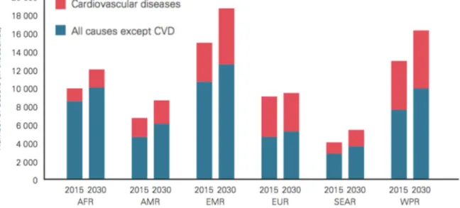
Noncommunicable diseases (NCDs) are of long duration and are generally slow in progression. They are also known as chronic diseases and are not contagious. The four main types include cardiovascular diseases (e.g. heart attacks and stroke), cancer, chronic respiratory diseases (e.g. chronic obstructed pulmonary disease and asthma), and diabetes. In 2012, more than half of the deaths under the age of 70 were due to NCDs. More than one-third of the deaths were caused by cardiovascular diseases (CVDs), as illustrated in Figure 1.1.1 CVDs remain the cause of 17.5 million deaths each year, which is approximately one-third of all deaths, worldwide. If current trends continue, the annual number of deaths from CVDs will rise to 23.6 million by 2030 (Figure 1.2).2
CVDs, which are disorders of the heart and blood vessels, include coronary heart disease, cerebrovascular disease, rheumatic heart disease, and other conditions. Four out of five deaths, that are caused by CVDs, are due to heart attacks and strokes. Of these, an estimated 7.4 million deaths were due to coronary heart diseases and 6.7 million were due to strokes. These are projected to remain the single leading causes of death, globally.3 In Canada, CVDs related to heart attacks and strokes are the leading cause of death of over one-third of the population, according to Statistics Canada. Heart attacks and strokes not only affect the elderly, but are also the third leading cause of premature death under the age of 75.4
Figure 1.1. Proportion of global deaths under the age 70 years, by cause of death, comparable estimates, 2012 (reproduced from the reference).1
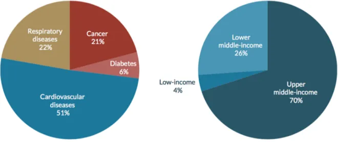
Furthermore, CVDs put a great burden on the health care system, worldwide. According to the World Economic Forum and the Harvard School of Public Health, more than 50% of the 2011 cost for NCDs was spent on CVDs (Figure 1.3).5 CVDs are the most costly disease in Canada and put a great financial burden on the national health care system. In 2000, CVDs were the second most costly contributor to the total health costs in Canada ($22.2 billion), including $7.6 billion in direct costs and $14.6 billion in indirect costs. In the same year, hospital care was the largest contributor to CVDs health care costs ($4.0 billion). Drug costs ($2.1 billion) contributed more than physician care ($1.5 billion). Premature death due to CVDs contributed an estimated $9.3 billion in lost productivity. An additional $4.2 billion was lost due to long-term disability and $1.2 billion to short-term disability.4
Figure 1.2. Projected CVD deaths 2015-2030 by World Health Organization regions (AFR:
African Region, AMR: Region of the Americas, EMR: Eastern Mediterranean Region, SEAR: South-East Asia Region, WPR: Western Pacific Region).3
According to a recent 2016 report by the Heart and Stroke Foundation of Canada, it was found that more than half a million Canadians are currently living with heart failure. There are four main points mentioned in the report: 1) heart failure is on the rise in Canada, 2)
50,000 Canadians are diagnosed each year with heart failure, 3) one in two Canadians has been touched by heart failure, and 4) heart failure costs more than $2.8 billion per year.
Figure 1.3. The cost of noncommunicable diseases for all low and middle-income
countries, by disease and income level.3
1.1 The Main Pathologies in the Cardiovascular System
The cardiovascular system, as one of the most important systems in the human body, is composed of the heart, blood, and blood vessels which distribute oxygen and nutrition to the organs. The vascular system is a network of blood vessels, which are categorised into three important kinds of vessels: arteries, veins and capillaries. Large arteries exit the heart and branch out to narrower and narrower arteries that lead to capillaries, where the exchange of materials happens between the capillaries and tissues. Capillaries merge and lead to tiny venules, which merge to larger and larger veins until they finally pump back into the heart. Structure of vessel walls, except for the tiniest, are composed of these three "tunics" (layers):
• Tunica interna/intima, the innermost layer is made of an endothelium of connected cells; forms a smooth, flat and low friction surface. All vessels have this
layer and a basement membrane associated with the endothelium, except for the tiniest.
• Tunica media is made of a smooth muscle and elastic connective tissue surrounding the interna. It is responsible for vasoconstriction and vasodilation. • Tunica adventitia/externa is a connective tissue with collagen and some elastin,
which surrounds the entire vessel (Figure 1.4).
Capillaries are the smallest vessels and are made of one layer of endothelium and a basement membrane (Figure 1.4). Capillaries serve cells throughout the body via exchanging gases, nutrients and wastes with those cells. On average, the distance between every cell of the body and a capillary is no more than the diameter of three cells.6
Figure 1.4. Structure of blood vessels.6
CVDs are a group of disorders of the heart and blood vessels and can be divided into the following categories:
• Ischemic heart disease or coronary artery disease is a disease of the blood vessels
that supply nutrition and oxygen to the heart muscle (e.g. heart attack).
• Cerebrovascular disease is a disease of the blood vessels that supply nutrition and oxygen to the brain (e.g. stroke).
• Diseases of the aorta and arteries, including hypertension and peripheral vascular disease are diseases of blood vessels that supply nutrition and oxygen to the arms and legs.
• Congenital heart disease is malformations of heart structure existing at birth.
• Rheumatic heart disease is damage to the heart muscle and valves resulting from rheumatic fever.
• Cardiomyopathies are diseases of the heart muscle.
• Cardiac arrhythmia is a of cardiac dysrhythmia or irregular heartbeat.
• Deep vein thrombosis and pulmonary embolism are blood clots in the leg veins, which can dislodge and move to the heart and lungs.7
The first three categories are caused by significant or prolonged interruption of the blood supply to tissues, organs or limbs. Interruption of the blood supply usually results in irreversible damage to at least some cells and may compromise the entire structure. If a vital organ such as the heart, brain or kidney is involved, death can result. Therefore, diseases that affect the circulation are among the most significant and serious of all, and their prevention and treatment play a major role in a human life.
As early as the nineteenth century, pathologists recognized that the arteries of the elderly often lose their elasticity and become narrowed in lumen. They also observed that these degenerative changes, which they termed arteriosclerosis (literally hardening of the arteries), are often associated with ischemia of the tissues. During the twentieth century, advances in microscopy and biochemistry led to the discovery that most cases of arteriosclerosis are due to deposits of lipid material (cholesterol) in the walls of medium and large-sized arteries. This commonest type of arteriosclerosis was termed atherosclerosis, from a Greek word meaning gruel and refers to the gritty and pasty consistency of the lipid deposits.8
Atherosclerosis is a complex pathological process that develops over many years. In this process, the formation of plaque in the inner lining of artery causes narrowing of the lumen (Figure 1.5). The plaque consists of low-density lipoproteins, decaying muscle cells, fibrous tissue, and clumps of blood platelets, cholesterol and sometimes calcium. This plaque thickens and hardens the artery and can partially (stenosis) or totally (occlusion) block the blood flow through it. This decrease in the blood flow to organs (ischemia) prevents their oxygen supply (hypoxia) and nutrients, which can cause a heart attack.8 Figure 1.6 shows the position of a blocked coronary artery in the heart.
Figure 1.5. Atherosclerosis and narrowing of the arterial lumen.9
Furthermore, plaque causes a loss of the smooth lining of endothelium in blood vessels and encourages formation of blood clots (thrombi). Sometimes fragments of thrombi break off and form emboli, which travel through the bloodstream and can cause obstruction of a smaller arterial branch. In addition, inflammatory and degenerative changes in and around the plaque can lead to local hemorrhage or dissection.8, 10
CVDs risk factors contain behavioural and physiological factors. Behavioural factors involve tobacco use, an unhealthy diet, harmful use of alcohol, and inadequate physical activity. Physiological factors contain high blood pressure (hypertension), high blood cholesterol, and high blood sugar or glucose, which are linked to underlying social determinants and drivers. These can all be easily measured in primary care facilities. Identifying those at highest risk of CVDs and ensuring they receive appropriate treatment can prevent premature deaths. Although a large proportion of CVDs is preventable, they continue to rise mainly because of inadequate preventive measures.11
Figure 1.6. The site of an atherosclerotic plaque.9
1.2 Atherosclerosis Treatment and Stenting
Millions of people worldwide struggle to control the risk factors that lead to CVDs, many others remain unaware that they are at high risk. A large number of CVDs, heart attacks and strokes, can be prevented by addressing behavioural risk factors through lifestyle interventions and, where necessary, through drug treatment. The benefits of these interventions are largely independent, but when used together with smoking cessation, nearly 75% of recurrent vascular events may be prevented. Currently, there are major gaps
in the implementation of these interventions particularly at the primary health care level. The prevention of atherosclerosis is a high-priority objective for modern medicine. Apart from prevention methods and a primary health-care approach to strengthen early detection and timely treatment, costly surgical operations are sometimes mandatory to treat CVDs. In case of heart diseases possible operations include the following cases:
• Coronary artery bypass • Balloon angioplasty
• Valve repair and replacement • Heart transplantation
• Artificial heart operations
Furthermore, medical devices such as pacemakers, prosthetic valves, and patches for closing holes in the heart could be required.12
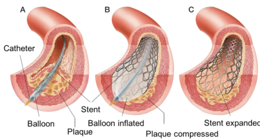
Balloon angioplasty is the most usual intervention for reopening narrowed or blocked arteries (e.g. coronary arteries) without major surgery. Angio means relating to a blood vessel and plasty means repair. Balloon angioplasty is also sometimes called percutaneous transluminal coronary angioplasty (PTCA) or percutaneous coronary intervention (PCI). In this operation, the surgeon makes a small incision in the groin or arm and threads a thin tube, called a catheter, into the artery. Once the catheter that includes a small balloon on its head is in place, a dye is injected and X-rays are taken. This procedure can tell the physician exactly where the blockages are and how narrow the artery is. After, the balloon is inflated and pushes the plaque against the artery wall and reopens the artery.11
It is hoped that the vessel remains open when the balloon is deflated and removed, although this is not always the case. If the vessel is not permanently deformed by the balloon inflation, it will return to its previous blocked state, which is called elastic recoil. Even if the artery remains open initially, it may occlude weeks or months later due to tissue proliferation, which is called restenosis. Restenosis is caused by hyperplasia and arterial remodelling, which occurs in three to six months after the PCI procedure in about 40% of the patients.13 The other problem of PCI is abrupt vessel closure occurring in a small percentage of the patients that occurs in 24 hours after the procedure. To prevent these
situations, there are other types of angioplasty that are sometimes used in combination with the balloon angioplasty:
• Directional atherectomy involves using a miniature rotating blade to cut out the fatty deposit and remove it from the body.
• Excimer laser angioplasty uses a laser to remove the blockage in the artery. Usually, the balloon is used to help make the space through the blockage larger. • Rotational atherectomy engages using a diamond-studded drill bit to pulverize
tough blockages.
• Intracoronary radiation involves irradiation of a section of the artery after balloon angioplasty. Studies show this experimental technique reduces renarrowing in the artery by 70%.
• Stenting involves using a stent, which is an expandable wire mesh tube and is placed within a diseased artery to maintain its patency.14
Among these angioplasty methods, stenting is presently performed in more than 60% of the balloon angioplasty cases.13, 15 In this procedure, the stent is mounted on the balloon and is positioned and expanded by inflating the balloon. As shown in Figure 1.7, expansion of a stent pushes it up against the artery wall and when the balloon is deflated the stent remains in place as a scaffold and holds the artery open.16 By stenting, the risk of the artery re-narrowing and abrupt vessel closures during or within 24 hours of the procedure is nearly eliminated.17
Figure 1.7. Stenting procedure.18
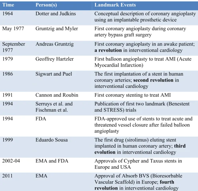
“Coronary angioplasty, conceptually was described by Dotter and Judkins in 1964, was first performed by Andreas Gruntzig in 1977. Coronary stents were developed in the mid-1980s and since then have seen major improvements in design and composition.”19 The landmark events in the history of stent development are shown in Table 1.1.19
Table 1.1. Historical milestones in coronary artery stenting (reproduced from the reference).19
Time Person(s) Landmark Events
1964 Dotter and Judkins Conceptual description of coronary angioplasty using an implantable prosthetic device
May 1977 Gruntzig and Myler First coronary angioplasty during coronary artery bypass graft surgery
September 1977
Andreas Gruntzig First coronary angioplasty in an awake patient; a revolution in interventional cardiology 1979 Geoffrey Hartzler First balloon angioplasty to treat AMI (Acute
Myocardial Infarction)
1986 Sigwart and Puel The first implantation of a stent in human coronary arteries; second revolution in interventional cardiology
1991 Cannon and Roubin First coronary stenting to treat AMI 1994 Serruys et al. and
Fischman et al.
Publication of first two landmark (Benestent and STRESS) trials
1994 FDA FDA-approved use of stents to treat acute and
threatened vessel closure after failed balloon angioplasty
1999 Eduardo Sousa The first drug (sirolimus) eluting stent implanted in human coronary artery; third evolution in interventional cardiology 2002-04 EMA and FDA Approvals of Cypher and Taxus stents in
Europe and USA
2011 EMA Approval of Absorb BVS (Bioresorbable
Vascular Scaffold) in Europe; fourth revolution in interventional cardiology FDA: Food and Drug Administration USA, EMA: European Medicines Agency
The cardiovascular devices industry is growing at a significant rate globally, due to the increasing numbers of CVDs.20, 21 Out of the global market for coronary stents, the North American coronary stents market has the largest share.20 From 2004 to 2007, in about four years, around six million people worldwide were implanted, which is a modern record for medical devices. The US market peaked at $3.1 billion in 2005, when the global market hit $5.2 billion, according to the Toronto-based Millennium, which surveys hospitals that perform angioplasty.22 An aging population, increase in heart diseases, better reimbursement scenarios, advancement in technology, and increase in the medical tourism drive the North American coronary stents market. In addition, the growing demand for innovative products, with improved characteristics, is expected to drive the North American coronary stents market at a higher rate.20
1.3 Metal Stents and Stainless Steel 316L
The stent, once deployed in the artery, requires to possess sufficient plasticity and elasticity to support the arterial wall and to meet its function. Once implemented and deployed, it should be able to resist up to a 25% of plastic deformation, especially in the nodes and the curved parts that sustain the highest load and deformation.23, 24 Adequate corrosion resistance is another important prerequisite since the blood is an aggressive chemical environment containing chloride ions, organic parts, cells, and bacteria.
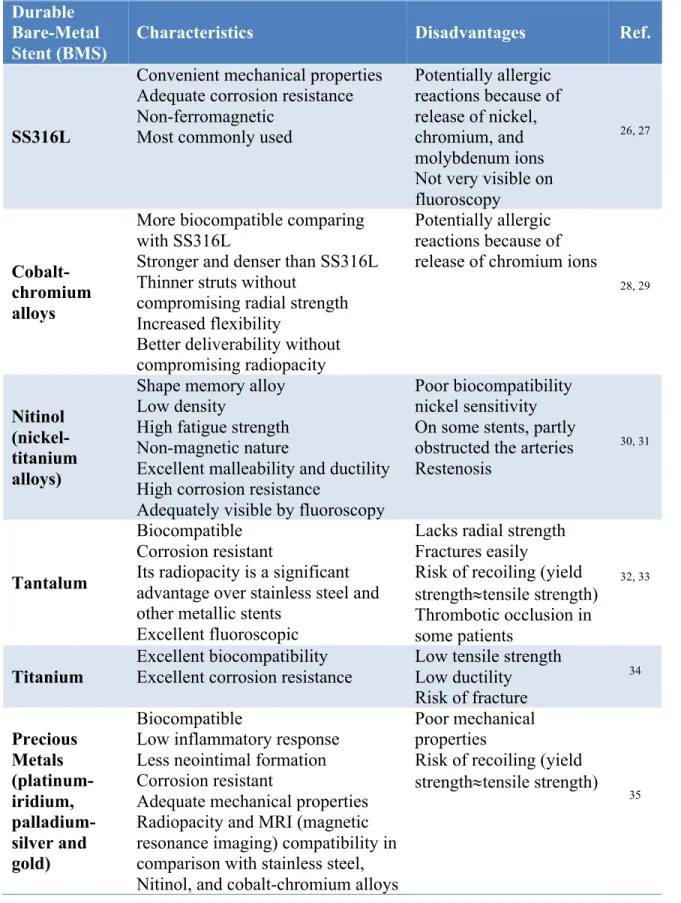
Current stent technology is based on the use of permanent implants made of corrosion resistant materials such as stainless steel 316L (SS316L), platinum-iridium alloy, tantalum, cobalt-chromium alloy, and titanium.25 In the following table, Table 1.2, a qualitative comparison between these kinds of stents are tabulated.
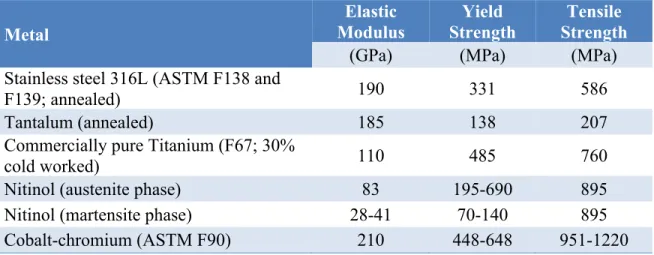
Among these materials, SS316L is by far the most used alloy due to its adequate mechanical properties and low cost. It is often considered as a standard reference material for mechanical properties, when developing new biomaterials for metallic stent applications. In this regard, mechanical properties of some common metals and alloys among them SS316L are presented in Table 1.3 for more comparison.
Table 1.2. Materials for durable bare stents, characteristics and disadvantages. Durable
Bare-Metal Stent (BMS)
Characteristics Disadvantages Ref.
SS316L
Convenient mechanical properties Adequate corrosion resistance Non-ferromagnetic
Most commonly used
Potentially allergic reactions because of release of nickel, chromium, and molybdenum ions Not very visible on fluoroscopy
26, 27
Cobalt-chromium alloys
More biocompatible comparing with SS316L
Stronger and denser than SS316L Thinner struts without
compromising radial strength Increased flexibility
Better deliverability without compromising radiopacity
Potentially allergic reactions because of release of chromium ions
28, 29
Nitinol (nickel-titanium alloys)
Shape memory alloy Low density
High fatigue strength Non-magnetic nature
Excellent malleability and ductility High corrosion resistance
Adequately visible by fluoroscopy
Poor biocompatibility nickel sensitivity On some stents, partly obstructed the arteries Restenosis
30, 31
Tantalum
Biocompatible Corrosion resistant
Its radiopacity is a significant advantage over stainless steel and other metallic stents
Excellent fluoroscopic
Lacks radial strength Fractures easily
Risk of recoiling (yield strength»tensile strength) Thrombotic occlusion in some patients 32, 33 Titanium Excellent biocompatibility Excellent corrosion resistance
Low tensile strength Low ductility Risk of fracture 34 Precious Metals (platinum-iridium, palladium-silver and gold) Biocompatible
Low inflammatory response Less neointimal formation Corrosion resistant
Adequate mechanical properties Radiopacity and MRI (magnetic resonance imaging) compatibility in comparison with stainless steel, Nitinol, and cobalt-chromium alloys
Poor mechanical properties
Risk of recoiling (yield strength»tensile strength)
Table 1.3. Mechanical properties of most common stent materials.36 Metal Elastic Modulus Yield Strength Tensile Strength
(GPa) (MPa) (MPa)
Stainless steel 316L (ASTM F138 and
F139; annealed) 190 331 586
Tantalum (annealed) 185 138 207
Commercially pure Titanium (F67; 30%
cold worked) 110 485 760
Nitinol (austenite phase) 83 195-690 895
Nitinol (martensite phase) 28-41 70-140 895
Cobalt-chromium (ASTM F90) 210 448-648 951-1220
As shown in Figure 1.8, in 2012, seven out of ten stents approved by the FDA/CE were made of SS316L. SS316L is still the most frequently-used material for manufacturing of permanent stents.37, 38 This is an austenitic, low carbon, non-magnetic, and face-centered
cubic (FCC) crystalline-structure stainless steel. The main element of this alloy is iron. Chromium is another main component that gives the steel its resistance to corrosion by creating a surface oxide layer mainly composed of chromium oxides and hydroxides.39 The chemical composition of this alloy is detailed in Table 1.4.
Figure 1.8. Repartition of FDA/CE approved stent materials in 2012 (reproduced from the reference).25
Table 1.4. Chemical composition of SS316L.40
Element C Mn Si Cr Ni
wt% <0.03 <2 <0.75 16-18 10-14
Element Mo P S N Fe
wt% 2-3 <0.045 <0.03 0.1 Bal. »66
The other permanent metallic stents, mentioned above, mostly are used for their improved radiopacity, superior radial strength, enhanced corrosion resistance, or better magnetic resonance imaging compatibility. Among these properties, improved radiopacity and superior radial strength are desired more since they allow the design of stents with smaller delivery profiles.25
There have been significant modifications in the material and design of bare-metal stent (BMS) over the last few years. Initial stents were usually made up of stainless steel, because it is biologically inert. In recent years, cobalt-chromium alloys have surpassed steel as the material of choice for stents, and allow newer stents to be designed with significantly thinner struts without compromising radial strength or corrosion resistance.19
1.4 Clinical Complications
It has been more than 30 years since stents, mainly made of SS316L, have reduced restenosis rates (10-30%) compared to simple balloon angioplasty (20-50%).41,42 However, several complications can occur due to their implementation. These complications can be divided into two main categories of short-term and long-term complications, such as restenosis, thrombosis, and inflammation for the short-term and release of potentially toxic ions, corrosion, and reduce of mechanical properties for the long-term.15,43,44
An iatrogenic injury to the vessel wall induced by stenting can promote proliferation of vascular smooth muscle cells primarily in the tunica intima (inner coat of vessels). This neointimal hyperplasia within or adjacent to stent leads to in stent restenosis (ISR), which is greater than a 50% reduction in the luminal diameter. ISR occurs in 30% of implanted
stents, within three months after their implantation. This finally results in partial or complete occlusion of the artery.45, 46
The causes of ISR are not yet entirely understood. However, allergy and hypersensitivity of patients to some metallic ions, which are present in stainless steel stents (e.g. nickel, chromium and molybdenum), can potentially trigger excessive intimal growth and develop restenosis.47, 48 The release of ions happens due to corrosion of stent when it comes in contact with body fluid that contains chloride ions, the most corrosive material for stainless steel.15
Among the released potentially toxic ions, nickel is known for being a allergenic and carcinogenic element and hexavalent chromium is a very strength oxidant and known for being a biologically active molecule and carcinogenic.43 Corrosion products are
accumulated in the tissues surrounding the implantation site and migrate through the blood vessels in the body to be accumulated or discarded.43, 49 This phenomenon declines the biocompatibility of the stent. Furthermore, it deteriorates the mechanical properties of the stent, which finally leads to its fracture.
In order to prevent ISR, some treatments have been developed, such as brachytherapy, drug coated balloon, oral pharmacotherapies, gene therapy, bypass surgery, and drug-eluting stent (DES). Among them DES is related to stents and have been considered as one of the procedures for stent manufacturing.41 DES types are especially treated stents that gradually release a special medication into the wall of the artery after they have been put into the blood vessel and has reduced the rate of ISR to 5%.19, 41 In early 2006, the use of DES in the U.S. stent procedures reached as high as 89%, but it decreased to between 60% and 70% the year after, according to Millennium data. Safety questions about the DES have triggered a steep decline in use. With the development of DES, however, the use is expected to be increased.22
BMS is preferred over DES in patients who cannot adhere to dual-antiplatelet therapy owing to a high risk of bleeding. The reason for this is because BMS is associated with a lower risk of stent thrombosis. However, in Norwegian Coronary Stent Trial (NORSTENT), the rate of stent thrombosis was 36% lower in the patients who received DES compared with those who received BMS. DES was associated with a robust
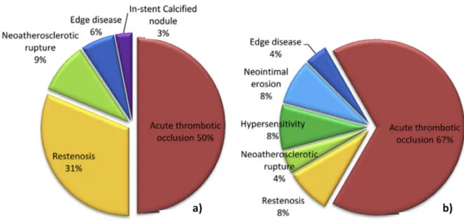
cost- reduction mainly due to a reduction in second revascularisations, myocardial infarctions, and stent thrombosis. There were no differences in overall survival that were predicted.50, 51 Another study revealed that at autopsy, in-stent chronic total occlusion was observed more frequently in BMS versus DES (11.7% vs. 5.9%). As exhibited in Figure 1.9, the most frequent cause was acute thrombotic occlusion (51% in BMS vs. 67% in DES), followed by restenosis (31% vs. 8%) and neoatherosclerotic rupture (9% vs. 4%).52, 53
One of the potential reasons that incurs in late restenosis is lack of endothelium regeneration after stenting procedures. Endothelial denudation is the primary injury that results after stent implantations, which may irritate or damage arterial walls and trigger neointimal hyperplasia of smooth muscle cells. Thus, treatments intend to avoid the hyperplasia and to stimulate the endothelialization process. Endothelialization regenerates the endothelium after stenting and also favours the formation of a layer of endothelial cells on the surface of the stent. In this process, the hypothesis is that the biomaterial surface will mimic the biological endothelium and will consequently create a naturally non-thrombogenic surface stable in the long term.41, 54, 55
Figure 1.9. The etiology of in stent chronic total occlusion, a) BMS and b) DES.52
Presently, in the fourth decade of PCI, in order to overcome the clinical complications, several approaches have been studied. These approaches include changes in stent design and metal composition, surface polymer coating, and anti-proliferative agents.56 Significant developments have occurred in the design of stent platforms, which leads to reduction in clinical complications. Variations in treatment are the result of differences in patient characteristics and clinical factors (e.g. anatomy), but previous studies have shown that physicians, hospital factors, and types of payment can contribute to treatment variation.42 The search for the ideal stent continues and interventional cardiologists in future will have a wide variety of stents available. These stents will enable the cardiologists to practice evidence-based personalized medicine, where the choice of the stent is based on genetic determinants, risk profile (for restenosis, thrombosis and bleeding), and lesion characteristics of individual patients.19
1.5 The LBB Project on Nano-Coatings for Stents
To weaken the clinical complications of SS316L stents, since 2002, the Laboratory for Biomaterials and Bioengineering of Université Laval (LBB) has been working on improving the surface properties of SS316L. In this context, Mantovani et al. proposed to deposit a polymeric coating with specific properties on the surface of the SS316L stents. Here, the coating should attain two ultimate goals: 1) to decrease the release of potentially toxic ions from SS316L and 2) to create an adequate surface for cell culture and endothelialization. The function of the polymer coating is to completely encapsulate and isolate the stent, to protect it from the biological environment, and to facilitate its integration into the human body for subsequent grafting of bioactive molecules.57
The coating is an ultra-thin film of fluorocarbons deposited by a plasma-based method. This polymer is similar to commercial Teflon and commonly known as Teflon-like coating and is termed CFx. To prepare the coating for cell culture, the CFx coating should be grafted
to bioactive molecules (e.g. phosphorylcholine). For this reason, amine groups are produced by plasma-based treatment on the surface of the CFx coating to link the bioactive