HAL Id: tel-01968037
https://pastel.archives-ouvertes.fr/tel-01968037
Submitted on 2 Jan 2019HAL is a multi-disciplinary open access archive for the deposit and dissemination of sci-entific research documents, whether they are pub-lished or not. The documents may come from teaching and research institutions in France or abroad, or from public or private research centers.
L’archive ouverte pluridisciplinaire HAL, est destinée au dépôt et à la diffusion de documents scientifiques de niveau recherche, publiés ou non, émanant des établissements d’enseignement et de recherche français ou étrangers, des laboratoires publics ou privés.
electrodes based on nanoparticles decorated carbon
nanotubes for Li-Ion batteries
Mariam Ezzedine
To cite this version:
Mariam Ezzedine. Fabrication of hierarchical hybrid nanostructured electrodes based on nanoparticles decorated carbon nanotubes for Li-Ion batteries. Other. Université Paris Saclay (COmUE), 2017. English. �NNT : 2017SACLX105�. �tel-01968037�
NNT : 2017SACLX105
Thèse de doctorat
de l'Université Paris-Saclay
préparée Ecole Polytechnique
Ecole doctorale n
◦573
INTERFACES : Approches Interdisciplinaires / Fondements,
Applications Et Innovations
par
Mme. Mariam Ezzedine
Fabrication d'électrodes nanostructurées hybrides hiérarchisées à base de
nanotubes de carbone décorés par des nanoparticules pour les batteries
Li-Ion
Thèse présentée et soutenue à l'Ecole Polytechnique, le 20.12.17. Composition du Jury :
M. Sylvain FRANGER (Président)
Professeur, Université Paris-Sud (ICMMO)
M. Lorenzo STIEVANO (Rapporteur)
Professeur, Université de Montpellier (ICGM)
Mme. Katia GUERIN-ARAUJO DA SILVA (Rapportrice)
Maitre de Conférences, Université Clermont Auvergne (ICCF)
M. Jean-Pierre PEREIRA-RAMOS (Examinateur)
Directeur de Recherche CNRS, Université Paris-Est (ICMPE)
M. Costel-Sorin Cojocaru (Directeur de thèse)
Directeur de Recherche CNRS, Ecole Polytechnique (LPICM)
Mme. Ileana FLOREA (Co-encadrante)
Trois ans d´ej`a, me voil`a finalement arriv´ee au bout de mon aventure. Ce travail de th`ese `
a la fois stimulant et pesant est accompli. Trois ann´ees formidables qui sont pass´ees `a la vitesse de la lumi`ere au sein de LPICM.
Au premier chef, je remercie la ”Chaire et Energie” qui a financ´e ma th`ese. Je remercie ´
egalement les membres de mon jury: Lorenzo Stievano, Katia Guerin-Araujo Da Silva, Jean-Pierre Pereira-Ramos et Sylvain Franger pour avoir accept´e de juger ce travail. Je voudrais exprimer ma plus profonde gratitude, ma gratitude incommensurable `a mon directeur de th`ese Costel-Sorin Cojocaru. Merci d’abord d’avoir cru en moi, de m’avoir soutenue dans les moments les plus difficiles. Ces moments de doute o`u tout espoir `a mes yeux ´etait vain. Merci d’avoir r´ep´et´e sans cesse ces mots magiques: ”mais non il ne faut pas perdre espoir tu vas y arriver”. Merci pour ta disponibilit´e, pour m’avoir permis lors des moments difficiles de te poser maintes questions. Merci d’avoir pris le temps de discuter avec moi. Merci pour les r´eparations et les bricoles qui m’ont permis d’avancer dans la d´ecoration de mes beaux nanotubes de carbone. Merci aussi pour ces discussions pass´ees dans la salle Fenix. Enfin, mille merci pour tes conseils et surtout pour ta grande patience. Les mots me manquent pour t’exprimer toute la gratitude que je ressens. Merci !
Ileana Florea ma super encadrante, sache aussi qu’un simple merci n’est point suffisant pour te remercier de ta pr´esence et de ton aide qui sont tr`es pr´ecieux `a mes yeux. Toutefois, merci pour tous les beaux clich´es de microscopie et les heures que tu as pass´ees `a Nanomax pour moi. Je te suis ´eternellement reconnaissante pour avoir ´et´e `a mes cˆot´es, pour m’avoir ´epaul´ee, conseill´ee, soutenue et pour m’avoir surtout remont´e le moral. Chacun de ces moments pass´es dans ton bureau et `a Nanomax sont inoubliables. Je pense `a nos discussions de tout et rien, `a mes larmes vers´ees et `a tes mots doux qui me r´econcilie avec mon travail. Ma th`ese n’aurait jamais ´et´e pareil sans TOI !!
Je tiens `a remercier ´egalement mon ´equipe NanoMade : L´eo, Garry, Didier, Marc, Fatima, Salom´e, Leandro et Mihai. Salom´e, merci d’avoir ´et´e pr´esente quand j’avais besoin de toi et surtout pendant les derniers jours de r´edaction sur Latex (beaucoup de panique). Leandro merci de m’avoir avis´e `a l’´electrod´eposition. Mihai, ”mon coll`egue de batterie”, merci pour toutes nos discussions et surtout merci pour ta patience, et pour m’avoir ´eclair´e avec tes r´eponses `a mes questions avant ma soutenance.
Fatima Jardali ”babe” ma tr`es ch`ere amie et ma tr`es ch`ere coll`egue de bureau. Merci pour ta compagnie pendant ces trois ans. Trois ans de joie, de rires, de larmes et surtout de stress. Je suis reconnaissante de t’avoir crois´e et surtout d’avoir partag´e un temps et un espace avec toi. Je suis reconnaissante `a cette amiti´e qui est n´ee entre nous.
Je tiens `a remercier Sandrine Tusseau-Nenez pour m’avoir form´e sur la DRX et pour les heures que tu as pass´ees en ma compagnie devant la machine afin de comprendre son
obstination `a ne pas d´emarrer.
Je remercie toute l’´equipe administrative, ainsi que l’´equipe de support du LPICM. Je finis ces remerciements en pensant `a ma famille: mon p`ere, ma m`ere et mon fr`ere. Merci de m’avoir soutenue pendant 8 ans d’´etudes, et merci de m’avoir encourag´ee `a viser haut.
Je suis ´emue et triste `a l’id´ee de quitter ce labo un jour. Merci pour m’avoir accord´e encore un an pour travailler parmi vous. D´esormais adviendra le jour o`u je dois me s´eparer de vous, ce jour fatidique qui m’obligera `a quitter le nid m’attriste d´ej`a.
Acknowledgements i
List of Figures vii
List of Tables xi
General Introduction 1
1 Introduction 5
1.1 A brief history . . . 5
1.2 Lithium-ion battery . . . 6
1.2.1 Why a Lithium-ion battery?. . . 7
1.2.2 Mechanisms of charging and discharging . . . 7
1.2.3 Electrode materials. . . 10
1.2.3.1 Cathode materials . . . 11
1.2.3.2 Anode materials . . . 13
1.2.3.3 Electrolyte . . . 16
1.2.3.4 Current collectors . . . 19
1.3 Advantages of nanomaterials structure . . . 20
1.4 Ideal material . . . 21
2 Carbon nanotubes acting as nanostructured current collectors 23 2.1 Carbon allotropes. . . 23 2.2 Carbon nanotubes . . . 25 2.3 Physical properties . . . 26 2.3.1 Electronic properties . . . 26 2.3.2 Mechanical properties . . . 27 2.3.3 Thermal properties . . . 27 2.3.4 Electrochemical properties. . . 27
2.4 Carbon nanotubes based devices . . . 28
2.4.1 CNT-based LIBs . . . 29
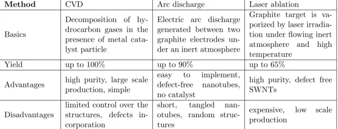
2.5 Carbon nanotubes synthesis . . . 31
2.5.1 Chemical Vapor Deposition method . . . 33
2.6 Vertically Aligned Carbon Nanotubes . . . 36
2.6.1 Synthesis of vertically aligned carbon nanotubes . . . 36
2.6.2 Experimental setup. . . 36
2.6.3 Synthesis of VACNTs-based nanostructured current collector . . . 38 iii
2.6.4 Electron microscopy: VACNTs morphological and structural
char-acterization . . . 42
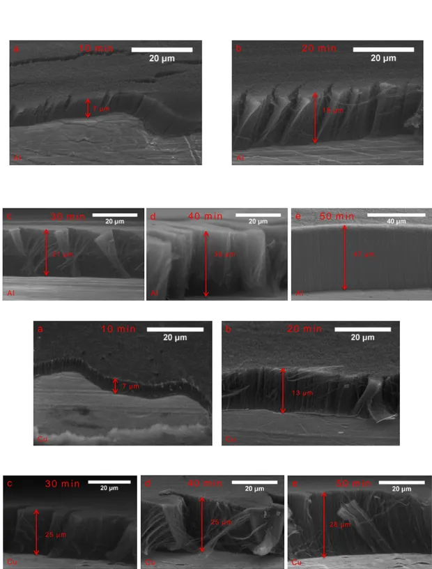
2.6.5 Effect of the growth time on the length of the VACNTs . . . 43
2.7 Conclusion . . . 46
3 Cathode nano-fabrication 47 3.1 Concept of a lithium-sulfur battery . . . 48
3.1.1 Challenges in a Li/S battery . . . 51
3.1.2 Cathodes for Li/S batteries . . . 53
3.1.2.1 Sulfur-carbon composites . . . 54
3.1.2.2 Sulfur-polymer composites . . . 55
3.1.2.3 Alternative composites . . . 56
3.1.3 Li2S acting as the cathode material. . . 56
3.2 Synthesis methods for the cathode materials . . . 57
3.2.1 Electrodepositon process. . . 57
3.2.1.1 Experimental setup for the electrodeposition of sulfur . . 59
3.2.1.2 SEM and EDS characterizations of S NPs obtained by electrodeposition . . . 60
3.2.2 PVD technique . . . 60
3.2.2.1 Sulfur Evaporation. . . 62
3.2.2.2 SEM characterization of S@VACNT obtained by evapo-ration . . . 62
3.2.2.3 GIXRD characterization of S@VACNT obtained by evap-oration . . . 62
3.2.2.4 Cell assembly. . . 64
3.2.2.5 Electrochemical testing of S@VACNT nanostructured elec-trode . . . 66
3.2.3 Alumina coating of S@VACNT nanostructured cathode . . . 68
3.2.3.1 Evaporation of alumina barrier on S@VACNT cathode . 70 3.2.3.2 Electrochemical testing of Al2O3@S@VACNT nanostruc-tured electrode . . . 70
3.2.4 Polyaniline coating of S@VACNT nanostructured cathode . . . 71
3.2.4.1 Electrodeposition of polyaniline barrier on S@VACNT cathode . . . 72
3.2.4.2 SEM characterization of PANI@S@VACNT . . . 73
3.2.4.3 GIXRD characterization of PANI@S@VACNT . . . 73
3.2.4.4 Electrochemical testing of PANI@S@VACNT nanostruc-tured electrode . . . 75
3.2.5 Comparison of the performance of the PANI@S@VACNTs and the Al2O3@S@VACNTs nanostructured electrodes . . . 76
3.3 Nickel nanoparticles: an alternative material for the nanostructured cath-ode . . . 78
3.3.1 Experimental set-up . . . 78
3.3.2 Morphological and structural characterization of the Ni@VACNTs assembly . . . 78
3.3.3 Electrochemical testing of NiO@VACNTs nanostructured electrode 83 3.4 Conclusion . . . 84
4 Anode nano-fabrication 87
4.1 Advantages and disadvantages of silicon as active material . . . 88
4.2 Mechanisms of lithiation and delithiation of silicon . . . 91
4.3 Nanostructured silicon anode . . . 93
4.4 Electrodeposition of Silicon . . . 97
4.4.1 Cycling voltammetry technique . . . 99
4.4.1.1 SEM and TEM characterizations of Si NPs obtained by CV . . . 100
4.4.1.2 Electrochemical performance . . . 101
4.4.2 Pulse electrodeposition technique . . . 102
4.4.2.1 SEM characterization of Si NPs obtained by PED . . . . 103
4.4.2.2 Electrochemical performance . . . 103
4.4.3 Comparison of the performance of the CV and PED techniques . . 105
4.5 Chemical Vapor Deposition technique . . . 106
4.5.1 First approach . . . 106
4.5.1.1 SEM and TEM characterizations of Si NPs obtained by CVD . . . 107
4.5.1.2 Electrochemical performance . . . 108
4.5.1.3 Rate capability . . . 113
4.5.2 Second approach . . . 114
4.5.2.1 SEM and electrochemical characterizations of Si NPs ob-tained by CVD . . . 115
4.6 Conclusion . . . 118
5 Towards a full battery based on nanostructured electrodes 119 5.1 Motivation . . . 119
5.2 Half-cell test of Si@VACNT anode . . . 119
5.3 Lithiation of Al2O3@S@VACNT . . . 121
5.4 Towards the full-cell . . . 121
General Conclusion and Perspectives 125 A Appendix 131 A.1 Scanning electron Microscopy . . . 131
A.2 Transmission electron Microscopy . . . 131
B Appendix 135 B.1 X-ray diffraction . . . 135 C Appendix 139 C.1 Cyclic Voltammetry . . . 139 C.2 Galvanostatic cycling. . . 139 R´esum´e de la th`ese 141
1 World energy consumption of the year 1990-2040. . . 2
1.1 Specific energy vs. specific power for different types of rechargeable
bat-teries. . . 7
1.2 Schematic of a Li-ion battery operating during discharge and charge
pro-cesses. . . 8
1.3 Schematic illustration of electrode materials and their electrochemical
performances in the current and the future Li-ion technologies. . . 10
1.4 Crystal structure of layered LiMO2, Spinel LiM2O4 and Olivine LiMPO4 . 11
1.5 Chemical formulae of the main carbonate solvents used in the electrolyte
in Li-ion batteries. . . 17
2.1 Structure of different allotropes of carbon: (a) Diamond, (b) Graphite,
(c) C60 ( Buckminsterfullerene or buckyball), (d) Amorphous carbon, (e)
Single-wall carbon nanotube or buckytube. . . 24
2.2 Schematic representation of a SWCNT and a MWCNT. . . 26
2.3 Global CNT request by different fields of application.. . . 29
2.4 Growth mechanisms for CNTs: (a) tip-growth mode, (b) base-growth mode. 34
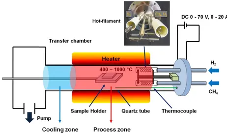
2.5 Schematic design of the hot filament chemical vapor deposition system. . 37
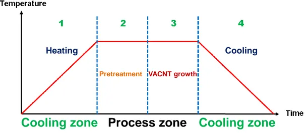
2.6 General procedure of the synthesis of VACNTs by dHF-CVD approach. . 38
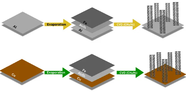
2.7 Schematical representation of the main stages of the synthesis of VACNT
on Al and Cu substrates. . . 39
2.8 SEM and TEM observations on FIB cross-section lamellas of Al2O3@Fe
layers assembly deposited onto the Al substrate before (top) and after
annealing (bottom) the sample. . . 40
2.9 SEM image of random CNTs synthesized on Al and Cu substrates during
30 minutes with starting Fe catalyst layer less of 10 nm thick. . . 41
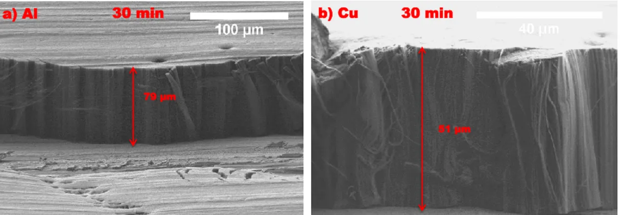
2.10 Cross-sectional SEM images of VACNTs carpets grown on Al and Cu
substrates during 30 minutes. . . 43
2.11 TEM observations on the CNTs synthesized on Al (top) and Cu (bottom)
substrates.. . . 44
2.12 Cross-sectional SEM images of VACNTs carpets grown on Al and Cu
substrates at different growth times. . . 45
3.1 Schematic illustration presenting the hybrid nanostructured cathode
nano-fabrication concept.. . . 48
3.2 Typical voltage vs. capacity plot for a Li/S cell explaining the evolution
of the polysulphide species. . . 50
3.3 Typical discharge and charge voltage profile at the first cycle of a Li/S cell. 51
3.4 Applied pulse for the electrodeposition process. . . 58
3.5 Schematic representation of the experimental set-up used for the
elec-trodeposition process. . . 59
3.6 SEM images of S NPs cathode on VACNT carpets. . . 61
3.7 EDS analysis of S NPs synthesized from an electrodeposition process. . . 61
3.8 The PVD experimental setup used for sulfur evaporation. . . 63
3.9 Cross-sectional SEM images of S@VACNT obtained after evaporation of S. 63
3.10 A zoom of the GIXRD pattern of CNTs around 24◦. . . 64
3.11 GIXRD patterns of S@VACNT.. . . 65
3.12 A schematic representation of a coin-cell. . . 65
3.13 Voltage capacity curves of S@VACNT at C/20 between 1.5-2.8 V vs Li/Li+. 68
3.14 Cyclic behavior of S@VACNT nanostructured electrode with Coulombic
efficiency at C/20 rate between 1.5-2.8V vs Li/Li+. . . 69
3.15 a) Lithiation/ delithiation profiles and b) the differential capacity plot
of the Al2O3@S@VACNT electrode obtained after one, two, ten, twenty,
thirty, and forty cycles between 1.7-2.45 V vs Li/ Li+ at a C/20 rate.. . . 72
3.16 PANI electrodeposition by CV technique on S@VACNT electrode. . . 73
3.17 Sectional view SEM image of PANI@S@VACNT. . . 74
3.18 GIXRD patterns of PANI@S@VACNT. . . 74
3.19 a) Lithiation/ delithiation profiles and b) the differential capacity plot of the PANI@S@VACNT electrode obtained after one, two, ten, twenty,
thirty, and forty cycles between 1.6-2.5 V vs Li/ Li+ at a C/20 rate. . . . 76
3.20 Comparison of the cycling performance of PANI@S@VACNTs and Al2O3@S@VACNTs
nanostructured electrodes at a C/20 rate. . . 77
3.21 SEM images of the Ni@VACNTs where Ni NPs were deposited by PED. . 79
3.22 TEM analyses of the Ni@VACNTs where Ni NPs were deposited by PED. 80
3.23 SEM and TEM images on a FIB cross-section lamella prepared on a
Ni@VACNTs assembly.. . . 81
3.24 HR-TEM and elemental maps recorded using the EFTEM imaging mode of the electron microscope evidencing the NiO structure for all the Ni NPs
deposited using the PED process. . . 81
3.25 HR-TEM and STEM-HAADF analyses of the different NiO NPs after
annealing at 500◦C for 10h under water vapor atmosphere. . . 82
3.26 XRD patterns of Ni@VACNT. . . 83
3.27 Electrochemical performance of the NiO@VACNT nanostructured
elec-trode obtained after fifty cycles between 2.5-3.4V vs Li/ Li+ at a C/20
rate. . . 84
4.1 Schematic illustration showing the nano-fabrication of the hybrid
nanos-tructured anode. . . 88
4.2 Volume variations of different compositions of LixSi alloy with respect to
silicon. . . 89
4.3 Si electrode failure mechanisms: (a) Anode material pulverization. (b)
Morphology and volume changes of whole Si electrode. (c) Continuous
4.4 Si electrochemical lithiation and delithiation curve at ambient
tempera-ture and high temperatempera-ture. Black line: theoretical voltage curve at 450◦C.
Red and green line: lithiation and delithiation of crystalline Si at ambient
temperature, respectively. . . 91
4.5 Voltage curve of a crystalline Si electrode cycled in a way to illustrate the
electrochemical conversion of crystalline Si to amorphous Si, amorphous
Si to crystalline Li15Si4, and Li15Si4 back to amorphous Si. . . 92
4.6 First cycle galvanostatic curves for single-crystalline Si NWs, amorphous
Si NWs, and polycrystalline Si NWs. . . 94
4.7 Schematic of SiNWs electrode assembled on the current collector. . . 95
4.8 The set-up of the fabricated cell used for the electrodeposition of silicon. . 99
4.9 Cyclic voltammogram carried out on a VACNTs carpet at room
temper-ature and Si (IV) concentration of 1 M. . . 100
4.10 SEM and TEM images of the Si@VACNTs deposited by CV. . . 101
4.11 Galvanostatic lithium-insertion/ extraction curves of Si@VACNTs
elec-trodes between 0.02 and 1.5 V at a rate of C/3. . . 102
4.12 SEM images of the Si@VACNTs where Si NPs were deposited by PED. . 104
4.13 Galvanostatic lithium-insertion/ extraction curves of Si@VACNTs
elec-trodes between 0.02 and 1.5 V at a rate of C/20. . . 105
4.14 Comparison of the cycling performance of Si@VACNTs electrodes ob-tained by CV and PED techniques between 0.02 and 1.5 V at a rate of
C/20. . . 106
4.15 SEM images of Si@VACNTs hybrid structure obtained by CVD. . . 108
4.16 TEM analysis of the Si@VACNTs hybrid structure obtained by CVD. . . 109
4.17 Voltage vs. capacity plot and the differential capacity with the cell
po-tential plot of lighter loaded Si@VACNTs nanostructured electrode. . . . 111
4.18 Voltage vs. capacity plot and the differential capacity with the cell
po-tential plot of heavily loaded Si@VACNTs nanostructured electrode. . . . 111
4.19 Lithiation/ delithiation capacities and Coulombic efficiency of Si@VACNT
electrode during 400 cycles. . . 112
4.20 a) Rate capability plot of the Si@VACNT nanostructured anode obtained
at different C rates between 0.02-2 V vs Li/ Li+. b) and c) Plots of
dif-ferential capacity versus cell potential of the hybrid Si@VACNT
nanos-tructure anode. . . 114
4.21 SEM images of Si@VACNT anode with different lengths of VACNT. . . . 116
4.22 a) Comparison of the lithiation areal capacity of our electrodes in func-tion of the deposited silicon mass. b) Comparison of the lithiafunc-tion areal capacity of the silicon nanotrees, the silicon composite based electrodes
and the commercial graphite . . . 117
5.1 Lithiation/ delithiation capacities and Coulombic efficiency of Si@VACNT
electrode in the same electrolyte employed for sulfur electrodes. . . 120
5.2 Charge/ discharge capacities of the full cell. . . 123
A.1 A simplistic representation of a transmission electron microscope and the various signals produced by the possible interactions between electrons
and the material. . . 133
1.1 Characteristics and performance of commonly used rechargeable batteries. 6
1.2 Comparison of the theoretical specific capacity, charge density, volume
change and onset potential of various anode materials. . . 15
2.1 An overview on the most common CNTs synthesis methods and their
advantages and disadvantges. . . 33
Most of the energy used on earth is originated from the sun. Primary energy sources take many forms, including nuclear energy and fossil energy such as coal, oil and natural gas. Other than these, energy resources also include renewable sources e.g., wind, solar, geothermal and hydropower. These sources are then converted to electricity to serve the humans. The constantly improving standards of living of the world’s population heavily rely on energy consumption, which is increasing rapidly in proportion to the growth in the economy as well as in the global population. When considering the increasing population of our world, we could imagine extraordinary large energy consumption in the near future. According to recent studies, the annual worldwide energy consumption is currently estimated to be 13 trillion watts.[1] The world energy consumption will grow by 48% between 2012 and 2040. Most of this growth will come from emerging countries, such as China and India. Out of all energy resources, fossil fuels (oil, coal, and natural gas) will still account for more than three-quarters of the world energy consumption through 2040 (see figure 1). [2] However, most of the non-renewable fossil fuel energy will be exhausted within the next 200 years.[3] Additionally, greenhouse gas emission is rapidly becoming a serious problem of environmental pollution. The conservation of natural resources and reduction of greenhouse gases are considered as major challenges of the global economies and governments.[4] As the world population keeps rising and our lifestyle demands more resources, humankind is forced to move towards sustainable and renewable resources. In the recent years, various clean energies have been explored as energy alternatives, such as solar and wind power.[5] These clean renewable energy resources are highly time or region-dependent. It is essential, therefore, to develop effective energy storage media in order to use such intermittent energy sources in an efficient way.[6] Great efforts have been made in searching for viable solutions, including Electrical Energy Storage (EES), load shifting through demand management, interconnection with external grids, etc. Amongst all the possible solutions, EES has been recognized as one of the most promising approaches. EES technology refers to the process of converting energy from one form (mainly electrical energy) to a storable form and reserving it in various mediums. Thereafter, the stored energy can be converted
Figure 1: World energy consumption of the year 1990-2040.
[2]
back into electrical energy when needed.[7]
Among the different EES technologies, lithium-ion batteries (LIBs) is one of the most promising candidates for energy storage due to their high operating voltage, high energy and high power density.[8] Current Li-ion batteries do not yet meet the expectation of tomorrow0s energy storage system. New batteries with significantly higher energy density and long cycle life would have significant benefits. The enhancement of energy density of LIBs can be achieved by developing either high capacity cathode and anode materials, or high voltage cathode materials. The development of new electrode materials with improved electrochemical performance is highly required. In the early 20th century, the discovery of the allotropes of carbon (fullerene C60 and carbon nanotubes) gave
a stimulus to the development of nanomaterials and made researchers ready to explore more avidly the potential use of these materials, including Li-ion battery applications.[9] From this perspective, the choice of electrode materials will play an important role in the next-generation battery design. Electric vehicles manufacturers and renewable energy storage facilities require an increase in both energy and power density of current batteries technology. This is where nanomaterials are expected to provide a sizeable increment in performance owing to their unique properties. In fact, nanomaterials are potentially able to store more charge than conventional micron-sized materials because they offer additional lithium storage sites. Also, nanosized materials can accommodate with lithium ions in much shorter time than bulk structures, making quick charge and discharge possible, thus providing the tremendous power density necessary to accelerate a car and to store energy under peak conditions of wind and solar energy generation.[10]
Outline of the thesis
Sulfur and silicon are both attractive electrode materials for next generation recharge-able lithium ions batteries because of their abundance, high theoretical capacity, and low cost. This thesis is mainly focused on the fabrication of nanostructured sulfur cath-ode and nanostructured silicon ancath-ode, and then the assembly of the full cell based on nanostructured electrodes for LIBs with improved energy and power densities, and cycle life.
The manuscript begins with a general introduction, which gives an overview on the importance of the electrical energy storage in the context of the world energy demands, and is composed of five Chapters.
In the first Chapter, an introduction to generalities a LIB system and a brief history of the LIB development are given. The operating principles of LIBs are also explained. Summaries on the cathode and anode materials used in LIBs system are presented. Finally, the challenges that are existing nowadays in LIBs and the solutions that are offered by different nanomaterials are reviewed. The second Chapter offers an overview on carbon nanotubes and their fabrication methods and presents the synthesis method of vertically aligned carbon nanotubes on two different commercial substrates, allowing for the design of the nanostructured current collector. The third Chapter is devoted to the sulfur cathode electrode. It begins by a general background on Li/S batteries. Then, it describes the experimental work for the nanofabrication of the sulfur electrode based on carbon nanotube carpets and proposes further improvements of the sulfur electrode by coating it with two different materials. The corresponding results obtained for the electrochemical testing are reviewed. The fourth Chapter is focused on the silicon anode electrode. It covers the literature background of silicon as anode material for LIBs. To tackle the problems of silicon anode, such as poor cyclability and early capacity fading due to significant volume variation during lithiation/ delithiation processes, nanostruc-turation of the silicon anode based on silicon nanoparticles-decorated-carbon-nanotubes was fabricated by two different techniques. The detailed experimental procedures and the electrochemical performances are also presented. The fifth Chapter is devoted to a metallic-lithium-free battery. The two electrodes based on hybrid nanostructured cathode (S@VACNTs) and anode (Si@VACNTs) electrodes were assembled in order to obtain the full cell. A first trial and a proof of our concept was demonstrated.
Finally, a general conclusion summarizes the overall work and provides some perspectives for further research work related to such nanostructured electrodes.
Introduction
1.1
A brief history
A battery is a system that converts chemical energy into electrical energy. The first battery was created in 1800 by Alessandro Volta. It consisted of a column made with superimposed discs of three different substances: two metals, such as Zn and Cu, and pieces of wet cardboard soaked in salt water, placed in the same order. When connecting the two metal discs at the extremities of the column, the apparatus produced a steady electric current.[11] Batteries can be broadly divided into two categories; primary (or disposable) batteries and secondary (or rechargeable) batteries, depending on whether or not they can be charged. The primary batteries are not rechargeable and their electrochemical reaction is irreversible, while the secondary batteries are built to be charged and discharged for multiple cycles, i.e the electrochemical reaction is reversible. In primary batteries category, one can find the “Daniel cell”battery developed in 1820 followed by “Leclanch´e”battery (Zn/MnO2) in 1866. In 1859, Gaston Plant´e invented
the lead-acid battery: the first rechargeable battery. These batteries are still widely available today, equipping almost all of our thermal vehicles. Their main advantage is their low cost, but they posses low specific energy and power density. To increase the energy density, new types of secondary batteries have started to appear gradually during the 20th century. Nickel-cadmium (Ni-Cd) technology was proposed in 1900 by Waldmar Jungner. However, the hazardous nature of cadmium has raised major environmental problems leading to the development, starting in 1975, of nickel-metal hydrides (Ni-MH) systems which are less toxic and have a higher energy density.
The discovery of reversible lithium intercalation in titanium disulfide (TiS2) [12, 13]
and molybdenum disulphide (MoS2) [14] led to the development of rechargeable lithium
batteries in the 1970s. However, various safety problems have been encountered on 5
Table 1.1: Characteristics and performance of commonly used rechargeable batteries.
Battery type Lead-Acid Ni-Cd Ni-MH Li-ion
Voltage (V) 2.0 1.2 1.2 4.1
Specific energy (Wh/kg) 35 35 75 150
Energy density (Wh/L) 70 100 240 400
Cycle life 200-250 400-500 400-500 >1000
the first batteries which used a lithium metal electrode and a liquid electrolyte. Upon continuous reversible charge and discharge cycles, dendritic Li forms on lithium surfaces due to uneven Li plating and hence causing short circuits and battery failure; hence, metallic lithium is not widely used as anode material in rechargeable batteries. Two solutions have been proposed to overcome these problems. The first one was proposed by Armand et al [15] and consists in replacing the liquid electrolyte with a solid electrolyte made of polymers, which is then referred to as a Li-polymer battery. The second was proposed in 1980 by D.W. Murphy [16] and B. Scrosati [17] and consists in replacing the metallic lithium electrode with a host material which receives lithium reversibly. Later in 1991, LIBs were commercialized and emerged for the first time by Sony Corporation. Since then, LIBs have gained a huge interest and a rapid development and advancement both in academic research and in business market.
1.2
Lithium-ion battery
Among a wide range of energy storage technologies, lithium-ion batteries, commonly abbreviated as LIBs or Li-ion batteries, have gained considerable interest because of their high specific energy, good cycle life, good power performance and lighter weight [18] compared to other battery systems (see figure1.1and Table1.1).[19] Owing to their great characteristics, LIBs have been first widely applied in portable electronic devices. According to the recent market investigations, the share of worldwide sales for Ni-Cd and Ni-MH batteries are 23 and 14%, respectively. However, Li-ion portable batteries take up to 63% of the battery market.[20] Recently, Li-ion batteries are being intensively pursued in large-scale transportation applications especially in hybrid electric vehicles (HEV), plug in hybrid electric vehicles (PHEV) and electric vehicles (EV). LIBs are starting to be seriously considered as a solution to the intermittency problem in renewable energies, e.g. solar and wind.[21] The energy and power density of LIBs are generally higher than those of other rechargeable batteries such as lead acid, Ni-Cd or Ni-MH batteries (see Table1.1).
Figure 1.1: Specific energy vs. specific power for different types of recharge-able batteries.[22]
1.2.1 Why a Lithium-ion battery?
Lithium-ion systems are appealing for their use in batteries because of the lithium par-ticularities. Lithium, the third element in the periodic table, is the most electropositive element (-3.04V at 25◦C vs standard hydrogen electrode (SHE)), generating a large potential difference when paired with a positive electrode material (see Table1.1) In ad-dition, due to its small radius, 78 ppm, Li+ ion is the lightest amongst all metallic ions. This characteristic gives it a great mobility during the intercalation/ deintercalation processes in a material and during the migration inside the electrolyte. Additionally, Li+ ion can easily penetrate within the vacant sites of many crystalline meshes to form a wide variety of compounds. Finally, and thanks to its low density (0.53 g cm−3), LIBs present higher gravimetric and volumetric energy densities than other battery systems (see figure1.1).[19]
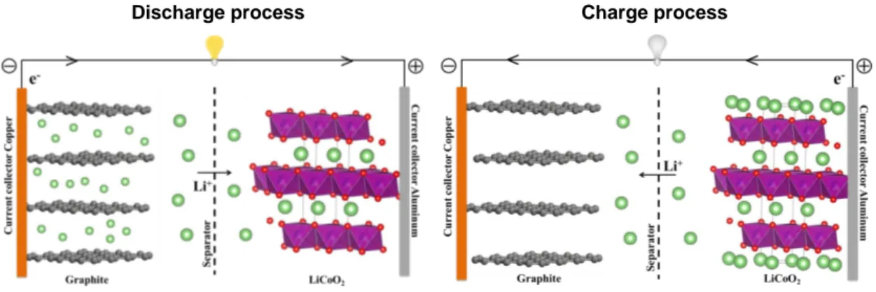
1.2.2 Mechanisms of charging and discharging
A Li-ion system is composed of an electrochemical cell including a positive electrode, commonly named cathode and a negative electrode called anode separated by an elec-trolyte which allows a good ion transfer and a poor electron conductivity. The cathode materials are intercalation compounds of Li+ion often made from a lithium metal oxide whilst the anode materials, most of the time, consist of graphitic carbon. The elec-trolyte is an organic solvent composed of a lithium salt, usually LiPF6, dissolved in a
is a porous polymer is placed between the positive and the negative electrodes to pre-vent their contact, but still allowing the transport of Li+ions. Throughout the working process of the battery, redox reactions take place inside the cell. During the discharging process, the Li+ ions flow spontaneously from the anode, through the electrolyte, and embeds into the cathode. This generates an electron flow from the negative to the pos-itive electrode through the external circuit. During the charging process, the ionic and electronic processes are reversed, i.e., the ions migrate from the positive to the negative electrode. These two processes are referred as deintercalation and intercalation mech-anisms of lithium. The lithium-ion battery is also known as a ”rocking-chair battery”, since Li+ions migrate back and forth between the two electrodes during cycling without being reduced to a metallic form (see figure1.2).
Discharge process Charge process
Figure 1.2: Schematic of a Li-ion battery operating during discharge and charge processes. Left: discharging process; Right: charging process.
For example, in a commercial Li-ion battery composed of graphite (anode) and LiCoO2
(cathode), the reactions that take place during the discharging and charging processes on the anode and cathode are the following:
At the anode: LixC6
discharge
charge C6+ x e
− + x Li+
At the cathode: Li1−xCoO2 + x e− + x Li+
discharge
charge LiCoO2
Overall reaction: Li1−xCoO2 + LixC6
discharge
charge LiCoO2 + C6
The performance of LIBs crucially depends on the nature and the characteristics (mor-phology, structure and composition) of the electrode material considered for both elec-trodes. The main parameters generally used to evaluate the quality of the electrode material are the following:
• Cell potential (V): is the potential difference between the positive and the negative electrode which, in turn, depends on the composition of the electrodes. A larger difference of the standard potential between cathode and anode is desired for a full cell, since the output energy is the product of voltage and capacity. However, this potential difference has to be within the potential window of the electrolyte that is in use, in order to prevent electrolyte decomposition.
• Cell capacity: is the quantity of charge that a battery can deliver to a given current. It is expressed in Ampere-hour (Ah). The performance of each electrode can be estimated by its specific capacity, expressed in Ah kg−1, which corresponds to the ratio of the capacity to the mass of the active material. The theoretical specific capacity of an electrode depends on the number of electrons that can be exchanged during the same charge or discharge process per mole of active material. It can be calculated using the following equation:
capacitytheo=
F × ne−
3600 × M (1.1)
Where ne− is the number of electrons transferred during the electrochemical re-actions, F is the Faraday constant (96,485.33 C mol−1) and M is the molecular weight of the active material (g mol−1).
• Coulombic efficiency: is the ratio of number of charges that enter the battery during charging (charge capacity) to the number of charges that can be extracted during discharging (discharge capacity).
• Gravimetric and volumetric energy density: are the energy per unit weight (gravi-metric Wh Kg−1) or unit volume (volumetric Wh L−1).
Gravimetric energy density= (Specific capacity/ Kg) × Cell voltage Volumetric energy density= (Specific capacity/ L) × Cell voltage
• Power density: is the battery power that represents the speed at which the energy can be delivered to the load and it is expressed in (W/Kg or W/L) .
Power density= Energy density/ Time.
• Rate capability or (C-rate): is used to evaluate how fast Li+ ions can be
trans-ferred. For example, C/2 means a current allowing a full charge or discharge in 2 hours.
1.2.3 Electrode materials
As mentioned previously, the electrochemical performance of the LIBs is largely dictated by the choice of the electrode materials. In general, the electrode materials are a mixture of an active material, a conductive material and a binder cohered to the current collec-tor (typically copper foil for anode and respectively aluminium foil for cathode). The different electrode materials are classified according to their specific capacities and their electrochemical potentials. The materials with a potential higher than 2V are defined as a cathode material and those with a potential lower than 2V is defined as an anode material. In order to obtain a battery with a high energy density, the two electrode materials must have a high specific capacity and a large potential difference between them. For a high specific capacity, the quantity of Li+ ions inserted and extracted from the electrode materials must be large during the charge and the discharge processes. For obtaining a large potential difference, the negative electrodes must have a low reduction/ oxidation potential, typically as close as possible to that of the lithium, whereas the pos-itive electrodes must work at a high potential. The potentials and specific capacities of various electrode materials are summarized in figure 1.3.[20]
Si S
Figure 1.3: Schematic illustration of electrode materials and their electro-chemical performances in the current and the future Li-ion technologies.[20]
1.2.3.1 Cathode materials
There are several possible types or families of materials that can potentially be considered for the positive electrode of a Li-ion battery. The cathode materials can be divided into three major categories:
1. Layered transition metal materials (LiMO2)
2. Spinel materials (LiM2O4)
3. Olivine structured oxide materials (LiMPO4)
The schematic representation of their crystal structure is illustrated in figure1.4.[23]
Figure 1.4: Crystal structure of layered LiMO2 (left), Spinel LiM2O4
(mid-dle) and Olivine LiMPO4 (right)[23]
.
• Layered transition metal materials (LiMO2)
The discovery of lithium cobalt oxide LiCoO2 (LCO) was attributed to
Goode-nough’s team in 1980.[24] It was the first cathode material to be commercialized by Sony Corporation in 1991 and is still used in many commercial LIBs.[25] The structure of LCO consists of alternating cobalt dioxide CoO2 and Li layers where
Li and Co are octahedrally coordinated. In such a layered structure, Li+ ions can be easily extracted and inserted in the two dimensional path. The intercalation/ deintercalation of lithium ions occurs between 3.5 - 4.2V vs Li/Li+.[26] The theo-retical capacity of LCO is 273 mAh g−1 , however it can only deliver a practical capacity of about 140 mAh g−1 due to instability of the structure when more than half of the Li+ ions are extracted. In addition, LCO based Li-ion batteries are rather expensive due to the high price and low abundancy of Co in comparison to others environmental friendly transition metal ions, such as nickel [25] and iron [27].
Among the transition metal oxides, LiNiO2 has drawn a great interest as an
al-ternative cathode for rechargeable LIBs. This is mostly because of its high the-oretical specific capacity of 275 mAh g−1[25], the relative low toxicity and the low production cost as compared to other layered oxides. However, stoichiometric LiNiO2 is very difficult to be synthesized compared to LCO. LiNiO2 requires an
utmost care in the synthesis process, else the resulting LiNiO2sample would suffer
from twin intricacies: off-stoichiometry and cation mixing.[28] In the former case, Li1−xNi1+xO2 would form rather than a stoichiometric LiNiO2 during
prepara-tion. In the latter case, Ni2+ tends to occupy the Li sites, which would cause a cation mixing in LiNiO2. This ruins the ideally layered structure and disturbs the
Li+ions from undergoing the easy movement for intercalation and deintercalation during cycling, thus resulting in a declined electrochemical performance.
• Spinel materials (LiM2O4)
The first successful effort on reversible Li-ion intercalation on a spinel material, lithium-manganese oxide LiMn2O4 (LMO), was proposed in the early 1980s by
Thackeray et al [29], as an alternative positive electrode material. Despite that the manganese is considered as a cheap, abundant and environmentally friendly element, the practical capacity of the LMO cathode is below 120 mAh g−1. Addi-tionally, LMO based cells have a low cycle life due to the dissolution of Mn2+ in the electrolyte during cycling.[30] Several approaches have been proposed to sta-bilize LMO electrodes, as for instance substitution of Mn with other cations such as magnesium (Mg), chromium (Cr), iron (Fe) and copper (Cu) [31] and coating of LMO with zinc oxide (ZnO).[32] However, more work is still needed in order to commercialize this electrode material.
• Olivine structured oxide materials (LiMPO4)
From the olivine class of cathode materials for LIBs, lithium iron phosphate LiFePO4 (LFP), was introduced in 1997.[27] LPF has gathered huge attention
and has also been already commercialized. It has been widely studied as a cath-ode material due to several advantages: lower cost, availability, environmental benignity and thermal stability compared to LCO. The material has a relatively lower voltage of 3.4V vs Li/Li+but the voltage of LFP is well inside the electrolyte stability window. The practical capacity obtained with LFP is close to the theo-retical capacity which is 170 mAh g−1. The main drawback of the LFP material comes from its poor ionic and electronic conductivity. Several technologies have been explored to overcome this problem, including minimizing the particle size up to the nanoscale range and coating the LFP particles with a thin carbon layer.
When these two methods are combined, the practical capacity of LFP approaches its theoretical capacity at high rates.[33]
It is well known that the cathode materials are lacking in capacity, compared to anode materials, and are hindering the performance of LIBs. Recently, it has been shown that one of the most promising materials for the cathode electrode is the sulfur (S) element due to its high specific capacity and energy density.[34] The electrochemical properties of this element as cathode in Li-ion batteries are reviewed in Chapter 3.
1.2.3.2 Anode materials
Ideally, lithium metal should be an appropriate anode material for LIBs, mostly because of its very high specific capacity (3862 mAh g−1), low molecular weight and being the lowest negative electrochemical potential of all elements (-3.04V vs SHE).[35] The drawback of using metallic lithium as a negative electrode relates to the safety of use and reversibility issues. During the charging process, the morphology of the deposited lithium layer is not flat and homogeneous on the anode, but instead it forms needle-like structures called ”dendrites”.[36] These dendrites can pierce the separator and cause short-circuiting, start a thermal runway reaction on the cathode and ensue explosions. The anode materials can be divided into three main groups:
1. Intercalation/ de-intercalation materials. Amongst these materials, the most used are the carbon based materials know as carbonaceous and the lithium titanate materials (Li4Ti5O12).
2. Alloy/ de-alloy materials, such as Si, Ge, Sn, Al.
3. Conversion materials like transition metal oxides: nickel oxide (NiO), iron oxides (FexOy), molybdenum oxides (MoOx) and cobalt oxide (Co3O4).
1. Intercalation/ de-intercalation materials: • Carbonaceous Materials
Carbonaceous structures are the most commonly used negative electrode ma-terials in LIBs. Up to now, different types of carbon mama-terials have been tested and commercialized.[37] For instance, graphite which is the most com-mon material used as anode, has the advantage of being a low cost and a highly abundant material, has a high electrical conductivity and a relatively high energy density because of its low intercalation potential between 0.2 and
0.05V vs Li/Li+. During the battery operation, Li+ions are inserted into the graphitic layers [38], forming the LiC6, which corresponds to a theoretical
ca-pacity of 372 mAh g−1.[37] In the half-cell reaction coupled with lithium, the discharge process involves Li+ion intercalation into carbon, while in reverse, the Li+ ion de-intercalation process corresponds to the charge step:
6 C+ Li+ + e− LiC6
Since the lithium intercalation within graphite occurs at a very low potential, the electrolyte solvent does not remain stable at this potential leading, thus, to a reduction/decomposition of the electrolyte components. Consequently, a Solid-Electrolyte Interphase (SEI) forms on the electrode surface.[39,40] This, in turn, causes an irreversible capacity that occurs during the first charge step for all types of carbonaceous materials. The SEI layer grows mainly during the first cycle, and is essential for the good operation of the graphite electrodes as it prevents further electrolyte decomposition in subsequent cycles. However, the graphite anodes have a low specific capacity preventing their use in large-scale batteries.
• Titanium based anodes
Lithium titanate Li4Ti5O12 (LTO) is an alternative negative electrode
mate-rial to carbonaceous electrodes. The electrode reaction is presented below: Li4Ti5O12 + 3 Li+ + e− Li7Ti5O12
It has a lower theoretical capacity than graphite (175 mAh g−1 and a lithium intercalation potential of about 1.55V vs Li/Li+).[41] Thus, the relatively low capacity and high lithium insertion potential lead to a low cell voltage, and thus to a low energy density of the cell. But, there are several benefits of using LTO as an active material for the anode. One advantage comes from the high insertion potential which is well above the electrochemical stability potential window of the electrolyte and, hence, no SEI is expected to form to the same extent as with graphite. Another advantage is that lithium plating does not occur even at high currents or low temperatures which greatly improves the cycle lifetime. Lastly, LTO represents a zero strain material that allows intercalation and deintercalation of Li+ions without any volume change.[42] However, its electronic conductivity is low, thereby carbon coating [43] and other doping methods [44] have been used in order to increase the conductivity. This makes LTO a great candidate material for high power applications.[45]
2. Alloy/de-alloy materials:
Lithium can be electrochemically alloyed with metallic and semi-metallic ele-ments to form lithium-metal alloys. The reaction is usually described by the following reversible process:
LixM M + xLi+ + e−
where, M represents the elements reacting with lithium, e.g., Si, Sn, Sb, Al, Mg, Bi, In, Zn, Pb, Ag, Pt, Au, Cd, As, Ga and Ge. Only the first five ele-ments have been widely studied due to their low cost and their abundance.[46] Lithium metal alloys present a great interest due to their ability to store large amounts of lithium, allowing them to have a theroretical capacity 2-10 times greater than that of conventional graphite anodes.[47] (see Table 1.2)
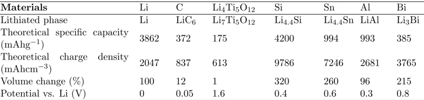
Table 1.2: Comparison of the theoretical specific capacity, charge density, volume change and onset potential of various anode materials.
Materials Li C Li4Ti5O12 Si Sn Al Bi
Lithiated phase Li LiC6 Li7Ti5O12 Li4.4Si Li4.4Sn LiAl Li3Bi
Theoretical specific capacity
(mAhg−1) 3862 372 175 4200 994 993 385
Theoretical charge density
(mAhcm−3) 2047 837 613 9786 7246 2681 3765
Volume change (%) 100 12 1 320 260 96 215
Potential vs. Li (V) 0 0.05 1.6 0.4 0.6 0.3 0.8
The main problem with these alloying materials, is the important volume change during the lithiation/ delithiation processes. The significant volume changes lead to severe cracking and pulverization of the electrode and sub-sequent loss of electrical contact between the individual particles, which in turn results in a severe capacity fading. In order to overcome those problems, considerable research efforts have been devoted to preserve their structural integrity. One of the earliest approaches involves replacing the bulk mate-rial with nanostructured alloys. The unique nanostructure can alleviate the generated mechanical strain due to the volume change as the Li+ion
interca-lated to and de-intercainterca-lated from the host electrode materials. Moreover, it reduces the electronic and ionic transport pathways and provides additional lithium storage sites.[48] The second approach is to form nanocomposites; for example, metal nanoparticles coated with carbon or dispersed in a carbon matrix. Carbonaceous materials have the benefits to accommodate the stress associated with the volume expansion, and have good ionic conductivity.[49] Owing to its highest capacity, silicon has been the main focus in Li-alloying metals. The electrochemical properties of this element as anode in Li-ion batteries are reviewed in Chapter 4.
3. Conversion Materials
Another extensively investigated category of anode materials for LIBs are transi-tion metal oxides (MxOy, where M= can be: Fe, Co, Ni, Cu, Mn, Mo, Ru, etc.).
These metal oxides do not possess vacant sites to accommodate lithium, excluding the possibility of an intercalation mechanism. The actual mechanism involves the formation and decomposition of Li2O, along with the reduction and oxidation of
metal nanoparticles. The conversion reaction can be represented as the following: MO + 2 Li+ + 2 e− Li2O + M
In 2000, Poizot et al. reported for the first time that lithium can be stored re-versibly in transition metal oxides through a conversion reaction.[50] These metal oxides can deliver a stable gravimetric capacity three times higher than that of carbon, and show a high energy density because the oxidation state is completely used and more than one electron is involved in the conversion reaction. However, transition metal oxide anodes still face several issues that keep those materials far from commercial application. The disadvantages include low Coulombic efficiency at the first cycle, large voltage hysteresis between the discharge and charge process, unstable formation of the SEI layer and poor cycling stability.[51] These limitations of transition metal oxides could be possibly overcome by preparing nanostructured transition metal oxides and transition metal oxide nanocomposites to improve the electrochemical performance of transition metal oxide anodes.[52]
1.2.3.3 Electrolyte
Usually in a commercial Li-ion cell, the electrolyte consists of a lithium salt dissolved in a solvent mixture that also contains small amounts of additives. The role of an electrolyte is to transport Li+ ion between the anode and the cathode and to block the transport of electrons. It is at the electrode/ electrolyte interfaces that the redox reactions governing the proper operation of the battery take place. The electrolyte must satisfy the following requirements [53]:
1. High ionic conductivity σLi > 10−4 S cm−1 and low electronic conductivity σe <
10−10 S cm−1,
2. Transference number σLi+/ σtotal ≈1, where σtotalis the sum of the conductivities
of all the other ions in the electrolyte (σLi++σtotal),
3. Chemical stability over ambient temperature,
5. Chemical stability with respect to the electrodes, including the ability to form a passivating SEI layer rapidly, where the kinetic stability is required because the electrode potential lies outside the electrolyte window,
6. High safety, low toxicity and low cost.
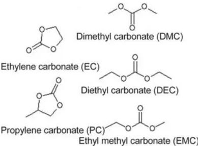
Nevertheless, obtaining all these requirements has been a challenging task up to date. Carbonates are the most popular solvents used for commercial LIBs. They have an oxi-dation potential, the ”highest occupied molecular orbital (HOMO)” at 4.7V vs. Li/Li+ and a reduction potential, the ”lowest unoccupied molecular orbital (LUMO)” near 1.0 V vs. Li/Li+.[53] The most commonly used electrolyte solvents are alkyl carbonates or alkyl carbonate mixtures such as: ethylene carbonate (EC), dimethyl carbonate (DMC), propylene carbonate (PC), diethyl carbonate (DEC) and ethyl methyl carbonate (EMC). The structural formulae of alkyl carbonates are shown in figure1.5.[54]
Figure 1.5: Chemical formulae of the main carbonate solvents used in the electrolyte in Li-ion batteries.
These alkyl carbonates, mixed with lithium salt hexafluorophosphate (LiPF6), are
re-garded as the basic standard electrolyte solutions for LIBs.
Recently, room-temperature ionic liquids (ILs) have been proposed as promising alter-native solvents in electrolytes for the next generation of Li-ion batteries, mainly because of their high oxidation potential (∼ 5.3V vs Li/Li+), their low vapor pressure i.e non
volatile, non-flammable nature, and good chemical electrochemical stability.[55] How-ever, the main drawback in ILs is their high viscosity, which engender reduced conduc-tivities and they are expensive.
Regarding the lithium salt, it provides the lithium source in the electrolyte for the inser-tion/ extraction between the electrodes, while the solvents provide a medium for Li+ion diffusion. Several lithium salts have been studied, such as lithium perchlorate (LiClO4),
lithium tetrafluoroborate (LiBF4), lithium hexafluoroarsenate(V) (LiAsF6), lithium
bis-trifluoromethanesulfonimide (LiTFSI) and lithium bis(oxalato) borate (LiBOB). LiPF6
still remains dominant as it best combines necessary properties/ characteristics: ionic conductivity, dissociation constant, ionic mobility and anodic stability. Nevertheless, it is expensive and forms hydrofluoric acid (HF) in contact with water. The electrolytes must therefore be prepared from perfectly anhydrous solvents and under controlled at-mosphere.
Additionally to lithium salt and solvents, the liquid electrolyte also contains additives that are used for instance to improve formation of the SEI, stabilize LiPF6 and protect
from overcharging. The most commonly used electrolyte additives appear to be viny-lene carbonate (VC) and fluoroethyviny-lene carbonate (FEC). VC is an electrolyte additive, which is commercialized for LIBs in order to increase the Coulombic efficiency and ther-mal stability of graphite.[56] Its influence on the silicon electrodes have also proved to be very encouraging, on thin films of amorphous silicon[57] and on nanostructured sil-icon/ carbon (Si@C).[58] Jaumann et al [58] reported that VC-additive increases the Coulombic efficiency to reach 99% after the 20th cycle and also improved the lifetime of nano-silicon anodes. The use of the FEC additive has been reported in several studies of silicon electrodes for example, on thin films [59] and on silicon nanoparticles.[60] Choi et al [59] were the first to use FEC-added electrolytes with silicon thin film electrodes. They observed that the presence of FEC in the electrolyte resulted in a smoother SEI layer on the silicon film. Lin and coworkers [60] investigated the presence of FEC-based electrolytes for silicon nanoparticle anodes made by a conventional slurry. They reported an outperformance of the electrode in the FEC-based electrolyte in terms of capacity retention and Coulombic efficiency. The enhancement of the performance is due to the better properties of the FEC-derived SEI formed on the surface of the silicon.
In the present work, different electrolytes have been used because for the positive elec-trode (sulfur), it is well know that the carbonate-based solvents such as ethylene car-bonate and diethyl carcar-bonate react with polysulfides irreversibly.[61] An electrolyte solu-tion containing 1 M LiTFSI in a 1:1 (volume ratio) 1,3-dioxolane: 1,2-dimethoxyethane (DOL:DME) with the addition of LiNO3 was used in the electrochemical testing of
the sulfur electrode. Whereas, another electrolyte solution containing 1 M LiPF6 in a
experiments with the addition of FEC was used in the electrochemical testing of the silicon material. In the full cell, the 1 M LiTFSI in a 1:1 (volume ratio) 1,3-dioxolane: 1,2-dimethoxyethane (DOL:DME) with LiNO3 was used.
Solid Electrolyte Interphase
The electrode/ electrolyte interphase is one of the most crucial parameters affecting the LIBs electrochemical performance (i.e. cycling performance, rate capability, safety).[62] In the early 1970s, Peled firstly suggested that the layer formed instantly by the contact of the metal with the solution, acts as an interphase between the metal and the solution and named it the SEI.[63] Negative electrodes such as graphite or silicon operate at potential between 0-1V vs Li/Li+, whereas positive electrodes (e.g. LiCoO2, LiMn2O4)
have an operating potential higher than 3V vs Li/Li+. No electrolyte components can remain thermodynamically stable against reduction potential at negative electrodes and against oxidation potential at the positive electrodes.[64] In the case of carbonaceous electrodes, the formation of the SEI layer proceeds from the deposition of organic and in-organic compounds during the first charge/ discharge cycle on the surface of the graphite electrode. The formed SEI prevents further reduction and co-intercalation of the elec-trolyte and allows only Li+ ion diffusion. Therefore, SEI acts as a protective surface film making the carbon electrode stable even at potentials lower than 1V.
The existence of the SEI on the cathode is still highly debated. In the case of LFP or transition metal oxides, they store Li+ion between 3.5-4.2V, which is still on the border of oxidation stability limits for most electrolyte components. But, when the cathode potential is above 4.2V (e.g., LiNi0,5Mn1,5O4, LiCoPO4,...), the existence of a surface
film on the cathode will become certain.[64,65]
1.2.3.4 Current collectors
Aluminium (Al) and copper (Cu) are usually used as the current collectors at the cathode and the anode, respectively. The collector materials require good electrical conductivity and inertness to any electrochemical lithium reaction at the respective electrodes. Alu-minium is extensively used as a current collector with lithiated transition metal oxides for the positive electrode in commercial LIBs, as it is stable up to 4.3 V vs. Li/Li+
in most organic electrolytes.[66] Its low price and good electric conductivity due to the high purity of Al metal expand the application potential for LIBs.[67] Aluminium was shown in 1971 to alloy with lithium at low potentials vs. Li/Li+.[68] As a result, the use of Al as negative electrode in Li-ion batteries has been hindered because the formation of alloys always results in volume expansion.[67] Copper is used as a current collector for the negative electrodes in almost all commercial LIBs. It has a high conductivity
and is readily available in many forms. At high potential (1.5V to 3.0V vs. Li/Li+), a large cathodic peak was observed in the cyclic voltammogram curve, which corresponds to the corrosion of Cu.[67] At low potential between 0V to 1.0V, there is no peak cor-responding to the Li-Cu alloy in this system since no apparent redox peaks appeared near 0V vs. Li/Li+. This makes Cu a good choice to be used as the negative electrode
current collector in LIBs.[67]
Nevertheless, break up of the metallic foil and detachment of the active materials from the current collectors can be problematic for the future generations of LIBs. A current collector should therefore be lightweight, thin, mechanically stable, durable under de-formation stress and chemically stable.[69] Carbon nanotubes are potential candidates as current collectors owing to their properties [70–73] which will be detailed in Chapter 2.
1.3
Advantages of nanomaterials structure
Micro-sized electrode materials are commonly used in commercial Li-ion batteries. The electrode materials ought to have some specifications, such as high reversible capacity, fast Li+ ion diffusion, ecological, long cycle life, low cost and improved safety hazards. In solid-state, the diffusion coefficient of Li+ ions in most electrode materials is very low (10−7 - 10−11 cm2/s) [74] and, thus, the diffusion path length becomes important and can easily become a limiting factor of the insertion/ extraction rate, and hence of the charge-discharge rate performance. In order, to meet the future demands of EVs and HEVs, the development of new strategies is required for LIBs. One of these strategies is the miniaturization of the electrode materials. The use of nanostructured materials instead of existing micro-sized materials are considered to be the most encouraging strategy to overcome present limitations. Nanostructures can provide reduced distance for Li+ion diffusion path length and can improve the intercalation/ deintercalation rate
of LIBs.[75]
The benefits as well as drawbacks of nanostructured electrode materials are summarized as follows:
Benefits [76]
• Increase charge/ discharge rates due to short distance for Li+ ion diffusion within
the particles,[75]
• Nanostructured materials with high specific surface area permit a high contact area between electrode and electrolyte, enabling high lithium exchange flux,[78] • The nanometer-sized electrode materials can accommodate large volume
expan-sion/ contraction during cycling, preserving the integrity of the electrode and lead-ing to stable cycllead-ing performance,[79]
• Enable reactions that cannot occur in micron-sized particles,[77,80]
• Chemical potential for lithium ions may be modified leading to potential shifts.[75,
81]
Drawbacks [78]
• Difficult to synthesize and control the size or shape of the desired nanometer-sized electrode materials,
• High surface area and high surface energy of nanomaterials also increase undesir-able side reactions between electrode and electrolyte, which may result in a high irreversibility and reduced cycle life,
• The packing density of nanomaterial-based electrodes is lower than that of micromaterial-based electrodes thus reducing the volumetric energy density,
• Electron and Li+ ion transportation through the nanoparticulate layers can be
restricted due to random walk limiting the battery performance and reducing the electrical conductivity. Nanomaterials tend to form agglomerates during the elec-trode fabrication process, making it difficult to uniformly disperse them in the electrodes, and their nanoscale dimensions are rather difficult to control.
1.4
Ideal material
A wide variety of nanostructured materials with miscellaneous geometric shapes and morphologies have been extensively explored, such as nanoparticles (0-D), nanowires (NW), nanorods (NR) and nanotubes (NT) (1-D) and nano films (2-D). Despite the benefits of nanostructured materials, particularly in case of 0-D nanoparticles, their performance is still limited by many factors. Over several cycles, the intercalation/ deintercalation of Li+ ions induce a volume expansion and craking of the nanoparticles, leading to a reduction in the cyclability and the battery life.[82] In addition, nanopar-ticles tend to form agglomerates during the electrode fabrication process resulting in a random paths of electrons and Li+ ions through the nanoparticles. Moreover, the grain
boundaries and voids in between the nanoparticles restrict the battery performance and reduce the overall electrical conductivity.[75,82]
1-D nanostructures are particularly attractive and are considered to be superior to nanoparticles. The small diameter of 1-D nanostructure allows for better accommo-dation of the large volume changes without initiation of mechanical degraaccommo-dation, such as pulverization and fracturing that can occur in bulk or micron-sized materials.[83] To get more advantages from 1-D nanostructures and to avoid poor electronic/ ionic transportation by random paths, each 1-D nanostructure should be directly electrically connected and thus preferably vertically aligned to the metallic macroscopic current col-lector. Thus, a direct 1-D electronic pathway can be achieved which drastically improves the charge transport during the charge and the discharge processes and prevents the re-quirement of conductive additives or binders which add extra weight to the battery.[84] However, the choice of the nanomaterial properties is crucial to avoid any resistance, which may cause the failing of performance (e.g., capacity fading) of the LIBs.
What would then be the ideal 1-D nanostructured material that should be used? The optimal 1-D nanostructured material should be very thin and light-weighted, should ensure optimal Li+ ions conductivity/ electrons transportation, preferably be vertically-aligned and should have a direct electrical contact of each nano-object with the current collector.
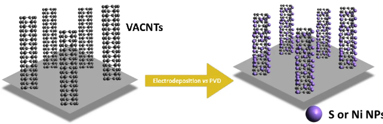
One of the best choices appears to be the carbon nanotubes (CNTs) which will be re-viewed in detail in the next Chapter. Vertically aligned CNTs forest directly grown on an appropriate current collector can provide a quasi-ideal highly conductive phys-ical framework for subsequent formation of 1-D hierarchphys-ical nanostructures of various natures, and enable, for example, the use of nanostructured high-capacity electrode materials as Sulfur and/ or Silicon.
Carbon nanotubes acting as
nanostructured current collectors
The present chapter is divided into two main parts: the first part gives a short and general overview of the main characteristics and properties of the carbon nanotubes. The second part describes the experimental approach used to obtain vertically aligned carbon nanotube (VACNT) carpets on two different conductive substrates: aluminum and copper. In particular, we present the main steps that were developed and optimized for growing reproducible and controlled properties of VACNT carpets using a modified Chemical Vapor Deposition (CVD) process. The benefit of growing VACNTs directly on a conductive substrate, such as copper and/or aluminum is to obtain a direct elec-trical contact of each of the nanotubes with the substrate which makes them very good candidates as current collectors in LIBs. This approach avoids the use of binders or additives, optimizes the active material/ current collector interface and simplifies the fabrication of the battery device.
2.1
Carbon allotropes
In its organic form, carbon has an extremely rich and varied chemistry, whilst in its inorganic form it has various allotropes, including graphite, diamond, fullerene (e.g., buckyball C60), amorphous carbon (a-C), carbon nanotube (CNT) and so on.[85] The
structure of the different carbon allotropes is shown in figure 2.1.
Diamond and graphite are pure forms of carbon, but their physical properties are widely different. Diamond is transparent and the hardest carbon structure.[86] It has a tetra-hedral structure, i.e, each carbon atom is surrounded by four other carbon atoms with
a b
e
c
d
Figure 2.1: Structure of different allotropes of carbon: (a) Diamond, (b) Graphite, (c) C60( Buckminsterfullerene or buckyball), (d) Amorphous
car-bon, (e) Single-wall carbon nanotube or buckytube.
tetrahedral connections. The conductivity of diamond is extremely low due to the lack of free electrons, since all the valence electrons are used to form the sp3 bonds.[87] In contrast, graphite is black, very soft and slippery. Its structure consists of Van der Waals stacked graphene layers (a single, tightly packed layer of carbon atoms bonded together in a hexagonal honeycomb lattice). It has high thermal and electrical conductivity. The properties of graphite from its crystalline structure, for example its high electrical con-ductivity is related to the π bonding between the carbon atoms in the graphene layers. The softness and lubricating nature of graphite arises from the weak Van der Waals forces binding the carbon sheets. The amorphous carbon (disordered carbon) having no crystalline structure, results in a totally random distribution of sp2 and sp3 hybridized carbon atoms.
A new era in carbon materials began in the middle of the 1980s when the discovery of carbon nanostrutures triggered an ever-growing research interest. These carbon nanos-tructures include: fullerenes - the most common one is the buckyball-like molecules (i.e. fullerene C60) and the CNTs. Fullerenes were discovered in 1985 by Kroto et al
during the vaporization of graphite by laser irradiation, producing a remarkably stable cluster consisting of 60 carbon atoms arranged in hexagons and pentagons.[88] Carbon nanotubes were theoretically imagined and described as ”rolled up” sheets of graphene. The first observation of the tubular structure of some nano-sized carbon filament was in 1952 by Radushkevich and Lukyanovich.[89] Experimental evidence of the existence of
CNT dates back to 1991 when Iijima observed multiwalled carbon nanotubes (MWC-NTs) using a transmission electron microscopy.[90] In 1993, Iijima et al [91] and Bethune et al [92] simultaneously and independently reported the existence of CNT consisting of a cylindrical graphene sheet called single walled carbon nanotubes (SWCNTs). Carbon nanotubes stimulated an ever increasing interest from the whole scientific community; physicists, chemists, and materials scientists due to their varied and astonishing prop-erties (electronic, physical, mechanical) that can find potential use in wide range of applications.
2.2
Carbon nanotubes
Carbon nanotubes have a cylindrical structure where each C shares a sp2 covalent bond with its three nearest-neighboring atoms. CNTs can be viewed as a graphene sheet rolled up into a nanotube. CNTs have a typical diameter of 1-5 nm, about 100,000 times thinner than an average human hair, and they can be several hundred microns long. CNTs may be broadly classified into SWCNTs and MWCNTs based on their structure as shown in figure 2.2. A MWCNT constitutes of several cylindrical sheets, generally between 2 and 50, each corresponding to a graphitic plane. Different possible structures of MWCNTs are described in literature. A CNT containing another tube inside it is referred to the Russian Doll model, while a single graphene sheet wrapped around itself manifold times is called the Parchment model.[93] The internal diameter of the tube ranges between 1 and 40 nm and its external diameter ranges between 2 to 100 nm. Its length is of the order of microns, but can reach few centimeters. The distance between the successive walls, determined for the first time by Iijima, is 0.34 nm, slightly greater with respect to the graphite interplane distance (0.33 nm). This difference is not only due to the constraints caused by the tube curvature, but also to the strengths of Van der Waals forces between the sheets comprising the nanotube. A SWCNT consists of a single graphene sheet rolled up and closed on itself. The way this sheet is rolled determines the tubes helicity. Regarding its size characteristics, a SWCNT presents a perfectly rectilinear tubular structure of nanometer diameter, between 1 and 50 nm, and of micrometric length. Its exceptional physicochemical properties result from its structural characteristics (cylindrical shape, helicity, nanometric size and aspect ratio or length to diameter).