1546 Page 1
Working fluid selection and operating maps for Organic Rankine Cycle expansion
machines
Sylvain QUOILIN1*, Sébastien DECLAYE, Arnaud LEGROS, Ludovic GUILLAUME, Vincent LEMORT
1
University of Liège, Thermodynamics Laboratory, Liège, Belgium Phone: +32 4 366 4822 Fax: +32 4 366 4812 e-mail: [email protected]
* Corresponding Author
ABSTRACT
Fluid selection for the Organic Rankine Cycle has been the object of an abundant literature. Most of the scientific publications focus on the cycle thermodynamic efficiency in order to select the best candidate. However, other thermodynamics properties, such as molar mass, or vapor density condition the whole design of the cycle, and its cost. For example, the molar mass influences the number of stages required in the case of an axial turbine; the volume ratio between expander supply and exhaust conditions the possibility to use a volumetric expander (whose internal volume ratio is limited); the vapor density at the expander exhaust determine the size of the expander, and of the condenser; etc.
This paper considers a whole range of ORC applications, in terms of power (from the kW-scale to the multi-MW plants), heat source temperature (from 90°C to more than 300°C) or heat source nature (solar, biomass, waste heat recovery, geothermy, etc.). For each of these applications, a screening of the available fluids is performed, and their thermodynamics performance are compared with respect to the foreseen application.
A detailed analysis of the most common expansion machines is then conducted, by comparing their respective operating maps for each fluid and for each application type. The considered expansion machines are the radial-inflow turbine, the screw expander, and the scroll expander, since they are the most widely used in commercial applications and/or in scientific literature.
1. INTRODUCTION
Selection of Organic Rankine Cycle working fluids has been treated in a large amount of scientific publications. Most of the time, these works propose a comparison between a set of candidate working fluids in terms of thermodynamic performance and based on a thermodynamic model of the cycle.
Since the optimal working conditions are closely linked to the selected working fluid, an optimization must be performed for each screened medium. When selecting the most appropriate working fluid, the following guidelines and indicators should be taken into account:
• Thermodynamic performance: the efficiency and/or output power should be as high as possible for given
heat source and heat sink temperatures. This performance depends on a number of interdependent thermodynamic properties of the working fluid: critical point, acentric factor, specific heat, density, etc. It is uneasy to define an optimum for each specific thermodynamic property independently. The solution consists in simulating the cycle with a thermodynamic model and compare the fluids in terms of cycle efficiency and/or output power.
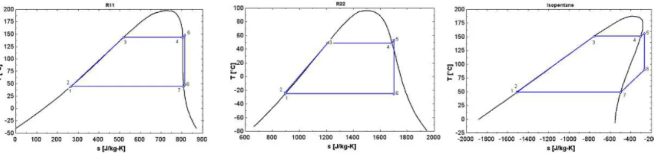
• Positive or isentropic saturation vapor curve. As previously detailed in the case of water, a negative
saturation vapor curve (“Wet” fluid) leads to droplets at the end of the expansion. The vapor must therefore be superheated at the turbine inlet to avoid turbine damages. In the case of positive saturation vapor curve
1546 Page 2
(“Dry” fluid), a recuperator can be used in order to increase cycle efficiency. This is illustrated in Figure 1 with isopentane, R11 and R12.• High vapor density: this parameter is of key importance, especially for fluids showing a very low
condensing pressure (e.g. silicon oils). A low density leads to a higher volume flow rate: the pressure drops in the heat exchangers are increased, and the size of the expander must be increased. This has a non-negligible impact on the cost of the system. It should however be noted that larger volume flow rates might allow the design of turboexpanders, for which the size is not a crucial parameter.
• Low viscosity: a low viscosity both in the liquid and vapor phases is required to maintain high heat transfer
coefficients and low friction losses in the heat exchangers.
• High conductivity is required to obtain a high heat transfer coefficient in the heat exchangers.
• Acceptable evaporating pressure: as already stated with water, high pressures usually lead to higher
investment costs and increased complexity.
• Positive condensing gauge pressure: the low pressure should be higher than the atmospheric pressure in
order to avoid air infiltration in the cycle.
• High stability temperature: unlike water, organic fluids usually suffer chemical deteriorations and
decomposition at high temperatures. The maximum heat source temperature is therefore limited by the chemical stability of the working fluid.
• The melting point should be lower than the lowest ambient temperature through the year to avoid the
freezing of the working fluid.
• High safety level: Safety includes two main parameters: the toxicity and the flammability. The ASHRAE
Standard 34 classifies refrigerants in safety groups and can be used for the evaluation of a fluid.
• Low Ozone Depleting Potential (ODP): The ozone depleting potential is measured with comparison to the
ODP of the R11, set to the unity. The ODP of current refrigerants is either null either very close to zero, since non-null ODP fluids are progressively being phased out by the Montreal Protocol.
• Low Greenhouse Warming Potential (GWP): GWP is measured with comparison to the GWP of CO2, set to the unity. Although some refrigerants can reach a GWP value as high as 1000, there is no legislation restricting the use of high GWP fluids.
• Good availability and low cost: Fluids already used in refrigeration or in the chemical industry are easier to
obtain and more cost-effective.
Figure 1: Examples of isentropic, wet and dry fluids
While fluid selection studies in the scientific literature cover a broad range of working fluids, only a few fluids are actually used in commercial ORC power plants. These fluids are the following, classified in terms of critical temperature (Quoilin & Lemort, 2009):
HFC-134a: Used in geothermal power plants or in very low temperature waste heat recovery. HFC-245fa: Low temperature working fluid, mainly used in waste heat recovery
n-pentane: Used in the only commercial solar ORC power plant in Nevada. Other applications include waste heat recovery and medium temperature geothermy.
Solkatherm: Waste heat recovery
OMTS: CHP power plants
1546 Page 3
In general, the selected fluid shows a critical temperature slightly higher than the target evaporation temperature: if the evaporation is taken too far away from the critical temperature – for example if toluene (Tc = 319°C) is evaporated at 100°C – the vapor density is very low in both the high and low pressure sides, which causes high pressure drops and the need for bigger components.2. TRADITIONAL APPROACHES TO WORKING FLUID SELECTION
The most common method for working fluid selection is here referred as the "screening" method:: it consists in building a steady-state simulation model of the ORC cycle and run it with different working fluids. The proposed model can be more or less detailed, and the selected cycle performance indicators can vary from one publication to another.
A review of the the scientific literature in the field of working fluid selection was proposed by the authors in (Quoilin et al., 2011): it compares the different papers in terms of three characteristics: the target application, the considered condensing temperature and the considered evaporating temperature range.
It was shown that, despite the multiplicity of the working fluid studies, no single fluid has been identified as optimal for the ORC. This is due to the different hypotheses required to perform the fluid comparison:
• Some authors consider the environmental impact (ODP, GWP), the flammability, the toxicity of the working fluid, while some others don’t.
• Different working conditions (e.g. the considered temperature ranges) have been assumed, leading to different optimal working fluids.
• The objective functions of the optimization might vary depending on the target application: in CHP or solar application the cycle efficiency is usually maximized, while in WHR applications, the output power should be maximized.
It follows that, since no working fluid can be flagged as optimal, the study of the working fluid candidates should be integrated into the design process of any ORC system.
In many studies (Aljundi, 2011, Badr et al., 1990, Desai & Bandyopadhyay, 2009, Drescher & Brüggemann, 2007, Façao et al., 2008, Gu et al., 2009, Hung, 2001, Mago et al., 2008, Maizza & Maizza, 2001, Roy et al., 2011, Vaja & Gambarotta, 2010, Wang et al., 2011), it appears that the recommended fluid is the one with the highest critical temperature, i.e. the plant efficiency could be further improved by selecting even higher critical point working fluids (Liu et al., 2004). However, a high critical temperature also involves working at specific vapor densities much lower than the critical density. This reduced density shows a high impact on the design of the cycle, since the components need to be oversized for two practical reasons:
• Low densities involve high fluids velocities and therefore higher pressure drops. The fluid velocity must therefore be reduced by increasing the hydraulic diameter of the pipes and heat exchangers.
• The size of the expansion machine must be increased to absorb a higher volume flow rate.
This leads to the conclusion that additional criteria must be added to the sole thermodynamic efficiency when comparing working fluids.
Very few studies include additional parameters taking into account the practical design of the ORC system, mainly because of the difficulty to define a proper function for the multi-objective optimization of the cycle. Examples of such studies are provided in (Lakew & Bolland, 2010, Papadopoulos et al., 2010, Quoilin et al., 2011, Wang et al., 2012), where a fluid selection taking into account the required heat exchange area, turbine size, cost of the system, dangerousness, etc. is provided. These studies show that taking the economics into account can lead to the selection of very different optimal operating conditions and working fluids. Those methods should therefore be preferred to the simplistic thermodynamic benchmarking of candidate working fluids.
3. WORKING FLUID SELECTION: THE OPERATING MAP APPROACH
In most cases, the selection of the working fluid is linked to that of the expansion machine: selecting a certain type of expander makes the use of a series of working fluids possible while others must be rejected. In the same manner, when a working fluid is selected, not all types of expansion machines are suitable for the imposed working conditions.
1546 Page 4
This method aims at providing a preselection tool for selecting the most suitable combinations of working fluid / expansion machine for a wide range of working conditions typical of ORC systems.This is achieved by building an operating map of each combination in terms of condensing and evaporating temperatures, taking into account the practical limitations of each expansion machine. The power ranges suitable to each combination are then evaluated.
Limitations of volumetric expanders
Volumetric expanders are characterized by a built-in volume ratio, which corresponds to the volumetric increase of the pocket in which the fluid is trapped after the suction process (Lemort et al., 2008). As shown in (Lemort et al., 2009), over and under-expansion losses can easily be computed by summing an isentropic expansion and a constant-volume expansion:
Isentropic expansion:
– in (1)
in being the isentropic enthalpy at pressure in.
Constant volume expansion:
in in– (2)
is positive in case of under-expansion, and negative in case of over-expansion. The total expansion work is then obtained by summing w1 and w2.
The internal expansion isentropic efficiency is therefore given by:
in (3)
The maximum internal built-in volume ratio of positive-displacement expander is usually not higher than 5. It is limited by the length of the rotor (bending stresses) in the case of a screw expander and by the number of spiral revolutions in the case of a scroll expander. This is an important limitation since most ORCs operate at much higher volume ratios.
However, allowing a small under-expansion can substantially increase the volume ratio over the expander with a limited penalty on the efficiency. It is therefore economically viable for volumetric expanders to operate at a slightly lower internal built-in volume ratio than the ideal one.
For this analysis an under-expansion leading to an internal expansion isentropic efficiency of 0.9 is considered as acceptable.
The second main limitation of volumetric expanders is the swept volume. This swept volume is linked to the maximum rotor diameter in the case of screw expanders (about 400mm) or to the maximum spiral height and diameter in the case of a scroll expander.
To determine the boundary working conditions of volumetric expander, it seems reasonable to take profit of the experience acquired for volumetric compressors in the refrigeration field and assume that the absorbed volumetric flow rates of the machine should be similar.
After a screening of the available scroll and screw compressors on the market, the boundaries provided in Table 1 are adopted.
Table 1: Boundary working conditions for the volumetric expanders
˙ , ˙ , ,in, in
Scroll 1.1 l/s 49 l/s 4 > 0.9
Screw 25 l/s 1100 l/s 5 > 0.9
The boundary volume flow rates are given in compressor mode, which corresponds to the exhaust volumetric flow rates of the expander.
Since positive displacement machines can absorb a limited flow rate, it is not advisable to run them with low vapor density fluids: the mass flow rate through the expander being low, the output power is reduced. The limitation on the vapor density results of an economical trade-off that is out of the scope of this work. However, the experience gained in the compressor market can be used and transposed to the expander technology.
A new performance indicator, the volume coefficient, is defined as the ratio between the expander volume flow rate and the output power:
1546 Page 5
˙ , ! "˙
, !
#$³ &'⁄ ) (4)
A screening of the refrigeration and heat pump applications shows that for a compressor, this ratio (defined with the exhaust volume flow rate) is roughly comprised between 0.25 and 0.6 m³/MJ. For the present work, a maximum value of 0.5 is selected.
3.1 Limitations of the turbine technology
The following developments are applied to the particular case of a 90° IFR radial-inflow turbine, but a similar analysis could easily be transposed to alternatives turbine designs, such as single-stage axial turbines.
It is uneasy to define a firm limit for each turbine parameter since these parameters are sometimes set empirically by the turbine manufacturers, stating that exceeding a certain values reduces the efficiency. Moreover, these boundary values sometimes vary from one manufacturer to another. For the purpose of this work, the selected boundary values are extracted from the scientific literature and from discussions with turbine manufacturers. They should not, however, be considered as absolute constraints. In particular, the current experience and textbooks regarding turbine design do not cover the case of high-expansion ratios with organic working fluids. The ongoing scientific works aiming at addressing this gap (see for example (Harinck et al., 2010) might displace the current boundaries.
A first important limitation of turbines is the maximal allowable tip speed U2, given by:
* + , - (5)
D2 being the wheel diameter and N the rotating speed.
As a general rule, a high tip speed is always preferred since it increases the stage specific work. It is however limited by the strength of materials at the wheel periphery. A maximum value of 370 m/s is chosen.
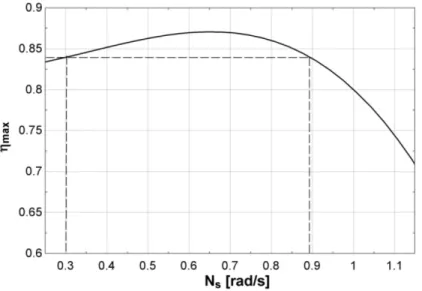
The maximum turbine efficiency is generally well described by its specific speed Ns, given by:
,. 2 + ,
0 ˙
1.34# 56) (6)
Where ˙ is the exhaust volume flow rate and is the isentropic enthalpy drop. Figure 2 shows a typical wheel efficiency curve based on manufacturer data: the given efficiency is the maximum efficiency for a given specific speed, i.e. the efficiency obtained when the ratio U2/Cs is optimized for the given working conditions, where Cs is the isentropic speed, given by:
0 2 (7)
For the present analysis a minimum wheel efficiency of 84% is assumed, which corresponds to a specific speed varying roughly between 0.3 and 0.9 (Figure 2).
1546 Page 6
This value is in good agreement with Dixon's recommended optimal boundaries for radial turbines, comprised between 0.3 and 1 (Dixon, 2005).An important limitation of single stage radial inflow turbines is the maximum Mach numbers in both the turbine nozzle and rotor.
The turbine speed triangles are calculated with the following assumptions: The degree of reaction is set to 50%
The ratio between inner and outer wheel diameters is set to 0.3
Choked flow should be avoided in the whole rotor, the critical part being the rotor exhaust (point 3). The Mach number is calculated by:
&7 "7
8 9,7 (8)
W3 being the relative speed at the rotor exhaust and Csound,3 the sound speed at the same place. A maximum Mach number of 0.85 is generally recommended in order to avoid any local choking of the flow in the rotor.
The maximum Mach number in the turbine nozzle constraints the maximum allowable pressure/volume ratio over the turbine. Most turbine manufacturers allow the nozzle flow to be supersonic, but a too high Mach number might decrease the efficiency and should be avoided. For the present analysis, a maximum value of 1.8 is selected.
&
8 9, (9)
The order of magnitude of the tip speed U2 is usually quite independent from the size of the turbine (Persson, 1990). Micro-scale turbines therefore show a very high rotational speed since D2 is low in Eq 5. Decreasing the nominal turbine power therefore increases the bearing losses, which can become prohibitive compared to the output power. A maximum rotational speed can therefore be defined: (De Vlaminck, 1988) recommends a maximum speed of 50,000 rpm, while (Sauret & Rowlands, 2011) selected a number of 24,000 rpm. For the present work a value of 50,000 rpm is selected.
Turbines can usually absorb a much higher flow rate than volumetric expanders for a given machine size (i.e. wheel diameter). A limitation on the volume factor, as set for the scroll and screw technologies, is therefore not taken into account for this technology.
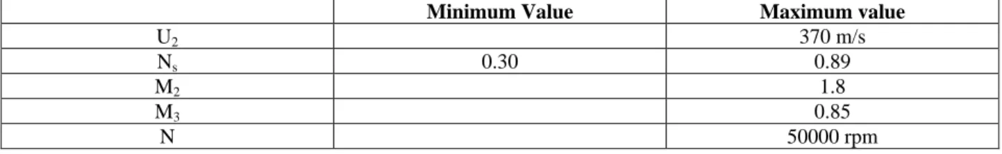
A summary of the turbine boundaries is provided in Table 2.
Table 2: Boundary conditions for the radial inflow turbine
Minimum Value Maximum value
U2 370 m/s Ns 0.30 0.89 M2 1.8 M3 0.85 N 50000 rpm 3.1 Operating maps
The limitations described in the previous sections can be used to build a map of the allowable working conditions in a Tev/Tcd diagram. Figure 3 and Figure 4 show the envelope mapping of the scroll and screw technologies respectively for a few typical ORC working fluids.
Five typical ORC applications have been overlaid on the operating maps in the form of dots. They illustrate how the map can be exploited: if a single-stage scroll expander can be used for a low-temperature geothermal application (90/20°C) or even for a low temperature solar application (120°C/30°C), it is not suitable for applications working with higher evaporating temperatures, such low or higher temperature waste heat recovery, or biomass CHP. It can be noted that the maps of the screw expander are wider than that of the scroll expander. This is due to a higher maximum volume ratio.
The upper left curve of each map is defined by the limitation on the under-expansion losses. The down right curve is defined by the limitation on the volume coefficient, and the upper line is given by the critical temperature of the fluid.
Figure 3: Scroll expander operating map
Figure 3 and Figure 4 also show that both volumetric expander
applications because of a too high volume ratio. The obvious solution in this case would be to assemble several expanders in series. It should be mentioned that no restriction has been defined regardin
temperature at the expander inlet. Refrigeration compressors are usually not operated over a temperature of 150°C. Volumetric expanders using toluene or OMTS might therefore not be feasible due to too high thermal expansion or stresses.
The mapping of the radial inflow turbine is presented in Figure 5. The right curve of each map corresponds to the maximum specific speed of the turbine. The upper line is defined by the critical temperature since this works only focuses on subcriti
OMTS and HFE7000 but corresponds to the minimum specific speed for HFC and n-pentane.
: Scroll expander operating map the down right
Figure 3 and Figure 4 also show that both volumetric expander
applications because of a too high volume ratio. The obvious solution in this case would be to assemble several expanders in series. It should be mentioned that no restriction has been defined regardin
temperature at the expander inlet. Refrigeration compressors are usually not operated over a temperature of 150°C. Volumetric expanders using toluene or OMTS might therefore not be feasible due to too high thermal expansion or The mapping of the radial inflow turbine is presented in Figure 5. The right curve of each map corresponds to the maximum specific speed of the turbine. The upper line is defined by the critical temperature since this works only focuses on subcritical ORCs. The left curve is the limitation on the maximum Mach number at point 2 for Toluene, OMTS and HFE7000 but corresponds to the minimum specific speed for HFC
pentane.
: Scroll expander operating map
the down right-hand corner corresponds to a too high volume flow rate)
Figure 4
Figure 3 and Figure 4 also show that both volumetric expander
applications because of a too high volume ratio. The obvious solution in this case would be to assemble several expanders in series. It should be mentioned that no restriction has been defined regardin
temperature at the expander inlet. Refrigeration compressors are usually not operated over a temperature of 150°C. Volumetric expanders using toluene or OMTS might therefore not be feasible due to too high thermal expansion or The mapping of the radial inflow turbine is presented in Figure 5. The right curve of each map corresponds to the maximum specific speed of the turbine. The upper line is defined by the critical temperature since this works only cal ORCs. The left curve is the limitation on the maximum Mach number at point 2 for Toluene, OMTS and HFE7000 but corresponds to the minimum specific speed for HFC
: Scroll expander operating map (the top left
hand corner corresponds to a too high volume flow rate)
Figure 4: Screw expander operating map Figure 3 and Figure 4 also show that both volumetric expander
applications because of a too high volume ratio. The obvious solution in this case would be to assemble several expanders in series. It should be mentioned that no restriction has been defined regardin
temperature at the expander inlet. Refrigeration compressors are usually not operated over a temperature of 150°C. Volumetric expanders using toluene or OMTS might therefore not be feasible due to too high thermal expansion or The mapping of the radial inflow turbine is presented in Figure 5. The right curve of each map corresponds to the maximum specific speed of the turbine. The upper line is defined by the critical temperature since this works only cal ORCs. The left curve is the limitation on the maximum Mach number at point 2 for Toluene, OMTS and HFE7000 but corresponds to the minimum specific speed for HFC
(the top left-hand corner corresponds to a too high expansion ratio, while hand corner corresponds to a too high volume flow rate)
: Screw expander operating map
Figure 3 and Figure 4 also show that both volumetric expander types are not adapted to the three higher temperature applications because of a too high volume ratio. The obvious solution in this case would be to assemble several expanders in series. It should be mentioned that no restriction has been defined regardin
temperature at the expander inlet. Refrigeration compressors are usually not operated over a temperature of 150°C. Volumetric expanders using toluene or OMTS might therefore not be feasible due to too high thermal expansion or The mapping of the radial inflow turbine is presented in Figure 5. The right curve of each map corresponds to the maximum specific speed of the turbine. The upper line is defined by the critical temperature since this works only cal ORCs. The left curve is the limitation on the maximum Mach number at point 2 for Toluene, OMTS and HFE7000 but corresponds to the minimum specific speed for HFC
hand corner corresponds to a too high expansion ratio, while hand corner corresponds to a too high volume flow rate)
: Screw expander operating map
types are not adapted to the three higher temperature applications because of a too high volume ratio. The obvious solution in this case would be to assemble several expanders in series. It should be mentioned that no restriction has been defined regardin
temperature at the expander inlet. Refrigeration compressors are usually not operated over a temperature of 150°C. Volumetric expanders using toluene or OMTS might therefore not be feasible due to too high thermal expansion or The mapping of the radial inflow turbine is presented in Figure 5. The right curve of each map corresponds to the maximum specific speed of the turbine. The upper line is defined by the critical temperature since this works only cal ORCs. The left curve is the limitation on the maximum Mach number at point 2 for Toluene, OMTS and HFE7000 but corresponds to the minimum specific speed for
HFC-hand corner corresponds to a too high expansion ratio, while hand corner corresponds to a too high volume flow rate)
types are not adapted to the three higher temperature applications because of a too high volume ratio. The obvious solution in this case would be to assemble several expanders in series. It should be mentioned that no restriction has been defined regarding the maximum allowable temperature at the expander inlet. Refrigeration compressors are usually not operated over a temperature of 150°C. Volumetric expanders using toluene or OMTS might therefore not be feasible due to too high thermal expansion or The mapping of the radial inflow turbine is presented in Figure 5. The right curve of each map corresponds to the maximum specific speed of the turbine. The upper line is defined by the critical temperature since this works only cal ORCs. The left curve is the limitation on the maximum Mach number at point 2 for Toluene,
-134a, HFC-245fa, and HCFC
1546 Page
hand corner corresponds to a too high expansion ratio, while
types are not adapted to the three higher temperature applications because of a too high volume ratio. The obvious solution in this case would be to assemble several g the maximum allowable temperature at the expander inlet. Refrigeration compressors are usually not operated over a temperature of 150°C. Volumetric expanders using toluene or OMTS might therefore not be feasible due to too high thermal expansion or The mapping of the radial inflow turbine is presented in Figure 5. The right curve of each map corresponds to the maximum specific speed of the turbine. The upper line is defined by the critical temperature since this works only cal ORCs. The left curve is the limitation on the maximum Mach number at point 2 for Toluene,
245fa, and HCFC
Page 7
hand corner corresponds to a too high expansion ratio, while
types are not adapted to the three higher temperature applications because of a too high volume ratio. The obvious solution in this case would be to assemble several g the maximum allowable temperature at the expander inlet. Refrigeration compressors are usually not operated over a temperature of 150°C. Volumetric expanders using toluene or OMTS might therefore not be feasible due to too high thermal expansion or The mapping of the radial inflow turbine is presented in Figure 5. The right curve of each map corresponds to the maximum specific speed of the turbine. The upper line is defined by the critical temperature since this works only cal ORCs. The left curve is the limitation on the maximum Mach number at point 2 for Toluene, 245fa, and HCFC-123
For all fluids except n tip speed U
usually reached before the maxim
specific speed curve is split into a lower part (below 150°C) corresponding to M corresponding to U
It can be stated that the capabilities of the r
since only one of the typical applications is outside the defined maps. For those special conditions corresponding to very high volume ratios, a multi
Each expansion machine technology is adapted to a specific power range. The maximum and minimum volume flow rates as well as the maximum turbine speed can be used to define a power range for each application. This involves selecting a fl
association is selected: HFC and HCFC
Figure 6 shows the obtained power range for the low temperature application and each expander technology. It is obvious that the scroll technology is the one allowing the lowest output power (a few hundred watts), while the radial inflow is the technology
Figure 6
For all fluids except n-pentane, the maximum Mach number at point 3 was reached before reaching the maximum tip speed U2. This situation usually occurs with high molecular weight fluids, while the maximum tip speed is usually reached before the maxim
specific speed curve is split into a lower part (below 150°C) corresponding to M corresponding to U2=370 m/s.
It can be stated that the capabilities of the r
since only one of the typical applications is outside the defined maps. For those special conditions corresponding to very high volume ratios, a multi
Each expansion machine technology is adapted to a specific power range. The maximum and minimum volume flow rates as well as the maximum turbine speed can be used to define a power range for each application. This involves selecting a fluid for each one of these applications. Taking into account the previous analysis, the following association is selected: HFC
and HCFC-123 for the low temperature WHR cycle.
Figure 6 shows the obtained power range for the low temperature application and each expander technology. It is obvious that the scroll technology is the one allowing the lowest output power (a few hundred watts), while the radial inflow is the technology
Figure 6: Allowed power range for the low temperature applications and each type of expansion machine Figure 5
pentane, the maximum Mach number at point 3 was reached before reaching the maximum . This situation usually occurs with high molecular weight fluids, while the maximum tip speed is usually reached before the maximum Mach number when using air or steam. In the case of pentane, the minimum specific speed curve is split into a lower part (below 150°C) corresponding to M
=370 m/s.
It can be stated that the capabilities of the r
since only one of the typical applications is outside the defined maps. For those special conditions corresponding to very high volume ratios, a multi-stage axial turbine technology sh
Each expansion machine technology is adapted to a specific power range. The maximum and minimum volume flow rates as well as the maximum turbine speed can be used to define a power range for each application. This uid for each one of these applications. Taking into account the previous analysis, the following association is selected: HFC-134a for the geothermal cycle, HFC
123 for the low temperature WHR cycle.
Figure 6 shows the obtained power range for the low temperature application and each expander technology. It is obvious that the scroll technology is the one allowing the lowest output power (a few hundred watts), while the radial inflow is the technology with the highest output power.
: Allowed power range for the low temperature applications and each type of expansion machine Figure 5: Radial inflow turbine operating
pentane, the maximum Mach number at point 3 was reached before reaching the maximum . This situation usually occurs with high molecular weight fluids, while the maximum tip speed is um Mach number when using air or steam. In the case of pentane, the minimum specific speed curve is split into a lower part (below 150°C) corresponding to M
It can be stated that the capabilities of the radial inflow turbine are broader than that of the volumetric expander, since only one of the typical applications is outside the defined maps. For those special conditions corresponding to
stage axial turbine technology sh
Each expansion machine technology is adapted to a specific power range. The maximum and minimum volume flow rates as well as the maximum turbine speed can be used to define a power range for each application. This uid for each one of these applications. Taking into account the previous analysis, the following
134a for the geothermal cycle, HFC 123 for the low temperature WHR cycle.
Figure 6 shows the obtained power range for the low temperature application and each expander technology. It is obvious that the scroll technology is the one allowing the lowest output power (a few hundred watts), while the
with the highest output power.
: Allowed power range for the low temperature applications and each type of expansion machine : Radial inflow turbine operating
pentane, the maximum Mach number at point 3 was reached before reaching the maximum . This situation usually occurs with high molecular weight fluids, while the maximum tip speed is um Mach number when using air or steam. In the case of pentane, the minimum specific speed curve is split into a lower part (below 150°C) corresponding to M
adial inflow turbine are broader than that of the volumetric expander, since only one of the typical applications is outside the defined maps. For those special conditions corresponding to
stage axial turbine technology should be selected.
Each expansion machine technology is adapted to a specific power range. The maximum and minimum volume flow rates as well as the maximum turbine speed can be used to define a power range for each application. This uid for each one of these applications. Taking into account the previous analysis, the following
134a for the geothermal cycle,
HFC-Figure 6 shows the obtained power range for the low temperature application and each expander technology. It is obvious that the scroll technology is the one allowing the lowest output power (a few hundred watts), while the
with the highest output power.
: Allowed power range for the low temperature applications and each type of expansion machine : Radial inflow turbine operating map
pentane, the maximum Mach number at point 3 was reached before reaching the maximum . This situation usually occurs with high molecular weight fluids, while the maximum tip speed is um Mach number when using air or steam. In the case of pentane, the minimum specific speed curve is split into a lower part (below 150°C) corresponding to M
adial inflow turbine are broader than that of the volumetric expander, since only one of the typical applications is outside the defined maps. For those special conditions corresponding to
ould be selected.
Each expansion machine technology is adapted to a specific power range. The maximum and minimum volume flow rates as well as the maximum turbine speed can be used to define a power range for each application. This uid for each one of these applications. Taking into account the previous analysis, the following -245fa for the low temperature solar application Figure 6 shows the obtained power range for the low temperature application and each expander technology. It is obvious that the scroll technology is the one allowing the lowest output power (a few hundred watts), while the
: Allowed power range for the low temperature applications and each type of expansion machine pentane, the maximum Mach number at point 3 was reached before reaching the maximum . This situation usually occurs with high molecular weight fluids, while the maximum tip speed is um Mach number when using air or steam. In the case of pentane, the minimum specific speed curve is split into a lower part (below 150°C) corresponding to M3=0.85 and higher part adial inflow turbine are broader than that of the volumetric expander, since only one of the typical applications is outside the defined maps. For those special conditions corresponding to
ould be selected.
Each expansion machine technology is adapted to a specific power range. The maximum and minimum volume flow rates as well as the maximum turbine speed can be used to define a power range for each application. This uid for each one of these applications. Taking into account the previous analysis, the following 245fa for the low temperature solar application Figure 6 shows the obtained power range for the low temperature application and each expander technology. It is obvious that the scroll technology is the one allowing the lowest output power (a few hundred watts), while the
: Allowed power range for the low temperature applications and each type of expansion machine
1546 Page
pentane, the maximum Mach number at point 3 was reached before reaching the maximum . This situation usually occurs with high molecular weight fluids, while the maximum tip speed is um Mach number when using air or steam. In the case of pentane, the minimum =0.85 and higher part adial inflow turbine are broader than that of the volumetric expander, since only one of the typical applications is outside the defined maps. For those special conditions corresponding to Each expansion machine technology is adapted to a specific power range. The maximum and minimum volume flow rates as well as the maximum turbine speed can be used to define a power range for each application. This uid for each one of these applications. Taking into account the previous analysis, the following 245fa for the low temperature solar application Figure 6 shows the obtained power range for the low temperature application and each expander technology. It is obvious that the scroll technology is the one allowing the lowest output power (a few hundred watts), while the
: Allowed power range for the low temperature applications and each type of expansion machine
Page 8
pentane, the maximum Mach number at point 3 was reached before reaching the maximum . This situation usually occurs with high molecular weight fluids, while the maximum tip speed is um Mach number when using air or steam. In the case of pentane, the minimum =0.85 and higher part adial inflow turbine are broader than that of the volumetric expander, since only one of the typical applications is outside the defined maps. For those special conditions corresponding to Each expansion machine technology is adapted to a specific power range. The maximum and minimum volume flow rates as well as the maximum turbine speed can be used to define a power range for each application. This uid for each one of these applications. Taking into account the previous analysis, the following 245fa for the low temperature solar application Figure 6 shows the obtained power range for the low temperature application and each expander technology. It is obvious that the scroll technology is the one allowing the lowest output power (a few hundred watts), while the
1546 Page 9
3. CONCLUSIONS
Despite the large amount of working fluid studies for ORC applications, their conclusions do not lead to one single optimal fluid for a given temperature level and a given application. This is mainly due to the diversity of the selected objective functions when screening working fluids.
Two approaches for fluid selection have been discussed in this paper: the screening method and the operating map method.
Screening of working fluids is by far the most common approach in the scientific literature. A thermodynamic model is built and the working fluid performances are compared in terms of first-law efficiency, output power or generated irreversibilities. The main issue linked to this approach is the objective function, which does not take into account additional fluid properties influencing the practical design of the cycle. This can lead to recommendation of unrealistic working fluids, such as toluene or benzene for a very low temperature heat source.
The proposed operating map approach focuses on the interaction between expansion machine and working fluid. It provides operating maps of acceptable conditions, i.e. leading to acceptable efficiencies and acceptable component sizes. Compared to the screening method, it shows the advantage of setting limits on the component size and therefore does not lead to unrealistic working fluids. However, the operating maps of different working fluids are often overlapping. This method must therefore be considered as preselection tool only. It must be followed by a more accurate fluid selection procedure.
NOMENCLATURE
C absolute speed [m/s] Subscripts
D diameter [m] 2 nozzle exhaust
h heat transfer coefficient [W/m²K] 3 rotor exhaust
&: mass flow rate [kg/s] ex e xhaust
M mach number [-] exp expander
N rotational speed [rpm] in Internal
Ns specific speed [rad] pp Pump
p pressure [Pa] s Isentropic
;: heat flux [W] sh Shaft
T temperature [°C] su supply
U wheel speed [m/s]
v specific volume [m3/kg] Special characters
Vs swept volume [m3] ∆ Differential
: volume flow rate [m3/s] ε Effectiveness
VC volume coefficient [m³/MJ] η Efficiency
": Power [W] ρ Density
w work [J]
W relative speed [m/s]
REFERENCES
Aljundi, I. H. 2011. Effect of dry hydrocarbons and critical point temperature on the efficiencies of organic Rankine cycle. Renewable Energy, 36(4), 1196–1202.
Badr, O., O’Callaghan, P. W., & Probert, S. D. 1990. Rankine-cycle systems for harnessing power from low-grade energy sources. Applied Energy, 36(4), 263–292.
Desai, N. B., & Bandyopadhyay, S. 2009. Process integration of organic Rankine cycle. Energy, 34(10), 1674–1686. Dixon, S. L. 2005. Fluid mechanics, thermodynamics of turbomachinery. Butterworth-Heinemann.
Drescher, U., & Brüggemann, D. 2007. Fluid selection for the Organic Rankine Cycle (ORC) in biomass power and heat plants. Applied Thermal Engineering, 27(1), 223–228.
Façao, J., Palmero-Marrero, A., & Oliveira, A. C. 2008. Analysis of a solar assisted micro-cogeneration ORC system. International Journal of Low-Carbon Technologies, 3(4), 254.
1546 Page 10
Gu, W., Weng, Y., Wang, Y., & Zheng, B. 2009. Theoretical and experimental investigation of an organic Rankinecycle for a waste heat recovery system. Proceedings of the Institution of Mechanical Engineers, Part A: Journal
of Power and Energy, 223(5), 523–533.
Harinck, J., Turunen-Saaresti, T., Colonna, P., Rebay, S., & van Buijtenen, J. 2010. Computational Study of a High-Expansion Ratio Radial Organic Rankine Cycle Turbine Stator. Journal of Engineering for Gas Turbines and
Power, 132(5), 054501–6.
Hung, T.-C. 2001. Waste heat recovery of organic Rankine cycle using dry fluids. Energy Conversion and
Management, 42(5), 539–553.
Lakew, A. A., & Bolland, O. 2010. Working fluids for low-temperature heat source. Applied Thermal Engineering,
30(10), 1262–1268.
Lemort, V., Quoilin, S., Cuevas, C., & Lebrun, J. 2009. Testing and modeling a scroll expander integrated into an Organic Rankine Cycle. Applied Thermal Engineering, 29(14-15), 3094–3102.
Lemort, V., Quoilin, S., & Lebrun, J. 2008. Numerical Simulation of a Scroll Expander for Use in a Rankine Cycle. Liu, B.-T., Chien, K.-H., & Wang, C.-C. 2004. Effect of working fluids on organic Rankine cycle for waste heat
recovery. Energy, 29(8), 1207–1217.
Mago, P. J., Chamra, L. M., Srinivasan, K., & Somayaji, C. 2008. An examination of regenerative organic Rankine cycles using dry fluids. Applied Thermal Engineering, 28(8-9), 998–1007.
Maizza, V., & Maizza, A. 2001. Unconventional working fluids in organic Rankine-cycles for waste energy recovery systems. Applied Thermal Engineering, 21(3), 381–390.
Papadopoulos, A. I., Stijepovic, M., & Linke, P. 2010. On the systematic design and selection of optimal working fluids for Organic Rankine Cycles. Applied Thermal Engineering, 30(6–7), 760–769.
Persson, J. G. 1990. Performance mapping vs design parameters for screw compressors and other displacement compressor types. VDI Berichte.
Quoilin, S., Declaye, S., Tchanche, B. F., & Lemort, V. 2011. Thermo-economic optimization of waste heat recovery Organic Rankine Cycles. Applied Thermal Engineering, In Press, Corrected Proof.
Quoilin, S., & Lemort, V. 2009. Technological and Economical Survey of Organic Rankine Cycle Systems. Presented at the 5th European Conference on Economics and Management of Energy in Industry, Vilamoura. Roy, J. P., Mishra, M. K., & Misra, A. 2011. Performance analysis of an Organic Rankine Cycle with superheating
under different heat source temperature conditions. Applied Energy, 88(9), 2995–3004.
Sauret, E., & Rowlands, A. S. 2011. Candidate radial-inflow turbines and high-density working fluids for geothermal power systems. Energy, In Press, Corrected Proof.
Vaja, I., & Gambarotta, A. 2010. Internal Combustion Engine (ICE) bottoming with Organic Rankine Cycles (ORCs). Energy, 35(2), 1084–1093.
De Vlaminck, M. 1988. Turbines axiales, turbines radiales et machines de détente à vis: domaines d’utilisation dans des installations ORC. Revue générale de thermique, 27, 18–27.
Wang, E. H., Zhang, H. G., Fan, B. Y., Ouyang, M. G., Zhao, Y., & Mu, Q. H. 2011. Study of working fluid selection of organic Rankine cycle (ORC) for engine waste heat recovery. Energy, 36(5), 3406–3418. Wang, Z. Q., Zhou, N. J., Guo, J., & Wang, X. Y. 2012. Fluid selection and parametric optimization of organic