Application of Structural Fire Design, 29 April 2011, Prague, Czech Republic
SIMPLIFIED METHOD FOR TEMPERATURE DISTRIBUTION IN SLIM
FLOOR BEAMS
R. Zahariaa, D. Dumaa, O.Vassartb, Th. Gernayc, J.M. Franssenc
aDepartment of Steel Structures and Structural Mechanics, The “Politehnica” University of Timisoara, Romania b
Reasearch and Development, ArcelorMittal, Esch-sur-Alzette, Luxembourg
c
Department of Architecture, Geology, Environment & Constructions, University of Liege, Belgium
INTRODUCTION
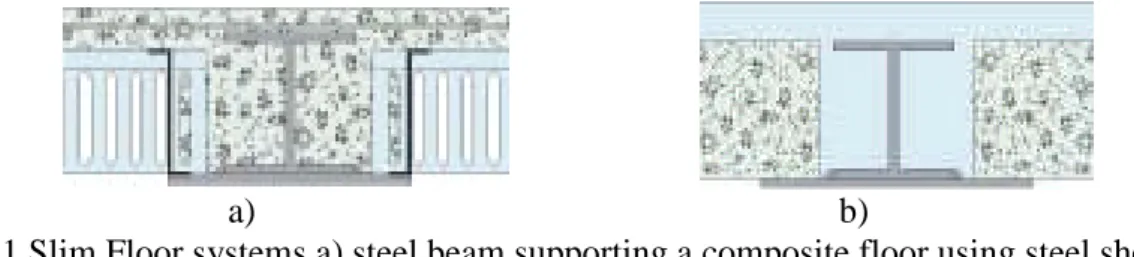
In recent years, increasing interest has been shown throughout Europe in developing and designing Slim Floor systems in steel-framed buildings. The Slim Floor system is a fast, innovative and economical solution which combines prefabricated or casted concrete slabs with built-in steel beams, as shown in Fig. 1. The particular feature of this system is the special kind of girder with a bottom flange which is wider than the upper flange.
Using this arrangement, it is possible to fit the floor slabs directly onto the bottom flange plate of the beam, so that the two constituents thus make up the floor. Additional reinforcement may be provided above the bottom flange, in order to increase the resistance. The result is a reduced height of the slabs and a considerable degree of fire resistance, considering that the steel beam, excepting for the bottom flange, is integrated in the concrete slab.
a) b)
Fig. 1 Slim Floor systems a) steel beam supporting a composite floor using steel sheeting b) steel beam supporting prefabricated elements
To accompany the existing models of Slim Floor systems, ArcelorMittal (ArcelorMittal Commercial Sections) has developed three types of beams which utilize their products. As shown in Fig. 2, IFBs (Integrated Floor Beams) and SFBs (Slim Floor Beams) are built from hot-rolled profiles and welded steel plates. They feature a bottom flange plate which acts as a support for the floor slab. These beams are available for spans up to 8 m and for effective heights of 14 to 30 cm. The length of the bottom flange must guarantee a minimum support on both sides in accordance with the specific requirements of the slab manufacturer.
For the design of this type of floor, the composite action between the casted concrete and the steel beams is usually neglected in the calculation of the plastic design bending moment. The beams may be then calculated as steel elements and not as composite steel-concrete elements. On the other hand, due to the presence of the concrete, the temperatures in the steel beams are not uniform, and a proper temperature distribution should be considered when calculating the fire resistance. The temperature distribution may be determined by a numerical analysis, using an appropriate program. Of course, this must be done for each particular situation, considering the dimensions of the steel beam inside the concrete and of the bottom flange exposed to fire on three sides.
In order to offer to the designer a tool to evaluate the temperatures in a Slim Floor system exposed to ISO fire, without the need of complex numerical simulations, a parametric study was done by the authors, based on numerical simulations using SAFIR program (Franssen, 2005). The aim was to propose a simplified method for the calculation of temperature in relevant points from the cross-section.
1 NUMERICAL MODEL
All the steel profiles presented in the brochure of ArcelorMittal for Slim Floor systems (ArcelorMittal Commercial Sections) were considered in the parametric study. The temperature on each cross-section was analysed with SAFIR and some formulas have been developed, function of different parameters.
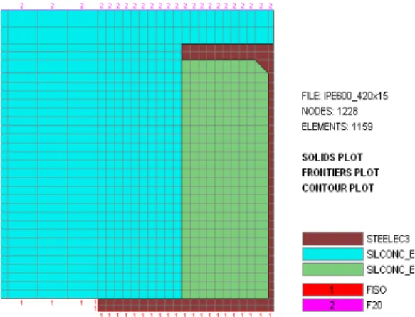
For the thermal analysis, the material properties used in the numerical model (Fig. 3), are those of the Eurocodes for fire design (EN1992-1-2; EN1993-1-2) considering the upper limit of the thermal conductivity for concrete. The cross-section of the beams were exposed to ISO fire for 2 hours from bellow, the temperature in the top of the floor being considered 20οC.
Temperatures from relevant points of the cross-section were extracted from the numerical analysis, and the distance from the top of the bottom flange from which the temperatures are bellow 400o C was also monitored. For all cases, this distance was found on the height of the web, and consequently the temperature in the top plate never reaches 400oC (temperature at which it is considered that the yield strength of steel decreases at elevated temperatures) and the parametric study concentrated further on the temperature distribution on the bottom flange, web and concrete. Fig. 4 shows, as an example, the relevant points considered and the temperature distribution on the cross-section for a given case, after one hour of ISO fire exposure, by highlighting the 400oC limit.
Fig. 3. Discretisation of the cross-section and exposure to fire
Fig. 4. The main analysed points on the cross-section
2 TEMPERATURE IN THE BOTTOM FLANGE
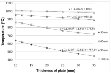
In a first approach, the temperature in the bottom plate was calculated using the simple approach presented in EN1993-1-2, table 4.2, considering the section factor Am/V = (b+2t)/(bt), for the flange exposed on three sides, with concrete floor above the upper flange. Some analyses emphasised that this approach leads to strongly conservative values of the load bearing capacity of the floor, calculated analytically, when compared to the load bearing capacity of the floor calculated numerically, using in the mechanical analysis the proper temperature distribution in the bottom flange. Therefore, in order to obtain conservatives values of the load bearing capacity but closer to reality, for the calculation of the temperature in the bottom plate, another method, was considered. The temperature was monitored for the fire resistance demands of 30, 60, 90 and 120 minutes, in the point from the bottom plate shown in Fig. 4 (at a quarter of the length of the bottom flange). It was emphasized that this temperature depends essentially on the thickness of the bottom plate. Therefore, in order to derive simple formulas for the temperature evolution, the temperatures were represented as shown in Fig. 5, function of the thickness of the plate, for the different fire resistance demands. First and second order functions were found to fit better with the scatter, as Fig. 5 shows.
Fig.5. Temperature in bottom flange function of plate thickness
The following equation is proposed to determine the temperature in the bottom flange, in which Ti is in °C and the plate thickness tplis in mm:
2
i i pl i pl i
T A t B t C (1)
in which the coefficients Ai, Biand Ciare given in Table 1. These coefficients represent the rounded values of the coefficients of the best-fit curves presented in Figure 5, in order to offer „cleanest” values for the designer.
Table 1. Coefficients for temperature calculation in the bottom flange
Time [min] Ai Bi Ci
30 0.113 -12.50 760
60 0.130 -11.80 980
90 - -2.60 990
3 TEMPERATURE IN THE WEB OF THE STEEL PROFILE
The temperature on the height of the web is almost not influenced by its thickness, but is strongly influenced by the distance from the bottom flange and, in a smaller amount, by the thickness of the bottom flange tpl.
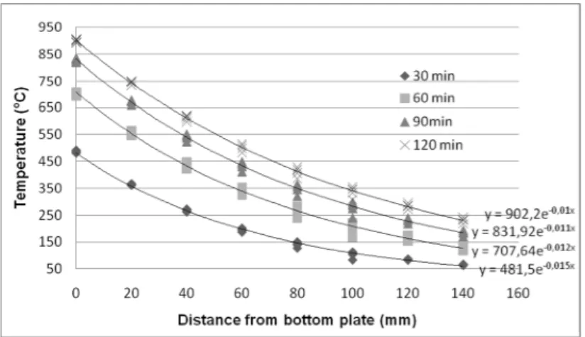
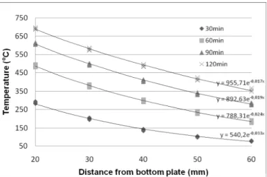
The temperatures were monitored for 30, 60, 90 and 120 minutes in the points from the web shown in Fig. 4. The temperatures were represented as shown in Figure 6, function of the distance from the top of the bottom plate, for the different fire resistance demands and for a given thickness of the bottom plate. Exponential functions were found to fit better with the scatter, as Fig. 6 shows.
Fig. 6. Temperature in web function of height for bottom plate thickness of 12 mm
The following equation is proposed to determine the temperature in the web, in which Tw is in °C, the distance z along the height of the web measured from the top of the bottom flange is in cm and the plate thickness tplis in mm:
2 1 k z w T k e (2) with k1Awln
tpl Bw k2 Cwln
tpl Dwin which the coefficients Aw, Bw, Cwand Dware given in Table 2.
Table 2. Coefficients for temperature calculation in the web
Time [min] Aw Bw Cw Dw
30 -140.70 832.42 0.0317 -0.230
60 -103.80 968.60 0.0232 -0.182
90 -108.60 1146.70 0.0198 -0.154 120 -70.44 1124.40 0.0158 -0.134
4 TEMPERATURE IN THE REBARS ABOVE THE BOTTOM FLANGE
The temperature in the rebars above the bottom flange was considered equal to the temperature of the concrete. As in case of the web temperature, the temperature on the height of the concrete is strongly influenced by the distance from the bottom flange and, in a smaller amount, by the thickness of the bottom flange tpl.
The temperature was monitored for 30, 60, 90 and 120 minutes in the points from the concrete above the bottom flange shown in Fig. 4, which are located in the zone of the possible positions of the rebars. As shown in Fig. 7, the temperatures were represented in a similar manner as for the web
temperature distribution, function of the distance from the top of the bottom plate, for the different fire resistance criteria, for a given thickness of the bottom plate. Exponential functions similar to the ones for web temperature distribution were found for concrete.
Fig. 7. Temperature in concrete function of height for bottom plate thickness of 12 mm The following equation is proposed to determine the temperature in the concrete (rebars), in which
Tc is in °C, the distance z measured from the top of the bottom flange is in cm and the plate thickness tplis in mm : 4 3 k z c T k e (3) with k3 Acln
tpl Bc k4 Ccln
tpl Dcin which the coefficients Ac, Bc, Ccand Dcare given in Table 3.
Table 3. Coefficients for temperature calculation in concrete (rebars)
Time [min] Ac Bc Cc Dc 30 -6.90 612.67 0.0009 -0.342 60 -4.06 834.64 -0.0005 -0.240 90 -2.71 970.63 -0.0005 -0.181 120 -1.37 1043.80 -0.0005 -0.150 CONCLUSIONS
The temperature distribution on the cross-sections of the composite Slim Floor beams subjected to ISO fire was investigated using numerical methods and some simple formulas have been developed for determining the values of temperatures in various points, by means of a parametric study. The temperatures were determined for the bottom flange and the web of the steel profile, and for the concrete, in the zone of the possible positions of the rebars.
Using these formulas, the load bearing capacity of the beams may be calculated, by means of a simple analytical approach, by considering each part of the cross-section that contributes to the load bearing capacity with the corresponding reduced resistance, function of the temperature.
Acknowledgements
This research was made in the frame of a diploma work, supervised in double coordination, within an ERASMUS project between the University of Liege, Belgium, and the „Politehnica” University of Timisoara, Romania.
REFERENCES
ArcelorMittal Commercial Sections, Long Carbon Europe Sections and Merchant Bars, Slim Floor, An innovative concept for floors
Duma D., Simple design method for the fire resistance of composite steel-concrete slim floor systems, T.F.E., Univ. de Liège, 2010
EN 1992-1-2, Eurocode 2 – Design of concrete structures. Part 1-2. General rules – Structural Fire Design, CEN, Brussels, 2005
EN 1993-1-2, Eurocode 3 – Design of steel structures. Part 1-2. General rules – Structural Fire Design, CEN, Brussels, 2005
Franssen J.-M., SAFIR. A Thermal/Structural Program Modelling Structures under Fire, Engineering Journal, A.I.S.C., Vol 42, No. 3 (2005), 143-158, http://hdl.handle.net/2268/2928 PROFILARBED s.a., Groupe Arcelor, CENTRE DE RECHERCHES, Test au feu sur un Plancher