Thin films for applications in generation and
storage of electrical energy
A thesis submitted in partial fulfillment of the requirements for the degree of Doctor of Philosphy (PhD) in Engineering Science
By Chellda EXANTUS
D
OCTORAL COLLEGE INC
HEMICALE
NGINEERINGD
ECEMBER2020
Thin films for applications in generation
and storage of electrical energy
Chellda EXANTUS
Supervisor
Pr. Nathalie JOB
UR Chemical Engineering ULiège - NCE, ULiège
Members of the jury
Pr. Benoît HEINRICHS, President UR Chemical Engineering ULiège – NCE, ULiège Dr. Natacha KRINS LCMCP, Sorbonne University, Paris (France)
Dr. Kévin NADAUD GREMAN UMR 7347 University of Tours, Tours (France) Dr. David ESKENAZI Prayon s.a., Engis
Pr. Bénédicte VERTRUYEN UR CESAM, GREENMAT, ULiège
Remerciements
Ce travail de thèse n’aurait pas pu être réalisé sans la contribution de nombreuses personnes, merci à vous.
J’adresse de sincères remerciements au Pr. Nathalie Job, pour sa grande implication dans la direction de cette thèse, son écoute, sa sincérité, sa disponibilité et surtout son optimisme. Ses encouragements ont été un réel soutien lors des moments difficiles de cette thèse.
J’adresse mes remerciements à Dimitri Liquet, un manager à l’écoute, riche en conseils, et qui a su gérer les difficultés rencontrées lors de ce projet sans y laisser trop de cheveux ;-).
Je remercie Alain Germeau et David Eskenazi, de Prayon s.a., pour leur présence, leur soutien et leurs conseils tout au long de ce projet.
Je remercie également les chercheurs NCE du projet en commençant par Dr. Christelle Alié pour son travail sur la partie « nanogénérateurs ». Je la remercie aussi chaleureusement pour son travail de relecture du manuscrit. Je suis reconnaissante envers Cédric Calberg pour les différents échanges et les dépôts des couches d’électrolytes polymères. J’adresse mes remerciements au Dr. Dorra Dallel pour son travail sur le spray et l’optimisation des dépôts de couches de cathodes mais aussi ses conseils depuis mon arrivée au laboratoire NCE.
J’adresse un remerciement tout particulier au Dr. Carlos Alberto Pàez, dit Beto, devenu bien plus qu’un collègue, pour son travail sur la partie « cathodes », pour sa bonne humeur, son optimisme, ses blagues, ses idées farfelues, mais surtout les conseils depuis mon arrivée au laboratoire NCE.
Je tiens à remercier l’ensemble des membres du jury pour leur évaluation de ce travail : Natacha Krins, Maître de Conférence à Sorbonne Université (Paris), Kévin Nadaud, Maître de Conférence à l’Université de Tours, David Eskenazi, senior research scientist chez Prayon s.a., Bénédicte Vertruyen, Professeure au département de chimie de l’Université de Liège, Christelle Alié, chercheuse senior au département de chemical engineering de l’Université de Liège et Benoît Heinrichs, Professeur au département de chemical engineering de l’Université de Liège.
Aucune caractérisation des nanogénérateurs n’aurait pu être possible sans le laboratoire du GREMAN. Merci au Pr. Guylaine Poulin-Vittrant pour son accueil et au Dr. Kévin Nadaud, de l’Université de Tours, pour les échanges au cours du projet sur la partie montage et caractérisation des nanogénérateurs.
Mes remerciements vont aussi aux membres du laboratoire GreenMat de l’ULiège, notamment la Pr. Bénédicte Vertruyen pour la formation à la DRX et sa confiance, Dr. Catherine Henrist pour la formation ESEM et les échanges, ainsi que le Dr. Pierre Colson pour l’utilisation de l’AFM et les bonbons à la violette. La formation et les conseils du Pr. Philipe Compère, du laboratoire de Morphologie Ultrastructurale de l’ULiège, concernant l’EDX ont également été précieux.
J’adresse également mes remerciements aux membres du CERM de l’ULiège, Charlotte, Martine, Valérie, Charlène, Fabiana, Philip, Raphael et Jérémie pour leur accueil ainsi que l’accès aux mesures de DLS, et la caractérisation par TEM.
Merci à Dirk Poelman Professeur au Lumilab de l’Université de Gand de nous avoir permis de réaliser les mesures de photoluminescence de nos matériaux.
Mes remerciements vont également à Korina et Jérôme, pour le soutien mutuel tout au long de ce projet, les discussions, les gâteaux, et tous les moments passés et à venir.
Je souhaite à présent remercier l’équipe « carbone », les présents et anciens, pour tous les échanges, leur disponibilité, et pour avoir répondu à mes nombreuses questions toutes ces années : Marie-Laure, Anthony, Alexandre, Vaios, Giuseppe, Joe, Aleksandra et Fabien. Mes remerciements vont aussi à l’ensemble du Département de Chemical Engineering. En particulier, merci à Martine, Maria-Rosa et Marlène pour tout le travail administratif, pour leur bonne humeur, pour les différents évènements organisés. Merci à vous, Artium, Carlitos, Céline, Cédric, Polina, Carmenita, Tristan, Julien, Nicolas, Rémi, Antoine, Paul. À vous tous, je vous souhaite le meilleur pour la suite.
Ces quelques lignes sont pour ma mère, mes frères et ma sœur qui m’ont soutenue, encouragée, écoutée, conseillée tout au long de ces études. Un grand merci à Mathieu, qui m’a supportée tout au long de ces études. Je le remercie pour son aide, ses conseils, son soutien et sa motivation.
Résumé
La thèse porte sur le développement de couches minces d’oxydes métalliques par procédé sol-gel, pour des applications diverses. Elle s’inscrit dans le contexte global du projet européen EnSO (Energy for Smart Objects), financé par l’Electronic Components and Systems for European Leadership Joint Undertaking (ECSEL-JTI), en collaboration avec le H2020 Framework Programme (H2020/2014-2020) de l’Union européenne et les autorités nationales. Le projet visait au développement de microsources autonomes d’énergie, comprenant à la fois un système de récupération de l’énergie et un système de stockage. Dans la mesure où le laboratoire NCE de l’ULiège a été impliqué dans le développement des deux parties, et suite à une réorientation générale du projet à mi-parcours, la candidate a été amenée à travailler sur deux types de matériaux différents. La thèse se présente donc en deux parties distinctes. La première partie porte sur l’optimisation d’un procédé de croissance de nanofils d’oxyde de zinc (ZnO), utilisables comme matériau dans un microgénérateur piézoélectrique, en vue de développement industriel. L’objectif a été de mettre au point un procédé de synthèse des nanofils sur substrat, avec des vitesses de croissance compatibles pour une mise à l’échelle industrielle (minimum 20 nm.min-1). Un procédé de synthèse mixte comprenant (i) l’ensemencement du substrat par des nanocristaux de ZnO suivi (ii) de la croissance en milieu liquide a été mis au point. L’étude des différentes étapes du procédé ainsi que de la cinétique de croissance des nanofils a permis d’optimiser les conditions de dépôt et d’obtenir une croissance compatible avec l’échelle industrielle (70 nm.min-1). En combinant les résultats avec ceux obtenus par d’autres chercheurs du projet, il a été possible d’obtenir des matériaux utilisables pour la fabrication de nanogénérateurs piézoélectriques, comme le montrent les caractérisations après montage, en collaboration avec le laboratoire Greman (Tours). Les nanofils ont également été testé comme photocatalyseur pour la décomposition potentielle de polluants dans l’eau, ce qui montre la diversité des applications possibles.
La deuxième partie porte sur l’optimisation de couches poreuses de matériaux d’électrode positive de batterie Li-métal via l’utilisation du Li7La3Zr2O12 (LLZO), un conducteur ionique nanostructuré, synthétisé par voie sol-gel. L’objectif final du projet, réalisé essentiellement en collaboration avec Prayon s.a. et le CEA-Leti (Grenoble), était d’aboutir à des microbatteries Li-métal/LCO tout solide. Le but de cette partie de la thèse, qui se base sur le travail d’un autre chercheur du laboratoire NCE, a été d’améliorer la conductivité ionique des couches d’électrodes positives en remplissant leur porosité de LLZO. Des couches hybrides LCO-LLZO conservant les propriétés électrochimiques du matériau actif d’électrode ont été préparées, et les caractérisations effectuées en ajoutant un électrolyte liquide montrent que le LCO ne subit aucune altération en présence de LLZO. Enfin, des résultats préliminaires encourageants ont été obtenus en remplaçant l’électrolyte liquide par un électrolyte solide polymère (Gel Polymer Electrolyte) développé au NCE : l’ajout de LLZO à l’électrode de LCO a permis d’obtenir une microbatterie qui cycle de manière stable à une vitesse de 1C. Mots clés : nanofils de ZnO, nanogénérateur, couches minces, LiCoO2, LLZO, microbatteries solide.
Abstract
The PhD was focused on the development of metal oxides thin films using sol-gel process, for various applications. It is part of the overall context of the European EnSO (Energy for Smart Objects) project, funded by the Electronic Components and Systems for European Leadership Joint Undertaking (ECSEL-JTI), in collaboration with the European Union's H2020 Framework Programme (H2020/2014-2020) and national authorities. The project aimed at developing autonomous micro energy sources, including both an energy harvesting system and a storage system. As the ULiège NCE laboratory was involved in the development of both parts, and following a general reorientation of the project at mid-term, the candidate was led to work on two different types of materials. This PhD thesis is thus presented in two distinct parts.
The first part concerns the optimisation of a process for the growth of zinc oxide nanowires (ZnO NWs) for piezoelectric nanogenerator application. The objective was to develop a process for the synthesis of NWs on a substrate, with a growth rate compatible for industrial scale-up (minimum 20 nm min-1). A combined process including (i) the deposition of a seed layer made of ZnO crystallites followed by (ii) ZnO NW growth using wet chemistry was developed at the NCE laboratory. The study of the different steps of the process, as well as the growth kinetics of the NWs, made it possible to optimise the conditions of deposition and to obtain a growth speed compatible with industrial scale (70 nm min-1). By combining the results with those obtained by other researchers in the project, it was possible to obtain materials that can be used for the manufacture of piezoelectric nanogenerators, as shown by the characterisations after assembly, in collaboration with the Greman laboratory (Tours). The NWs were also characterised as photocatalysts for the potential decomposition of pollutants in water, thus showing the diversity of possible applications.
The second part focuses on the optimisation of porous layers for positive electrodes of Li-metal batteries. Optimisation was based on the use of Li7La3Zr2O12 (LLZO), an ionic conductor synthesised by sol-gel process, as nanostructured solid electrolyte within the electrode. The final objective of the project, carried out mainly in collaboration with Prayon s.a. and CEA-Leti (Grenoble), was to produce solid-state Li-metal/LCO microbatteries. The aim of the thesis, which is based on the work of another researcher from the NCE laboratory, was to improve the ionic conductivity of the positive electrode layers by filling their porosity with the nanostructured LLZO. Hybrid LCO-LLZO layers preserving the electrochemical properties of the active electrode material were prepared and the characterisations carried out by adding a liquid electrolyte showed that the LCO does not undergo any alteration in the presence of LLZO. Finally, preliminary encouraging results were obtained when replacing the liquid electrolyte with the gel polymer electrolyte (GPE) developed at NCE: the addition of LLZO to the LCO electrode resulted in a microbattery that is stable when cycling at 1C. Keywords: ZnO nanowires, nanogenerator, thin films, LiCoO2, LLZO, solid-state microbattery.
Table of contents
General introduction ... 1
Chapter 1. Kinetic optimisation of zinc oxide nanowire growth ... 10
1.1 Introduction ... 10
1.2 Experimental ... 13
Reproduction of growth procedure from Kokotov et al. [25] ... 13
Modification of the growth procedure from Kokotov et al. [25] ... 15
Growth kinetics study ... 16
Optimisation of the NW growth process from the kinetics study ... 17
Homogeneity of the temperature ... 17
1.3 Results and discussion ... 18
Reproduction of growth procedure from Kokotov et al. [25] ... 18
Simplification of the growth procedure from Kokotov et al. [25] ... 19
Growth kinetics study ... 21
1.3.3.1 Study of the growth process ... 21
1.3.3.2 Kinetics study ... 28
1.3.3.3 Reproducibility of the kinetic study ... 34
Optimisation from the kinetic study ... 36
Homogeneity of the temperature ... 37
1.4 Conclusion ... 39
Chapter 2. Optimisation of the seed layer ... 44
2.1 Introduction ... 44
2.2 Experimental work ... 47
2.2.1. Cleaning procedure ... 47
2.2.2. Seed deposition by spin-coating vs. dip-coating ... 47
2.2.2.1. Seed deposition by spin-coating ... 47
2.2.3. Influence of Zn(CH3COO)2 concentration on the seed layer ... 49
2.2.4. Effect of seed layer calcined at different temperature ... 50
2.2.5. Influence of the number of seed layers ... 51
2.2.6. Influence of the calcination procedure of the seed layer ... 52
2.2.7. Growth of NWs ... 54
2.2.7.1. Optimised growth process using zinc sulphate ... 54
2.2.7.2. Modified growth process using zinc nitrate and zinc sulphate ... 55
2.3. Results and Discussion ... 55
2.3.1. Cleaning procedure ... 55
2.3.2. Seed layer by spin coating vs. dip coating... 56
2.3.3. Influence of Zn(CH3COO)2) concentration on the seed layer ... 58
2.3.4. Influence of the calcination temperature of the seed layer ... 61
2.3.5. Influence of the number of layers ... 65
2.3.6. Influence of the calcination procedure on the seed layer ... 70
2.3.7. NW growth process using zinc nitrate and zinc sulphate ... 73
2.4. Conclusions ... 74
Chapter 3. Applications of ZnO nanowires ... 79
3.1 Introduction ... 79
3.2 ZnO NWs as nanogenerators ... 80
3.2.1 Introduction ... 80
3.2.2 Experimental part ... 86
3.2.2.1 ZnO NWs ... 86
3.2.2.1.1 Preparation of the substrates ... 86
3.2.2.1.2 Seed layer deposition ... 86
3.2.2.1.3 NW growth ... 86
3.2.2.2 Nanogenerator assembly ... 87
3.2.3 Results and discussion ... 91
3.2.3.1 ZnO NW ... 91
3.2.3.2 NG assembly ... 94
3.2.3.3 NG characterisation... 95
3.2.3.4 Improvement of the NG performances. ... 97
3.2.4 Conclusion ... 98
3.3 ZnO NWs as photocatalyst ... 99
3.3.1 Introduction ... 99
3.3.2 Experimental work ... 101
3.3.2.1 ZnO NWs for the photocatalytic decomposition of H2O2... 101
3.3.2.1.1 Seed deposition ... 101
3.3.2.1.2 Growth or ZnO NWs ... 101
3.3.2.2 Measurement of the photocatalytic activity for the decomposition of H2O2 .. ... 102
3.3.3 Results and discussion ... 104
3.3.3.1 ZnO NWs physical characterisation ... 104
3.3.3.2 Photocatalytic activity of the ZnO NWS ... 105
3.3.4 Conclusion ... 109
3.4 Conclusion ... 110
Chapter 4. Optimisation of LiCoO2 cathode material using Li7La3Zr2O12 ... 115
4.1 Introduction ... 115
4.2 Experimental work ... 120
4.2.1 Synthesis and physico-chemical characterisation of LT-cubic LLZO ... 120
4.2.2 Preparation of the LCO suspensions ... 122
4.2.2.1 LCO suspension in water ... 122
4.2.2.2 LCO suspension in ethanol ... 122
4.2.3.1 LLZO deposition ... 123
4.2.3.2 Deposition of LCO and LCOTiO2 suspensions ... 124
4.2.3.3 Deposition of LCOTiO2 + LLZO suspension ... 124
4.2.4 Electrochemical characterisation ... 126
4.2.4.1 Set-up for LLZO characterisation ... 126
4.2.4.2 LCO characterisation set-up... 127
4.2.4.3 LCOTiO2 + LLZO characterisation set-up ... 127
4.3 Results and discussion ... 128
4.3.1 Synthesis and physico-chemical characterisation of the LT-cubic LLZO ... 128
4.3.2 Preparation of LCO suspensions ... 131
4.3.2.1 LCO suspension in water vs. LCOTiO2 in ethanol ... 131
4.3.2.2 Preparation of LCO-LLZO suspension ... 132
4.3.3 Electrode preparation ... 132
4.3.3.1 Pure LLZO ... 132
4.3.3.2 LCOTiO2-LLZO ... 133
4.3.4 Electrochemical measurements ... 135
4.3.4.1 Characterisation of LLZO ... 135
4.3.4.2 Characterisation of LCO coatings prepared in water vs. ethanol ... 136
4.3.4.3 Characterisation of LCOTiO2 coatings by cyclic voltammetry ... 137
4.3.4.4 Characterisation of LCOTiO2 + LLZO coatings ... 138
4.4 Conclusion ... 143
Combination of the optimised LCOTiO2/LLZO cathode material with GPE electrolyte ... 147
Introduction ... 147
Experimental ... 149
Preparation of LCOTiO2 and LLZO suspension ... 149
LLZO ... 149
LCO with LLZO ... 150
Synthesis and deposition of gel polymer electrolyte ... 150
Characterisation set-up ... 151
LLZO characterisation set-up ... 151
LCOTiO2 + LLZO characterisation set-up ... 152
Electrochemical characterisation ... 152
Results and discussion ... 153
Conclusion ... 156
1
General introduction
Context of the thesis
The development of the wearable electronic technologies such as wireless sensors networks (WSN) based equipment is evolving quickly. The WSN technologies enable ultra-fast and reliable communication as well as data transfer. This field of research has attracted much attention of researchers and industry experts in the areas of industrial automation [1], health care, internet-of-things (IoT) [2], etc. IoT, is a concept where everyday objects will be able to communicate together via internet to enhance their efficiency upon use; it is nowadays gaining more and more attention within the electronics industry. As an example, Figure 1 shows dynamic cryptogram for bank card developed by Gemalto in order to reinforce payment security.
Figure 1. Gemalto dynamic cryptogram developed for BNP.
All these “smart objects” have to be autonomous, easy to use and handle, as small as possible, robust and long lasting with a long operating lifetime. The key component for all electronic systems is the energy supplier: how to harvest, store and use energy? To answer this question, it is necessary to combine different devices: (i) an energy harvester, which is able to capture energy from the environment and, possibly, transform it into electrical energy, (ii) a storage system, able to keep this energy available for a sufficient long time and (iii) electronics for energy management upon storage and use.
In this context, the Energy for Smart Object project (EnSO) [3] was accepted for financing within the Electronic Components and Systems for European Leadership Joint Undertaking (ECSEL-JTI), in collaboration with the European Union's H2020 Framework Programme (H2020/2014-2020) and National Authorities. The project was managed by ST Microelectronics in collaboration between 35 European partners, among which (i) 8 academic research partners, (ii) 5 supply chain companies, (iii) 4 integrated device manufacturers and
2 (iv) 15 end-users. It started in 2016 and was focusing on providing Autonomous Micro Energy Sources (AMES) to end-users. AMES would at least consist of three elements:
(i) An energy harvester, i.e. a nano energy generator, which converts energy from the environment into electricity;
(ii) A battery as micro energy storage system; (iii) A battery management system.
Within this framework, the Nanomaterials, Catalysis and Electrochemistry (NCE) laboratory of the University of Liège was involved (i) in the development of materials to be integrated in energy harvesters, in collaboration with the Greman laboratory in Tours (France) and (ii) in the development of layers of active materials for microbatteries as energy storage systems, in collaboration with Prayon s.a. and the Commissariat à l’Energie Atomique et aux Energies Alternatives (CEA-Leti), located in Grenoble (France). Throughout the years, 3 post-doctoral researchers, 2 research engineers and 2 PhD students were involved in the research performed at the NCE laboratory in the framework of the EnSO project.
Figure 2. Scheme of an AMES using energy harvester.
Energy harvesters
The development of energy harvesters was focused on the use of a piezoelectric system. The global objective was to develop a piezoelectric nanogenerator (Figure 3) based on zinc oxide nanowires (ZnO NWs), in collaboration with the Greman laboratory. The latter had already developed a strong expertise on such energy harvesters [4, 5]. While the NCE was in charge of developing a ZnO NW synthesis process compatible with scale-up, the Greman laboratory dedicated the effort to the encapsulation of the ZnO NWs into complete piezoelectric devices and to their characterisation (electrical response to mechanical solicitation).
3
Figure 3. Principle of piezoelectric nanogenerator.
Piezoelectric materials such as ZnO NWs exhibit an induced voltage under applied stress (Figure 3). According to the EnSO project specifications, high crystalline quality ZnO NWs should be synthesised using a low temperature process (< 400 °C) so that the NWs can ultimately be deposited onto flexible organic substrates. In addition, the developed process needs to be suitable for large-scale manufacturing, meaning that the growth speed of the NWs should reach 20 nm min-1 while keeping the process as simple as possible. Finally, the obtained micrometric layer should be composed of well-aligned and well-crystallised NWs, able to power a Li-metal microbattery system by providing a power of the order of 1 μW cm-2 at a voltage of 4.2 V.
The growth of ZnO NWs usually requires the pre-deposition of a seed layer onto which NWs are grown [6–8]. In that perspective, sol-gel processes were used and optimised to develop both the seed layer and the NWs. Two researchers of the NCE laboratory were involved in the research program: one PhD student (Chellda Exantus) and one senior researcher (Dr Christelle Alié). Thus, the results presented here are a part of the global research program performed at the NCE laboratory during the project. Since both researchers worked in parallel, results obtained by one could fed the other’s work part, and results are thus much intricate. For that reason, it was necessary to include in this manuscript some of the experiments and results obtained by the senior researcher in order to understand the evolution of the research program and to show the outcome of the project. Throughout the thesis
4 manuscript, the respective contributions of the PhD student and the senior researcher were highlighted at best.
Microbatteries
Regarding microbatteries, the NCE laboratory was in charge of developing two components for Li-metal systems: LiCoO2 (LCO) electrodes and solid electrolyte, either full Solid-State Electrolyte (SSE) or Gel Polymer Electrolyte (GPE). Both layers had to be deposited via spray-coating, in order to replace the costly Physical Vapor Deposition (PVD) processes used by the initial leader of the project, ST Microelectronics. The final objective was to build a full-solid Li-metal microbattery with high energy density, using spray-coating for the deposition of the positive electrode material and the electrolyte. According to the objectives of the EnSO project, the battery should be rechargeable, display a long-life time (> 10 years), and reach a capacity of 3 mAh.
The development of the lithium metal microbatteries was made in collaboration with the CEA-Leti laboratory, as they already had developed materials for thin film batteries, and with Prayon s.a., from the supply chain. Indeed, the NCE laboratory expertise on microbatteries had been previously developed within the framework of a large project co-financed by Wallonia and Prayon s.a. [9]. During that previous project, a senior researcher of the NCE laboratory, Dr Carlos Páez, had developed a low-cost process for the deposition of thin layers of lithium cobalt oxide (LCO) cathode material for Li metal microbatteries [10]. This process uses spray-coating and allows the deposition of 10-µm thick LCO layer. The final battery, assembled in coin-cell with liquid electrolyte in-between Li metal anode and LCO cathode, displayed a capacity of 1 mAh. The challenge here was to replace the liquid electrolyte by an SSE (Lithium Phosphorous Oxynitride, LiPON) or a GPE, in order to get rid of the volatile, flammable liquid electrolyte incompatible with the final application in (flexible) microbatteries. The main issue is the porosity in the cathode coating (~50-60%): while liquid electrolyte easily enters the porosity and allows for easy ion transport through the whole electrode thickness, GPE or SSE are much harder to use since they are normally deposited on top of the electrode. The migration of the lithium ions is thus hindered, which leads to the decrease of the ionic conductivity, and a drop of the battery capacity. It was thus necessary to modify the LCO deposition process so as to include a solid electrolyte within the pore texture of the electrode material layer. In addition, the rugosity of the LCO layer was originally too high for SSE deposition; it had thus to be improved to be compatible with LiPON. Ultimately,
5 the modified LCO layer was to be combined with an SSE or a GPE, and embedded in a full solid-state battery.
Figure 4. Example of microbattery developed during EnSO project.
At the beginning of the EnSO project, research on microbatteries was essentially conducted by two senior researchers of the NCE laboratory: Dr Carlos Páez for the development of modified LCO coatings onto substrates provided by the CEA, and Cédric Calberg for the deposition of GPE onto the electrodes. However, after 2 years, the EnSO project was reorganised and it was decided to reduce the resources allocated to the development of the piezoelectric nanogenerators in order to reinforce the microbattery topic. For that reason, Chellda Exantus joined the microbattery team, and contributed to the development of the modified LCO layer using sol-gel processes.
Even though the subject seems a priori quite different from that of the ZnO NWs for piezoelectric generator, it lies on the same competences and techniques. In both cases, the goal was to manufacture thin solid films of materials using sol-gel processes and deposition techniques, and to characterise them by physico-chemical and electrochemical techniques. The apparent constraint of subject change, in the middle of the thesis, was thus an opportunity to develop similar ideas and methods in two different environments.
Objectives of the thesis
As explained above, this thesis was part of a large European project dealing with the manufacturing of complete Autonomous Micro Energy Sources (AMES). The general goal of
6 the thesis was to contribute to the development of AMES by designing innovative techniques to prepare thin layers of materials onto a substrate. The general requirement was that the methods used could be transferred to industrial scale; they had to be cheap, easy to handle, fast, reproducible and require as less energy as possible. Material preparation was thus performed by sol-gel techniques, and the processes were studied so that the required post-treatment temperatures, necessary whatever the material considered, were as low as possible. As the project evolved throughout the years, two distinct topics with their own goals were studied:
- The optimisation of ZnO NW preparation, including the seeding and the growth steps, in order to obtain NW arrays that could be used in piezoelectric nanogenerators; - The modification of LiCoO2 (LCO) coatings so that they could be used as cathode
layers in full solid-state microbatteries.
Structure of the thesis
The thesis is divided into two main parts. The first one, including Chapters 1 to 3, deals with the development of the ZnO NW manufacturing process and their use in practical applications. The second one, corresponding to Chapters 4 and 5, reports the contribution to the modification of the LCO cathode layers in Li-metal microbatteries, and their combination with a GPE.
In Chapter 1, we report a simple process to manufacture a homogeneous arrangement of flat ended hexagonal ZnO NWs, well aligned along the c-axis through a chemical bath deposition (CBD) method. The process developed needed to be suitable for large-scale manufacturing (i.e. minimum 20 nm min-1 growth speed), and to provide a micrometric layer of well-aligned NWs. In order to meet this expectation, a previously published synthesis method [11, 12] was optimised for growing the ZnO NWs. Before growth, a uniform ZnO seed layer was deposited on the substrate by combining a simple low-cost sol-gel process and a spin-coating technique. The obtained materials were observed by environmental scanning electron microscopy (ESEM) to measure the NW length and diameter. This allowed to study the NW growth kinetics in order to identify the critical process variables, i.e. those that have an impact on the synthesis process.
In Chapter 2, an original seed method using dip-coating was developed in order to orientate the growth of ZnO crystals. Indeed, the seed layer characteristics (crystallinity, orientation, thickness) has a strong influence on the NW growth. The cleaning of the substrate, the deposition method and the subsequent thermal treatment were studied to determine their
7 impact on the seed quality and, further, on the length, diameter and orientation of the final NWs obtained by CBD. In parallel to the seed study, the senior researcher involved in the topic, Dr Christelle Alié, worked on the optimisation of the NW growth in order to obtain, in fine, separate and well-aligned NWs.
In Chapter 3, the work was focused on the use of the obtained NWs in two applications. First, in collaboration with the Greman laboratory, ZnO NWs were implemented into piezoelectric nanogenerators. This application requires the use of well-aligned NWs without crystalline defects (vacancies, interstitials elements), which is very difficult by CBD process. The presence of these defects generates free electrons that can mask the piezoelectric charges and thus reduce the performance of the NG [13, 14]. To point out the impact of the research on a global scale, the chapter thus also summarises the parallel work of the senior researcher (Dr Christelle Alié), aiming at decreasing the concentration of defects and improving the nanogenerator performances. Second, as the NCE laboratory also works on photocatalysts for water depollution, a first trial of ZnO NWs as photocatalyst was performed: the catalytic activity of ZnO NWs deposited on glass for the photoctalytic degradation of hydrogen peroxide was evaluated. Both examples point towards the necessity to control at best the NW growth so as to obtain structures compatible with the final chosen application.
Switching from ZnO NWs to microbatteries, Chapter 4 was dedicated to the synthesis and characterisation of low temperature cubic Li7La3Zr2O12 (LLZO), and its insertion into the LCO cathode coating. Indeed, in order to obtain Li+-conducting LCO layers, it is necessary to fill the layer porosity (~50-60%) with a solid electrolyte to finally be able to build an all solid-state battery. LLZO nanoparticles could be obtained and mixed with the LCO suspension before electrode deposition by spray-coating, following the electrode development performed by Dr Carlos Páez within the EnSO project. Different LLZO amounts were added, and the mixture stability upon cycling in a battery configuration was assessed, still using liquid electrolyte. This step was necessary to make sure that no side-reaction could occur between the two electrode components.
Finally, in Chapter 5, the optimised cathode material containing LCO and LLZO was combined with a Gel Polymer Electrolyte developed at the NCE laboratory by Cédric Calberg. It was possible to characterise the full solid-state battery and show the impact of LLZO on the final performances upon cycling.
8
References
1. D. Christin, P. S. Mogre, M. Hollick, Survey on Wireless Sensor Network Technologies for Industrial Automation: The Security and Quality of Service Perspectives. Futur. Internet 2, 96–125 (2010).
2. N. Khalil, M. R. Abid, D. Benhaddou, M. Gerndt, in IEEE ISSNIP 2014 - 2014 IEEE 9th International Conference on Intelligent Sensors, Sensor Networks and Information Processing, Conference Proceedings (2014), pp. 1–6.
3. Energy for Smart Objects (EnSO), EnSO, http://www.enso-ecsel.eu, grant agreement n° 692482, 2016-2020.
4. K. Nadaud, F. Morini, A. S. Dahiya, C. Justeau, S. Boubenia, K. P. Rajeev, D. Alquier, G. Poulin-Vittrant, Double buffer circuit for the characterization of piezoelectric nanogenerators based on ZnO nanowires. Appl. Phys. Lett. 112, 1–6 (2018).
5. A. S. Dahiya, F. Morini, S. Boubenia, K. Nadaud, D. Alquier, G. Poulin-Vittrant, Organic/Inorganic hybrid stretchable piezoelectric nanogenerators for self-powered wearable electronics. Adv. Mater. Technol. 3, 1–11 (2018).
6. Y. H. Kang, C. G. Choi, Y. S. Kim, J. K. Kim, Influence of seed layers on the vertical growth of ZnO nanowires. Mater. Lett. 63, 679–682 (2009).
7. J. Song, S. Lim, Effect of seed layer on the growth of ZnO nanorods. J. Phys. Chem. C.
111, 596–600 (2007).
8. L. E. Greene, M. Law, D. H. Tan, M. Montano, J. Goldberger, G. Somorjai, P. Yang, General route to vertical ZnO nanowire arrays using textured ZnO seeds. Nano Lett. 5, 1231–1236 (2005).
9. Programmes d'Excellence en Partenariat Public Privé – PHOSPHAGEL: "Synthèse par procédé sol-gel de matériaux pour microbatteries en couches minces". Grant No. 0917013, 2009 - 2015.
10. C. A. Páez Martínez, C. Exantus, D. Dallel, C. Alié, C. Calberg, D. Liquet, D. Eskenazi, F. Deschamps, N. Job, B. Heinrichs, Water-based paintable LiCoO2 microelectrodes: a high-rate Li-ion battery free of conductive and binder additives. Adv. Mater. Technol. 4, 1–12 (2019).
11. M. Kokotov, A. Biller, G. Hodes, Reproducible chemical bath deposition of ZnO by a one-step method: The importance of “contaminants” in nucleation. Chem. Mater. 20, 4542–4544 (2008).
9 12. M. Kokotov, G. Hodes, Reliable chemical bath deposition of ZnO films with controllable morphology from ethanolamine-based solutions using KMnO4 substrate activation. J. Mater. Chem. 19, 3847–3854 (2009).
13. S. Xu, Z. L. Wang, One-dimensional ZnO nanostructures: Solution growth and functional properties. Nano Res. 4, 1013–1098 (2011).
14. D. A. Scrymgeour, J. W. P. Hsu, Correlated piezoelectric and electrical properties in individual ZnO nanorods. Nano Lett. 9, 2204–2209 (2008).
10
Chapter 1.
Kinetic optimisation of zinc oxide nanowire
growth
1.1 Introduction
The scavenging of ambient energy for its subsequent exploitation has become a hot research topic in the last few years [1–7]. Energy harvesting relies on a transduction force that converts the ambient mechanical energy into electricity. This mechanical energy can have different forms such as vibrations, random motions or noise, and one of the most common transduction method takes advantage of the piezoelectric effect [8]. A piezoelectric material has the peculiarity of creating an inherent electric field when strained (direct piezoelectric effect). There are several well-known piezoelectric materials [8, 9] with a broad range of applications (e.g. AlN, lead zirconate titanate (PZT), ZnO, quartz, etc.). However, among them, ZnO has become very popular in material science over the past few years because of its wide variety of nanostructures and its dual property of being both a semiconducting and a piezoelectric material [10]. One of the most useful nanostructures that can be utilised to generate energy is the nanowire (NW). The piezoelectric properties of ZnO are linked to its crystalline asymmetry, which leads to a change in the position of atoms during deformation, and induces the appearance of an electrical dipole along the nanowire. The semiconductor property of ZnO contributes to the formation of a low current electrical potential, and allows the supply of microbattery storage systems.
11
Figure 1.1. Preferential growth of ZnO NWs along 002 axis (c-axis). Reproduced from [11].
In order to limit the recombination of piezoelectric charges between NWs, it is required that the NWs are well aligned along the c-axis (002) (Figure 1.1) [11]. Hinchet et al., showed that thin and long hexagonal flat ended shape NWs improve the piezoelectric performances [12, 13].
In the literature, one can find numerous bottom-up approaches to grow ZnO nanostructures, such as vapor-solid and vapor-liquid-solid processes (vacuum processes consisting in the reaction of precursors in a vapor phase and their deposition on a substrate surface) or electrochemical deposition (process that uses oxidation and reduction of one material onto the surface of another material through an electric current) [14–17]. However, these methods require high temperatures (400-700 °C) and low pressures (10-20 Pa), conductive substrates, or acid-resistant environments that make them difficult to be integrated into standard fabrication processes and future flexible electronics. In order to make the growth process of ZnO nanostructures more energy efficient and cost-effective, the temperature of the process should ideally be reduced below 100 °C. Hence, the chemical bath deposition (CBD) of ZnO is attractive and widespread due to its simplicity and environmentally friendly conditions. The CBD works on the principle of the controlled nucleation of the desired compound from a solution of its constituents, followed by a growth of the nucleus on a substrate and the formation of thin films.
To grow ZnO NWs, a crystalline material with similar crystallographic lattice constants (a = b = 0.325 nm; c = 0.520 nm) is the best choice in order to obtain aligned and high-quality NWs
12 [18]. Thus, NWs can be grown directly by using materials such as gold (a = b = c = 0.408 nm), wurtzite gallium nitride (a = b = 0.319 nm; c = 0.518 nm), sapphire (a = b = 0.480; c = 1.310 nm), where vertical growth only is observed. Another way to grow ZnO NWs is the deposition of a layer of zinc oxide nanoparticles using ZnO or zinc acetate, called seed layer, before the growth of ZnO NWs. This layer allows the deposition of ZnO NWs on a wide range of substrates, as the growth and proper orientation of the NWs are triggered by the seed nanoparticles [18–21]. The quality of the seed layer, offering adequate nucleation sites for ZnO growth, is a key factor for obtaining well-oriented and homogeneous NWs arrays [22, 23].
The classical solution-based CBD synthesis leads to epitaxial growth of ZnO nanostructures in aqueous solution in the presence of zinc nitrate and hexamethylenetetramine (hexamine) as precursor materials at temperatures lower than 100 °C. The major drawback in the CBD method is the slowness of the growth process: in some cases, reaching the appropriate length for the ZnO (a few µm) requires a time of about 10-30 h (growth rate between 2-7 nm min-1) and the substrates must be placed into fresh growth solutions repeatedly [24]. The very large extent of homogeneous nucleation (formation of ZnO in the solution) in comparison with heterogeneous nucleation or heteronucleation (formation of ZnO on the seeded substrate) is the main reason for this problem [25]. Heterogeneous nucleation leads to the consumption of the precursor materials necessary to grow ZnO NWs on the substrate. The result of the homogeneous nucleation is ZnO settlement at the bottom of the solution container which leads to a loss of the majority of the precursor materials and reduction of the NW growth. Several methods have been suggested in order to increase the growth rate of ZnO NWs grown by CBD. It is possible to reduce the time needed to grow NWs by using a microwave-assisted solution-based method; this aims at accelerating the crystal growth via a rapid increase of the precursor solution temperature [26]. The main disadvantage of the microwave-assisted CBD method is that it increases both the heterogeneous and the homogeneous process rates and, thus, the loss of the precursor materials would be faster as well. Another method implemented for increasing the ZnO NWs growth rate is called the preferential growth [27]. This method involves the addition of ammonium hydroxide and polyethylenimine (PEI) to the precursor solution. In the presence of both PEI and ammonium hydroxide, formation of ZnO in the bulk solution can be effectively prevented while ZnO wires still grow on the seeded substrate at a reasonably high rate. Furthermore, PEI preferentially adsorbs onto ZnO NWs lateral faces, thus inhibiting radial growth in favour of axial growth. This results in longer and thinner NWs, a morphology that is favourable for high piezoelectric performances [28, 29]. Kokotov
13 et al. deposited ZnO NWs using an amino acid-induced self-assembly strategy [25]. The substrate was activated by a simple potassium permanganate solution treatment that forms Mn-(hydroxy)-oxide deposits on the surface; these deposits act as an efficient seed layer. In small vials (10 mL), 5 µm long NWs could be grown in 40 min (i.e. 125 nm min-1), which is very fast compared to most processes [30].
The objective is to grow well aligned and separated NWs with an aspect ratio (Length/Diameter) higher than 50, with a flat ended hexagonal shape.
Here we report a simple process to manufacture a homogeneous arrangement of flat ended hexagonal ZnO NWs, well aligned along the c-axis through a chemical bath deposition (CBD) method. The process developed in the present work needs to be suitable for large-scale manufacturing (i.e. minimum 20 nm min-1 growth speed), and to provide a micrometric layer of well-aligned NWs. To that aim, Kokotov’s synthesis process [31, 32] was optimised for growing the ZnO NWs. Before the CBD, a uniform ZnO seed layer was first prepared on the substrate by combining a simple low-cost sol-gel process and a spin-coating technique. A ZnO seed layer was preferred to permanganate activation of the substrate, as the latter technique leads to NWs arrays with poor homogeneity over large substrate. To ensure a suitable growth speed, a kinetic study was completed by controlling the parameters that have an impact on the synthesis and coating process. Finally, the obtained materials were characterised by environmental scanning electron microscopy (ESEM) to measure length and diameter.
1.2 Experimental
The de-ionised (DI) water used in all experiments was prepared in a Purelab Flex purification system (Elga LabWater) and had a resistivity of 18.2 MΩ cm. ZnO NWs were grown by chemical bath deposition (CBD) onto glass microscope slides (Superior Marienfeld) according to the following procedures.
Reproduction of growth procedure from Kokotov et al. [25]
All substrates were first cleaned by sonication in an RBS T105 detergent solution (20 min) and rinsed by dipping the substrate in deionised water (20 min), acetone (20 min) and ethanol (20 min). They were then dried in air for 30 min at 60 °C.
14 Two preparations of the seed layer were studied. The first procedure consisted in the activation of the substrate by dipping the substrates 30 min at 85 °C into a 0.5 mol L-1 solution of potassium permanganate (KMnO4, ≥ 99.0%, Sigma Aldrich) into which 50 µL of n-butanol (≥ 99.0%, Sigma Aldrich) per 20 mL of the permanganate solution were added (as a reducing agent for the KMnO4). Permanganate-treated substrates were extensively rinsed in DI water (the vials containing the samples were filled with DI, which was then poured out, and this was repeated for a total of 10 rinses) and then sonicated 5-10 min in DI water in an ultrasonic bath [31]. The second procedure consisted in the preparation of a solution in ethanol of zinc acetate dihydrate (Zn(CH3COO)2.2H2O, Sigma Aldrich, 99.9%) with a concentration of 5 × 10- 3 mol L -1. 1 mL of the solution was deposited onto a clean microscope slide substrate via the spin-coating technique. The spin coating was performed at 2000 rpm for 30 s; the whole process was repeated 5 times. Finally, calcination at 350 °C for 20 min was performed in order to decompose zinc acetate into ZnO nanocrystals which would act as nucleation sites for the subsequent growth of ZnO NWs.
After the ZnO seed layer deposition, ZnO NWs were grown by CBD. According to Kokotov et al. [31, 32], growth solutions were prepared using the following freshly prepared aqueous solutions: 1.0 mol L-1 zinc sulphate heptahydrate (ZnSO4.7H2O, 99%, Sigma Aldrich), 4.0 mol L-1 ammonium hydroxide (ammonium hydroxide water solution, NH4OH, 25-30 wt.% as ammonia (NH3), Emsure, Merck) and 50% v/v ethanolamine (2-aminoethanol, ≥ 98%, Sigma Aldrich). As the ammonium hydroxide concentration varies when reagent bottles are gradually consumed, the ammonium hydroxide solution was systematically titrated before the synthesis. The final growth solution was prepared from the stock solutions in a 160 mL polypropylene vial, by sequential addition of 13 mL of zinc salt solution, 19.5 mL of ammonia solution and 26 mL of ethanolamine solution to DI water, giving the following final concentrations: 0.1 mol L-1 Zn2+, 0.6 mol L-1 NH4OH and 1.7 mol L-1 ethanolamine. The amount of water was chosen so that the total volume of growth solution was 130 mL. The final pH was typically 11.1 0.2. During growth, the ZnO particles formed in solution (homogeneous nucleation) can settle on the substrate. That is the reason why, immediately after preparation of the solution, the substrate was introduced inclined from vertical with the seeded side facing downwards. The reaction vial was closed and placed in an oil bath at 90 °C for 2 h. After growth, the substrate was removed from the solution, immediately rinsed with DI water to remove loose ZnO precipitates and any residual reactant from the surface, and dried in air at room temperature for 24 h. After growth, the diameter and length of the NWs
15 were measured from environmental scanning electron microscopy (ESEM-FEG XL30 Philips, Esprit 1.9 software) images.
Modification of the growth procedure from Kokotov et al. [25]
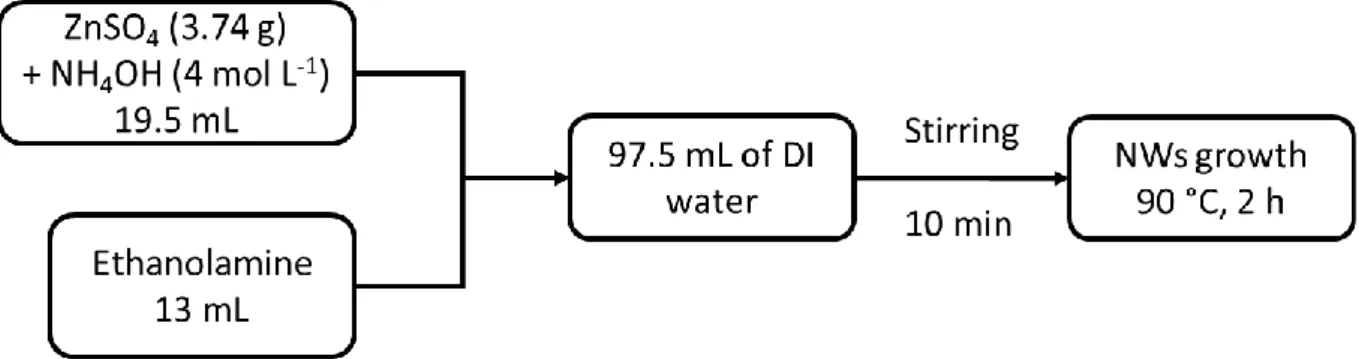
The ZnO NWs growth procedure was optimised for scaling-up by simplifying the preparation of the growth solution: the ZnSO4 powder (3.74 g) was directly dissolved into 19.5 mL of 4.0 mol L-1 NH4OH solution. The previous solution and 13 mL of ethanolamine were added to 97.5 mL of DI water. The growth solution (130 mL) was prepared in a 160 mL polypropylene vial, giving the following final concentrations: 0.1 mol L-1 Zn2+, 0.6 mol L-1 NH
4OH and 1.7 mol L-1 ethanolamine (Figure 1.2). The solution was vigorously stirred until the pH stabilised at ~11.1 ± 0.2 (10 min). The substrate was introduced inclined from vertical to prevent particles which might form in the solution from settling on the downward-facing seeded side of the substrate.The reaction vial was closed and placed in an oil bath at 90 °C for 2 h. After growth, the substrate was treated as for the non-optimised process. The process was repeated 10 times in order to evaluate the reproducibility of the optimised process.
Figure 1.2. Simplified process diagram for the synthesis of ZnO NWs.
During ZnO NWs growth, a combined pH and temperature probe was introduced into the growth solution and temperature and the pH was monitored every 5 min. The monitoring was done for 6 samples. Moreover, photographs of the device (vial + substrate) were taken to follow the visual evolution of the solution after 30 min, 60 min, 90 min and 120 min.
After growth, the diameter and length of the NWs were measured from environmental scanning electron microscopy (ESEM-FEG XL30 Philips, Esprit 1.9 software) images.
16
Growth kinetics study
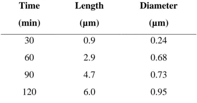
The growth rate of the NWs throughout the synthesis has been established by a kinetics study consisting in two different experiments. The first experiment consisted in the determination of the NWs growth speed all along the synthesis (Exp A1). To do so, four syntheses were done in parallel with one substrate in each solution coming from the same growth stock solution; the latter was prepared according to the modified growth procedure from section 1.2.2. The syntheses were started at the same time and stopped at different times: 30 min, 60 min, 90 min and 120 min. At the end of each synthesis, the solution was introduced into an ice bath in order to stop the homogeneous growth process, and the substrates were removed, washed with DI water and dried at room temperature. The growth solution was filtrated through filter paper (VWR grade 474 quantitative filter paper) using Büchner filtration apparatus and 5 mL of the filtrated solution were analysed by Induced Coupled Plasma Mass Spectroscopy (ICP-MS, Thermo Scientific iCAP 6500) to evaluate the quantity of zinc remaining in solution. ICP-MS is a mass spectrometer that uses a plasma to ionise the samples and detects quantitative trace of elements. The substrates were weighed after seeding, after growth, and after the homogenous ZnO was removed from the upward facing side of the substrates by cleaning it with a cotton swab moistened with 0.1 mol L-1 HCl solution. The solid recovered on the filter was dried and weighed as well.
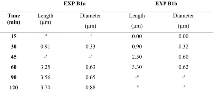
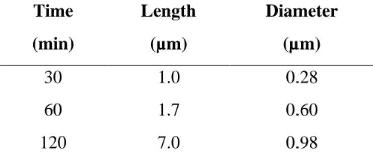
The second experiment (Exp B1a) consisted in the introduction of four slides in the same bath and their removal at 30 min, 60 min, 90 min, 120 min, while another slide was introduced in the reactive vial at the same time. To obtain additional results for intermediate times, four substrates were introduced at the same time in one chemical bath and were withdrawn at 15 min, 30 min (control sample), 45 min, 60 min (control sample) while another substrate was introduced in the reactive vial at the same time (Exp B1b). Thus, in these experiments, four glass slides were always present in the growth solution as substrates. Directly after removal, the substrates were cleaned with DI water, and dried at room temperature. The substrates were weighed after seeding, after growth, and after the homogenous ZnO was removed from the upward facing side of the substrates. Diameter and length of the NWs were measured from environmental scanning electron microscopy (ESEM-FEG XL30 Philips, Esprit 1.9 software) images. To assess the reproducibility, the two experiments (Exp A1 and B1) were repeated a second time (Exp A2 and B2).
17
Optimisation of the NW growth process from the kinetics study
The results from temperature monitoring and kinetics study (see results and discussion section) led to further optimisation of the growth procedure. In order to reach faster the growth temperature, water was preheated before adding the reactants. The water was preheated at 40 °C, 60 °C, 70 °C and 80 °C, before the reactants were added. The ZnSO4 powder (3.74 g) was directly dissolved into 19.5 mL of 4.0 mol L-1 NH4OH solution. The previous solution and 13 mL of ethanolamine were added to 97.5 mL of preheated DI water. The growth solution (130 mL) was prepared in a 160 mL polypropylene vial, giving the following final concentrations: 0.1 mol L-1 Zn2+, 0.6 mol L-1 NH
4OH and 1.7 mol L-1 ethanolamine. The solution was vigorously stirred until the pH stabilised at ~11.1 ± 0.2 (10 min). One substrate was introduced inclined from vertical to prevent particles from settling on the downward-facing seeded side of the substrate.The reaction vial was closed and placed in an oil bath (90 °C) until the temperature inside the growth solution was stable at 80 °C. At the end of the experiment, the slide was washed with DI water and dried at room temperature. The morphology of the ZnO NWs was characterised by environmental scanning electron microscopy (ESEM-FEG XL30 Philips, Esprit 1.9 software) and the length and the diameter of the NWs were measured.
Homogeneity of the temperature
Note that preliminary experiments including a magnetic stirrer in the reaction vessel, using a special sample holder, were also performed so that the growth solution was mixed during the process. Although encouraging results were obtained (i.e. better orientation of the NWs), the subject change at mid-term of the thesis made it impossible to continue the experiments and obtain a consistent dataset. Further trials should be performed to assess the impact of stirring on the NW quality.
Three different heating systems were studied. In System A, an oil bath was heated by a PID controller to 90 °C on a hot plate with the temperature probe placed into the oil (Figure 1.3a). The reaction vessel was then placed into the preheated oil. Contrarily, in System B, the temperature probe was placed directly into the reaction vessel instead of into the preheated oil bath (Figure 1.3b). System C was homemade: it consisted of building a dual-wall system made of two propylene vials where water is heated at 90 °C and circulates constantly (Figure 1.3c). A thermometer was added in the growth solution to monitor the temperature evolution.
18
Figure 1.3. Different heating systems studied. (a) A system: oil bath heated by a PID
controller to 90 °C on a hot plate with the temperature probe placed into the oil; (b) B system: oil bath heated by PID controller to 90 °C on a hot plate with the temperature probe placed directly into the reaction vessel; (c) C system: dual-wall system made of two propylene vials where water is heated at 90 °C and circulates constantly.
1.3 Results and discussion
Reproduction of growth procedure from Kokotov et al. [25]
Two different seeding procedures were studied in order to reproduce the initial procedure and adapt it to achieve the objectives of the project, which is to grow a homogeneous arrangement of flat ended hexagonal ZnO NWs, well aligned along the c-axis, at a growth rate faster than 20 nm min-1. The first procedure, via the activation of the glass substrate, consisted in immersing the glass slide into a KMnO4 solution followed by repeated rinsing. The extensive rinsing is important to prevent nucleation of ZnO in the bulk of the deposition solution from Mn-containing particles detached from the treated substrate. The activation allows facile nucleation due to adsorption of Zn species on the hydrated manganese oxide nuclei [31]. The second procedure consisted in the deposition of a solution of zinc acetate, dissolved in ethanol, onto a glass substrate using spin-coating. After calcination, ZnO nuclei are formed onto the surface which will later give rise to ZnO NWs. The two procedures were then
19 followed by the growth of NWs using the CBD method, and these NWs were characterised by ESEM.
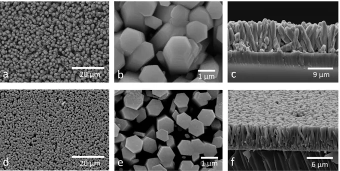
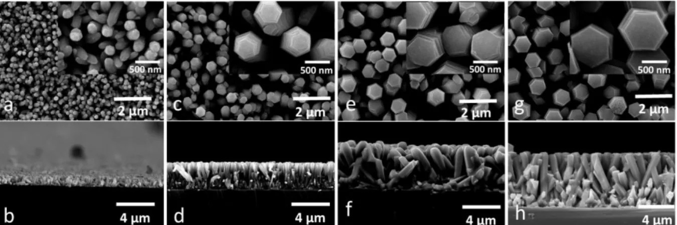
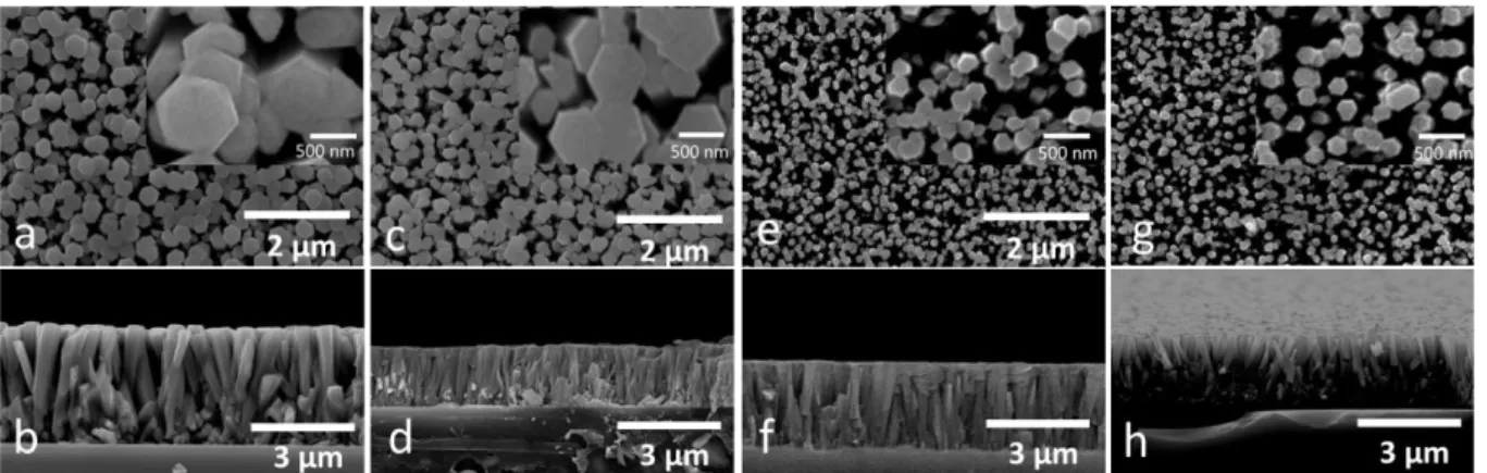
Figure 1.4. ESEM images of NWs grown with KMnO4 activation: (a) general view, (b) top view and (c) side view. NWs grown with ZnO seed layer: (d) general view, (e) top view and (f) side view.
Figure 1.4a shows NWs grown on the substrate activated with KMnO4. The deposit is not uniform in terms of NWs density all over the substrate. This procedure leads to pencil tip ended NWs whose length and diameter are respectively 11 µm and 1.2 µm (Figure 1.4b and Figure 1.4c). The procedure using a ZnO seed layer leads to a more homogeneous growth and density as shown in Figure 1.4d. The NWs show a length of 7 µm and a diameter of 0.8 µm (Figure 1.4e and Figure 1.4f). The seed layer method is thus preferred to the substrate activation as it leads to a homogeneous arrangement of flat ended hexagonal ZnO NWs, well aligned perpendicular to the substrate.
Simplification of the growth procedure from Kokotov et al. [25]
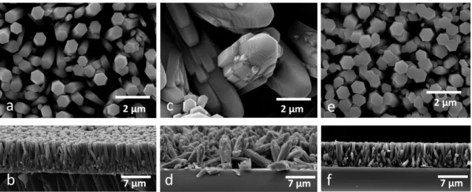
As explained in 1.3.1, using a seed layer leads to hexagonal-shaped flat ended NWs whose length and diameter are respectively 7 µm and 0.8 µm (Figure 1.5a and Figure 1.5b).
A first modification consisted in dissolving all the reactant directly in the final amount of water. The results show inhomogeneous growth of the NWs (Figure 1.5c and Figure 1.1d): NWs are oriented in any direction and do not show the expected hexagonal flat ended shape.
20 In the simplified process, zinc sulphate was first dissolved in the ammonium hydroxide solution. The direct dissolution of zinc precursor in ammonium hydroxide leads to the formation of stable species [Zn(NH3)4]z+, which will lead to the ZnO precursor, Zn(OH)2, when the growth solution is heated at 90 °C [32]. Two solutions were added to water so that the total volume of the solution was 130 mL: the first solution contained the complexed zinc and the second solution was pure ethanolamine. After combination, the mixture was stirred until pH was stabilised and heated for growth. The NWs obtained after growth with the simplified process are well formed with hexagonal flat ended shape and they are oriented perpendicular to the substrate as shown in Figure 1.5e and Figure 1.5f. They show a diameter of ~0.8 µm and a length of ~6 µm, values which are close to those of the growth procedure from Kokotov et al. [25]. The optimised procedure leads to homogeneous NWs and allows to save 50-60% of preparation time (at laboratory scale) in the preparation of the growth solution.
Figure 1.5. ESEM pictures of the NWs obtained by different procedures. (a) and (b): top and
side view of initial procedure; (c) and (d): top and side view with first modified procedure; (e) and (f): top and side view with simplified procedure.
The reproducibility of the growth process has been studied for the simplified procedure. The synthesis was fully reproduced 10 times and the morphology of the NWs obtained after growth was characterised. The two graphs in Figure 1.6a and Figure 1.6b respectively show the length and the diameter of the NWs for each distinct synthesis. The average diameter on Figure 1.5b is about 0.95 ± 0.15 µm. Even if the diameter varies from 0.75 µm to 1.12 µm, six measurements out of ten are within the standard deviation (blue frame). The average length is about 6.5 µm ± 0.5 µm and seven measurements out of ten are in the standard deviation.
21
Figure 1.6. Synthesis reproducibility in terms of (a) length and (b) diameter of the NWs.
Growth kinetics study
1.3.3.1 Study of the growth processThe visual aspect and evolution of the solution was observed during the whole growth and linked to the pH and temperature monitoring. The temperature in the growth solution stabilises at ~80 °C while the temperature of the oil bath is set at 90 °C. The temperature and pH values were stable from 50 min to the end of the synthesis. During the growth of the NWs, four steps can be observed, as shown in Figure 1.7:
(i) Between 15 and 30 min, the microscope slide is becoming opaque, which is an indication of growth on the substrate (heteronucleation process), while the solution remains clear (Figure 1.7a).
(ii) Between 30 and 60 min, besides the growth on the substrate, the solution becomes opaque, due to the formation of ZnO in solution (homogeneous nucleation – Figure 1.7b).
(iii) Between 60 and 90 min, the homogeneous ZnO precipitates at the bottom of the vial (Figure 1.7c).
(iv) Between 90 and 120 min, the solution becomes clear again and the microscope slide is coated with the NWs (opaque slide - Figure 1.7d).
22
Figure 1.7. Pictures showing the evolution of the synthesis solution after (a) 30 min, (b) 60
min, (c) 90 min and (d) 120 min.
In order to monitor the reaction medium during ZnO nanowire growth, a combined pH and temperature probe was introduced in the vial. Temperature and pH were recorded every 5 min for six different syntheses (Figure 1.8a and Figure 1.8b). The growth solution does not reach the set temperature; the growth is thus occurring at 80 °C instead of 90 °C. The pH decreases when the temperature increases. The temperature and pH values are stable from 50 min to the end of the synthesis. The graphs in Figure 1.8c and Figure 1.8d show the temperature and pH variance. The variance measures the dispersion of the values of a variable; the variance () of a set of n equally likely values can be written as:
𝑣 =
∑(𝑋𝑖−𝑋̅)²𝑛 (1)
where Xi is the ith value of variable X, 𝑋̅ is the mean of the values of this variable, and n the total number of values. In other words, the variance is defined as the average of the squared differences from the mean.
From one synthesis to another, one observes a large temperature and pH variation from the beginning of the syntheses to 45-50 min heating. This variation of temperature is probably due to the regulation of the heating plates, or the level of liquid in the pH probe. After numerous experiments, it was finally found that the maximum temperature reached in the solution depended more on the liquid level of KCl solution inside the pH probe than on other parameters (completely filled probe or ¾ filled already induced measurable differences). The KCl solution partly evaporated during the 2 h of the experiment and we did not fill the probe for each new experiment, which we should have done.
The pH decrease observed is not due to an OH- consumption: it is linked to the temperature variation, as shown in Figure 1.8e: this figure reports the evolution of pH values of a NH4OH
23 solution (prepared with pH = 11.2 at room temperature) placed in the oil bath at 90 °C while its temperature increases, then decreases when stopping the bath heating.
24
Figure 1.8. (a) Temperature monitoring and (b) pH monitoring, (c) temperature variance and
25 According to Richardson et al. [32], the mixing of ZnSO4 and NH4OH precursors leads to the formation of prevalent stable species [Zn(NH3)4]z+ at pH = 11 (25 °C). The speciation plots (extracted from Richardson et al. [32]) shown in Figure 1.9a indicate that the increased solubility is due to the formation of the zinc tetra-amine complex, Zn(NH3)42+, as the prevalent species is Zn(II) in that pH range (clear solution). When the solution is heated up, the pH range where Zn(NH3)42+ is stable shrinks and is shifted to lower pH values (pH = 7 to 9). According to Figure 1.9b, a decrease of Zn(II) solubility at pH = 11 is observed when the solution is slowly heated from room temperature to 80 °C. At pH = 11, one of the prevalent species is Zn(OH)2,which precipitates. The solution can remain near equilibrium (clear) by depositing ZnO onto the pre-existing seeds that were produced on the substrate (heteronucleation). This explains the opacity of the slide on Figure 1.7a, while the solution remains clear. The formation of a white precipitate when the solution gets close to 80 °C (30-60 min growth in our case) is due to the rapid decrease of solubility of Zn(II) species, which leads to transition reaction from [Zn(NH3)4]z+ to Zn(OH)2. This decrease in solubility leads to a supersaturation large enough to initiate the nucleation of epitaxial ZnO on the substrate and to precipitate ZnO particles in solution. This homogeneous nucleation process can limit the growth of ZnO NWs due to fast reactant consumption [32].
Figure 1.9. Speciation in an aqueous solution of dissolved Zn(II) vs. pH (a) at 25°C and (b) at
90 °C. Reprinted from reference [32].
In order to complete the study of the growth process, the distribution of the Zn (II) species was determined after different synthesis times (Exp A1). The time spans were chosen according to the visual aspect of the solution observed in Figure 1.7. Four syntheses have been done in parallel. They were started simultaneously and stopped after different times (Exp A1): 30 min, 60 min, 90 min and 120 min. At the end of each synthesis, the reaction vial was
26 introduced into an ice bath to stop the homogeneous growth process. The growth solution was filtrated using Büchner filtration.
The proportion of zinc on the glass substrate (homogeneous and NWs), in solution and on the filter was evaluated. During growth, ZnO can be formed on the seeded side of the glass substrate (NWs), on the unseeded side of the glass substrate (settling of homogeneous ZnO from the solution), and in solution; the latter phenomenon leads to the formation of a white precipitate (homogeneous ZnO) that mostly settles at the bottom of the reaction vessel and is recovered by filtration.
The substrates were weighed after seeding, after growth, and after the ZnO particles due to homogeneous nucleation were removed from the unseeded upward-facing side of the substrates. The quantity of zinc in solution was evaluated by ICP measurements. The precipitate was weighed in order to evaluate the quantity of homogeneous ZnO formed in solution during growth process.
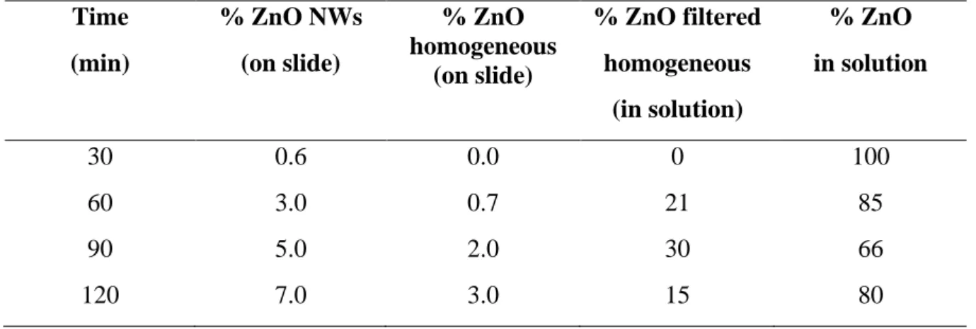
The percentage of zinc under the different forms was evaluated from the initial quantity of zinc added in the solution before growth. Table 1.1 shows the time evolution of the percentage of NWs grown on the seeded side of the slides, the percentage of homogenous ZnO settling on the upward facing side of the slides, the percentage of the filtered ZnO and the percentage remaining in solution. An increase of the percentage of the NWs and of the homogeneous ZnO deposited on the slide with time is observed (Table 1.1).
Table 1.1. Evolution of the percentage of different ZnO forms during growth. Time (min) % ZnO NWs (on slide) % ZnO homogeneous (on slide) % ZnO filtered homogeneous (in solution) % ZnO in solution 30 0.6 0.0 0 100 60 3.0 0.7 21 85 90 5.0 2.0 30 66 120 7.0 3.0 15 80
27
Figure 1.10. Evolution of ZnO during growth. ( ) Percentage of ZnO in solution, ( )
percentage of ZnO collected via Büchner filtration.
Figure 1.10 shows the (mass) percentage of ZnO in the solution and the percentage of homogeneous ZnO material collected via Büchner filtration during growth as a function of time. From the beginning of the growth to ~90 min, the percentage of ZnO in solution decreases to 60% while the percentage of precipitated homogeneous ZnO increases to 30%. At 90 min, the tendency is reversed: the fraction of solid ZnO decreases while that in solution increases. This situation is probably due to the dissolution of homogeneous ZnO material. Shaojing Bu et al. [33], showed that the growth of ZnO NWs can be described based on the chemical equilibrium of dissolution-regrowth in solution [34, 35]. The thermodynamic equilibrium for ZnO(s)-H2O system can be represented by:
ZnO(s) + (n-1)H2O ↔ Zn(OH)nz-n(aq)+ (n-2)H+ (2)
Figure 1.10 suggests that, at equilibrium, the dissolution of ZnO and growth of NWs occur simultaneously. The presence of ZnO(s) in the alkaline environment moves the equilibrium of Equation 2 to the right because of the lower concentration of Zn(OH)2z-n(aq) observed after 90 min of growth.
This first study has shown that the visual aspect of the solution during growth and the growth solution temperature evolution are linked. When the temperature is close to 80 °C, the growth of the nanowires starts. During synthesis, a competition with the ZnO formed in solution limits the growth of NWs on the substrate. Moreover, it has been shown (Figure 1.10) that the