HAL Id: hal-01015860
https://hal.archives-ouvertes.fr/hal-01015860
Submitted on 27 Jun 2014
HAL is a multi-disciplinary open access
archive for the deposit and dissemination of
sci-entific research documents, whether they are
pub-lished or not. The documents may come from
teaching and research institutions in France or
abroad, or from public or private research centers.
L’archive ouverte pluridisciplinaire HAL, est
destinée au dépôt et à la diffusion de documents
scientifiques de niveau recherche, publiés ou non,
émanant des établissements d’enseignement et de
recherche français ou étrangers, des laboratoires
publics ou privés.
Solution Space Modeling for Robotic Systems
Arun Kumar Ramaswamy, Bruno Monsuez, Adriana Tapus
To cite this version:
Arun Kumar Ramaswamy, Bruno Monsuez, Adriana Tapus. Solution Space Modeling for Robotic
Systems. Journal for Software Engineering Robotics (JOSER), 2014, 5 (1), pp.89-96. �hal-01015860�
Solution Space Modeling for Robotic Systems
Arunkumar Ramaswamy1,2 Bruno Monsuez1 Adriana Tapus1
1Department of Computer and System Engineering, ENSTA-ParisTech, 828 Blvd Marechaux, Palaiseau, France 2 VeDeCom Institute, 77 rue des Chantiers, 78000 Versailles, France
Abstract—Motivated from the experience of developing a lidar based vehicle tracking system, a model-based approach for specifying
the solution space of robotic system is proposed in this paper. Solution space modeling can expand the design space, help finding the best possible solution, identify variation points, and also permit to perform context based run-time adaptation of the system. Models based on the proposed Solution Space Modeling Language (SSML) can help in system level reasoning, making tradeoffs, documenting decisions, and comparing them based on functional and non-functional properties, and can act as an artifact for formally proving and validating the final implementation.
Index Terms—Modeling Techniques, Quality Concepts, Model-Driven Software Development, Vehicle Tracking
1
I
NTRODUCTIONArchitecting a robotic system is a science of integrating various independently operable heterogeneous systems such as perception, navigation, planner, controller, etc. Tradition-ally in robotics, the adaptation of the robotic system to the dynamic environments is embedded in the functionality of the constituent systems, for example, by designing a dynamic path planning algorithm. This practice limits the adaptation within the functional boundaries of the system components. Solution space modeling can expand this design space, help finding the best possible solution, and also permit to perform run-time adaptation of the system.
The solution space for implementing a functionality in robotics domain is large. Unlike in research laboratories, where domain experts are involved in software development, in industries there is a clear separation of roles. Domain experts design the system (e.g., using UML class diagrams) and make key decisions on algorithms that are then communicated to the software developer who develops the software code. Robotic experts can oversee various algorithmic solutions, specify abstract software component interfaces, predict high level de-pendencies, etc.; however, they may not be well versed in best
Short paper – Manuscript received November 15, 2013; revised April 30,
2014.
• This work was supported by Vedecom, a French automotive cluster
on mobility research. The research on vehicle tracking systems were conducted with the guidance from Javier Ibanez-Guzman at Renault, Research Division, France.
• Authors retain copyright to their papers and grant JOSER unlimited
rights to publish the paper electronically and in hard copy. Use of the article is permitted as long as the author(s) and the journal are properly acknowledged.
software engineering practices, cannot predict execution time of algorithms, etc. A software developer, sometimes, antici-pates and assumes several facets about the target environments while implementing and testing software components that may not be valid in the final system composition. For example, a developer may implement a particular localization algorithm that requires the sensor data to have a certain confidence level and resolution, which may not be satisfied in the target application. The underlying reason is that no formal model is used to analyze and manage the solution space available to various stakeholders. However, for various reasons described below, the robotic system designs are fallible: a) Most of the robotic system designs are purely functional, they do not explicitly capture the non-functional aspects, such as, timing properties, etc.; b) The decision on which algorithm to use is decided by the domain expert during the design phase without considering the operational profile of those functionalities and its prerequisites, run-time environment, potential interactions etc.; c) Only functional verification of individual systems is conducted and the performance of these modules cannot be guaranteed when it coexists with other systems, for example, the obstacle detection system may take more time to compute when it is executed along with other systems in the real world scenario; d) Lack of common ontologies and reluctance of roboticists to accept any standard development process.
This research paper has two main goals: first, to identify the problems faced while developing software for robotic systems in an industrial setup; secondly, to apply formal modeling techniques to partially mitigate those issues. We also discuss our vision for a model-driven ecosystem foreseen in robotics domain.
90 Journal of Software Engineering for Robotics 5(1), May 2014
Fig. 1. Test Vehicle used for vehicle tracking experiment. Lidar and GPS are mounted on top of the vehicle and embedded computers are located in the trunk of the vehicle (see picture inset).
2
M
OTIVATIONALE
XPERIMENTThe problems faced and lessons learnt during the system design, software development, and field experiments con-ducted during a research at Renault were the driving forces to propose a model-based approach. The objective of the project was to design and implement a vehicle tracking system using Velodyne HDL-64E lidar sensor. Velodyne lidar is a high definition laser scanning system that generates about a million points per second using its rotating sensor head containing 64 semiconductor lasers as shown in Figure1. The tracking system should detect vehicles in the environment and compute its state - 2D position and velocity. It was foreseen to use the system for the following scenarios: a) Ground truth generation, b) Path planning for autonomous vehicle, c) Traffic surveillance, and d) Map building applications. The project was successfully completed, however, in an ad-hoc manner that made it impractical in several other anticipated application scenarios. This section document some of those problems from our experience and classifies them into four core categories.
In our work, we employed the classical approach of per-forming data association on segmented scenes across frames followed by the probabilistic state estimation. The process flow is composed of the following four stages: a) Data acquisition: Spatio-temporal point cloud data is acquired; b) Segmentation: Points clouds are segmented to object level; c) Data association: Point cloud features are computed for segmented clusters and then associated with objects across frames; d) State estimation: Probabilistic inference methods such as Kalman Filters, PHD Filters are applied to estimate the position and velocity of the detected vehicles.
Some of the relevant problems encountered during the design and development of the tracking system are discussed below.
Large number of segmentation algorithms are available in the literature to segment point cloud data. Some of them were dependent on the type of the sensor (e.g., Lidar, Time-of-Flight Cameras), properties of data (e.g., density, resolution, colour, intensity), environment features (e.g., indoor, outdoor,
cluttered, flat or sloppy terrain, vegetative land). In addition, the intention to use the tracking system in a variety of applications, such as ground truth generation, and autonomous driving, whose requirements for timing properties, resolution and confidence levels are entirely different, makes it difficult to choose an appropriate algorithm.
The rotating head of lidar takes non-negligible amount of time to capture a frame. If the lidar is mounted on a moving vehicle, the generated 3D point cloud frames get distorted due to this motion. Since this was not properly captured in initial designs, considerable amount of time were spent on implementing software that later failed in field experiments. One such incorrect component composition was when Point Cloud Histograms (PFH) were used as feature descriptors in the data association step. PFH descriptors captures the spatial distribution of points in the point cloud. When the tracking system was used in moving vehicle without including an undistortion process on the point cloud data, the feature corre-spondences will not work. The undistortion process requires a high performance inertial localization system to compute the pose of the vehicle at the timestamp of each captured point and applies coordinate transformation to compute the exact 3D point. Such induced requirements and constraints must be captured to make the system more adaptable, for run-time dynamic wiring of software components, and for deriving a product from product line systems.
Context information was unavailable during design time as well as during field experiments. Certain algorithms can be integrated to the system only by using such information, for example, an object classifier needs the road information to help in classifying between vehicles or buildings on the road side, between pedestrians and parking poles, etc. Several algorithms (ground classification, for instance) require parameter selection based on the context, such as terrain type - sloppy or flat, road width, etc.
The previously discussed problems can be broadly classified into three categories:
1) Uncertain problem space: Ambiguity in requirements due to the desire to reuse the system across various applications.
2) Large solution space: Availability of multiple algorithms for implementing a functionality.
3) Lack of design time context information: The developer cannot anticipate all the use cases and his/her assump-tions are not properly documented.
4) Level of Abstraction: Code-centric designs cannot pro-vide the right level of abstraction that promote portabil-ity and reusablportabil-ity.
This paper proposes a modeling language to formally model the solution space and to specify the quality attributes during design time. The approach is to capture multiple solutions in the model that permits formal analysis, reasoning, and decision making on selecting best possible solution depending on the functional and non-functional properties. The solution model
Fig. 2. Relationship between the proposed models
will also help in - system level reasoning, making tradeoffs, documenting decisions and comparing them, and for formally proving and validating the final implementation.
The rest of the paper is organized as follows: Section
3 discusses various aspects of modeling solution space and provides a meta-metamodel. The concept of functional and non-functional properties and their corresponding metamodels are described in section 3.1 and section 3.2, respectively. Section 4 applies the proposed modeling language to model the solution space for the previously discussed vehicle tracking problem. Section 5 provides the related works and discuss the model driven software development in robotics. Section 6
concludes the paper with future directions.
3
S
OLUTIONS
PACEM
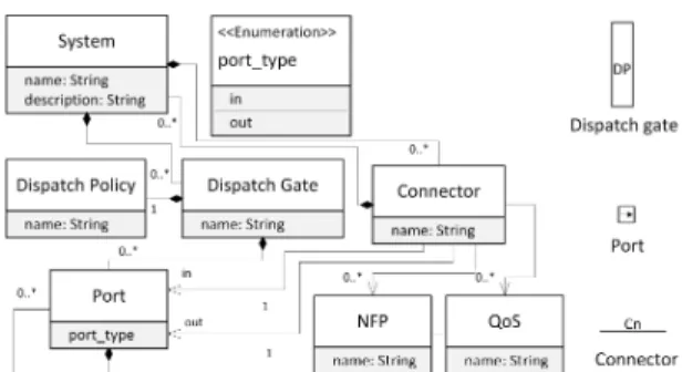
ODELBy critical analysis of the problems described in section2, the desirable features for a solution space model are deduced: a) It should be a graphical model that can be visually inspected, as well as machine readable; b) It must be a hierarchical model that provides views at different granularity levels; c) Non-Functional Properties (NFP) and Quality of Service (QoS) must be explicitly stated; d) It must capture the uncertainties in problem space and must act as a reference model for developing concrete software models in the operational space. Equally important to the desirable features, the model should not include any implementation specific details, such as com-munication patterns and programming language dependencies. In this paper, a Solution Space Modeling Language (SSML) is proposed. SSML is specified at two abstract levels as shown in Figure 2. Solution space meta-metamodel is at the highest level and functional and non-functional metamodels at the lower level in the MDE hierarchy. Figure 3 shows the Ecore meta-metamodel diagram and the graphical representation of the primitive elements. In natural language, the syntax can be explained as follows: the solution space consists of Dispatch Gates, Ports, Connectors as the primitive elements. A Dispatch gate consists of number of ports and is associated with a Dispatch Policy. The ports can be ‘in’ or ‘out’ indicated by the port_type. A connector is associated with two ports of which one should be an ‘in’ port and the other an ‘out’ port. A connector can have NFP and QoS associated with it.
The semantics of the proposed model is as follows: the dispatch gates represent basic operations for composing dif-ferent functional computational processes, such as selecting an appropriate data source for a computation, synchronization
Fig. 3. Metamodel (left) and its graphical representation (right) of SSML. Dispatch Gate, Port, and Connector rep-resents the functional aspect and NFP and QoS Profile represents the non-functional aspect.
point, buffering, etc. The dispatch policy associated with it defines the operation of the gate. The data enters or leaves the gates through ports. Ports can be of type ‘in’ or ‘out’ depending on whether the data enters or leaves the gate. A connector connects two semantically compatible ‘in’ and ‘out’ ports. A Connector represents a functional computation and its quality aspects are represented by NFP and QoS.
3.1 Functional Model
A functional model satisfies the behavioral requirements of the system. A behavioral or functional requirements are those requirements that specify the inputs (stimuli) to the system, the outputs (response) from the system, and the behavioral relationships between them [1]. The functional model in the solution space should not be interpreted as a data flow diagram, but as a relationship diagram between functional concepts. 3.1.1 Functional Metamodel
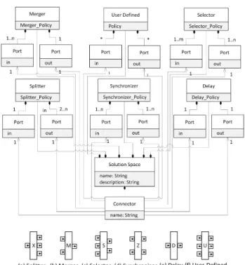
A functional metamodel is depicted in Figure4that conforms to the solution space meta-metamodel. This metamodel im-poses soft constraints on the dispatch policies of the gates and the number of ports [2]. Soft constraints means that the dispatch policies are not concretely defined but only conceptual restrictions are only imposed in the metamodel. The intention is to facilitate the designer to apply application specific policies, at the same time, the gates can be used for automated reasoning of the solution space.
a) Splitter gate consists of 1 input port and n output ports. It creates n splits/copies of the input data and transfers to its output ports.
b) Merger gateconsists of n input ports and 1 output port. It merges the data from n input ports to the output port. c) Selector gateconsists of m input ports and n output ports. It selects n out of m input data.
d) Synchronizer gateconsists of an equal number of input and output ports. It acts as a synchronization point between the different data streams.
92 Journal of Software Engineering for Robotics 5(1), May 2014
Fig. 4. Metamodel for functional modeling (top) and graphical representation of dispatch gates (bottom).
e) Delay gate consists of one input and output port. It passes the data in the input port after a time delay and can also act as a data buffer.
f) User-defined gate does not have any constraints on the number of ports and dispatch policy.
3.2 Non-Functional Model
A non-functional model satisfies Non-Functional Require-ments (NFR) and quality claims of the system. There is no general agreement in the community about the concepts of NFP and QoS. In [3], the authors define Non-Functional Prop-erties (NFP) as one that specifies system propProp-erties, such as environmental and implementation constraints, performance, platform dependencies, maintainability, extensibility, and reli-ability; in short, a requirement that specifies constraints on a functional requirement. QoS is the aptitude of a service for providing a quality level to the different demands of the clients [4]. NFR are not implemented in the same way as functional ones. NFPs are seen as by-products when a functionality is implemented. In software engineering terms, usability, integrity, efficiency, correctness, reliability, maintain-ability, etc. constitute NFPs [5]. However, how these properties are defined, are domain-specific. For example, throughput and bandwidth determine QoS for a network; personality, empathy, engagement, and adaptation for social robots [6]; resource utilization, run-time adaptation for service robots [7].
In order to set a general consensus, based on empirical observations, the following assumptions are made: A NFP
Fig. 5. UML Metamodel diagram for specifying Non-Functional properties.
are determined by a set of non-functional attributes (e.g., performance of a object classifier can be estimated by the time required for classification; and its efficiency by the rate of misclassification, etc.). QoS is a high level property for comparing a functionality in different contexts (e.g., QoS of a specific object classification algorithm is better in indoors as compared to outdoor environments). Policies associated with NFP and QoS determine how these properties are estimated from its constituent attributes. Policies are functions that act on a set of attributes, and define how these properties are estimated. Policies can be defined using logic systems, such as a first order logic, predicate logic, etc [8]. In a nutshell, NFP_Policy(NFP attributes) defines NFP, QoS_Policy(NFPs, Context) defines QoS of a func-tionality. Although, there is no strict rule to identify whether a property is NFP or QoS. In this paper, we use a rule of thumb that a functionality (or system) can have multiple NFPs (e.g., performance, efficiency), but can have only a single QoS property (e.g., QoS_Policy(performance, efficiency, context) defines QoS).
3.2.1 Non-Functional Metamodel
Based on the assumptions made in section3.2, we propose a metamodel for specifying the NFP as shown in Figure5. NFP and QoS are the root entities in this metamodel. NFP has at least one NFP Policy and a set of NFP Attributes. Similarly, QoS has at least one QoS Policy and a set of NFPs as its attributes. NFP attributes can be Quantitative or Qualitative. Quantitative attributes can be directly measured or can be estimated. Quantitative attributes have metric units associated with it, for example: seconds for responsiveness, bits per second for throughput, etc. The quantitative attributes can be static, dynamic, or derived. Static attributes will not change during the course of system operation, for example, pixel density of a camera. Dynamic attributes can change during system operation, for example, frames per second of a camera. Derived attributes can be static or dynamic depends on the constituent attributes when they are hierarchically composed. Qualitative attributes refer to discrete characteristics that may
Fig. 6. Solution space model for tracking system. High level model is shown (top), zero delay gates (G1-5) are inserted to separate the computations. Connector C1 representing data preprocessing is modeled (bottom)
not be measured directly but provide a high level abstraction that are meaningful in a domain, for example, reliability of a network channel. Sometimes a qualitative attribute needs some quantitative measures also, for instance, round robin scheduler with a refresh rate of 100ms.
4
S
OLUTIONS
PACEM
ODEL FORL
IDARB
ASEDV
EHICLET
RACKINGS
YSTEMThis section models the solution space of a lidar based vehicle tracking problem using the proposed SSML. Figure 6 shows the high level model of a classical approach in tracking described in section 2. Four connectors, C1, C2, C3, C4, represent data preprocessing, segmentation, data association, and state estimation process and the zero delay gates are inserted to differentiate between these processes. This model consists of single sequence of processes that do not have multiple solution paths at this hierarchical level. In this paper, a solution is referred as an execution path or simply a path in the solution space model. In textual form, it is represented as a sequence of labels indicating gates and nodes in that solution. The path represented by adjacent parenthesis, for example (path 1)(path 2), indicates a mandatory parallel execution path. The lidar data preprocessing solution model captures two solu-tions: G11-C11-G12-C13-G15-C18 and G11-(C11-G12-C14-G13-C16)(C12-G13-C15)-G14-C17-G15-C18. The two solu-tions do the same functionality: converting raw sensor data into point cloud frame. The difference between the two paths is the quality aspect that changes with context. In this case, context represents the motion of the vehicle and the difference in quality is due to time latency of lidar, as explained in section 2. The NFPs that are considered for this process are performance and resource cost. The NFP attributes that
model performance are response time, resolution, and average distortion. An example snippet from the NFP model for data preprocessing represented by C11 is shown in Listing1.
CONTEXT: vehicle
NFP: vehicle_motion
NFP_ATTRIBUTES: velx:base_velocity_x:msrd:dynamic:mps, vely:base_velocity_y:msrd: dynamic:mps, velz:base_velocity_z:msrd:dynamic:mps, rr:roll_rate:msrd:dynamic :degpsec, pr:pitch_rate:msrd:dynamic:degpsec, yr:yaw_rate:msrd:dynamic: degpsec; NFP_POLICY: vehicle_motion_policy(); *********************************************************************************** NFP: C11.response_time; NFP_ATTRIBUTES: fps:frame_per_second:msrd:static:int,tp:transmission_speed:msrd: static:msec;wcet:worst_case_execution_time:est:static:msec; NFP_POLICY: response_time_lidar_policy();
---IMPORT CONTEXTvehicle;
NFP: C11.resolution; NFP_ATTRIBUTES: ar:angular_resolution:est:static:deg,rps:rotations_per_second:msrd: static:Hz,tlppr:total_laser_points_revolution:msrd:static:int,pplpr: points_per_laser_per_revolution:msrd:static:int; NFP_POLICY: resolution_lidar_policy(); ---IMPORT NFPC11.response_time,C11.resolution,C11.average_distortion NFP: C11.performance; NFP_ATTRIBUTES: rtl:response_time,rl:resolution_lidar; NFP_POLICY: c11_performance_policy();
---IMPORT CONTEXTvehicle,environment;
IMPORT NFPC11.performance, C11.resource_cost;
QOS: C11.QoS
NFP: C11.performance,C11.resource_cost;
QOS_POLICY: C11_QoS_Policy();
Listing 1. Relevant snippets of the Non-Functional Model of vehicle, environment, and lidar data preprocessing process.
Another significant advantage of modeling functional and non-functional aspects separately is that certain invalid com-positions of systems can be found. For example, referring to the problem described in section 2 regarding PFH feature correspondence failure, such anomalies in system composition can be captured without explicitly indicating that PFH feature ‘requires’ undistortion process. Resolution property of lidar data preprocessing process shown in Listing 1 using vehicle context to determine the resolution of the point cloud data. Hence, if PFH feature that requires a better resolution is composed without undistortion process, the QoS of the system will be lower since the resolution constraint does not satisfy point cloud resolution level.
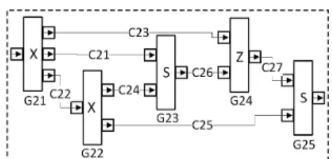
The solution space for segmentation process represented by connector C2 in Figure6is modeled in Figure7. The objective is to cluster a point cloud frame into smaller clusters in such a way that each cluster represents individual objects. There are multiple data processing steps and algorithms to achieve the goal. In general, a point cloud data can be segmented into clusters using two methods: 1) By directly processing the 3D data and clustering using some criteria such as Euclidean distance or 2) By mapping the point cloud to a 2D image and performing segmentation in 2D space using image processing techniques and then projecting back to the 3D space to compute the final point cloud clusters. Each algorithmic step indicated in Figure7 is briefly explained as follows:
Ground Classifier: The algorithm can classify ground and non-ground points from a point cloud frame. By rejecting the ground points, this algorithm can significantly reduce the number of points for further processing.
2D Projection Method:This method uses (x,y) coordinates of the point cloud and converts it to a two-dimensional binary
94 Journal of Software Engineering for Robotics 5(1), May 2014
Fig. 7. Connector C2 representing segmentation shown in Figure6is modeled in the figure
TABLE 1
Solution comparison for segmentation w.r.t application: Ground truth generation and Autonomous Driving
No.Execution Path Variation Points 1 G21-(C21-G23-C26)(C23)-G24-C27-G25 (C21), 2 G21-(C22-G22-C24-G23-C26)(C23)- (C22-G22-C24) G24-C27-G25 (C24-G24-C27), 3 G21-C22-G22-C25-G25 (C25) Subpath No. Variation
Performance Ground Truth Generation
Autonomous Driving AET Res. Stage 1 Stage 2 Stage 1 Stage 2
1 (C21) 48ms Med Fail Pass Pass
2 (C22-G22-C24) 107ms High Pass Pass Fail
3 (C24-G24-C27) 31ms Med Pass Fail Pass Fail
4 (C25) 120ms Low Fail Fail
image. This is best suited for point clouds consisting of non-ground points and hence, it receives data from a non-ground classifier.
Euclidean Clustering: This algorithm uses Euclidean distance to cluster the point clouds. It can be applied on non-ground point cloud data to generate the final point cloud clusters. 2.5D Projection: This algorithm can convert a point cloud to a 2D grayscale image. Ground points are automatically rejected and there is no requirement for explicitly classifying the ground and non-ground points.
Image Segmentation:Using image processing techniques, con-nected regions are found in the image and a bounding box is computed for each region.
2D to 3D Box Mapping This uses a list of 2D boxes and the correspondence point clouds and generates 3D point cloud clusters. Some intermediate results are shown in Figure 8.
The NFP of segmentation process are modeled in a similar way as previously described in this section. In this example, two contexts are considered; one for a ground truth generation application and another for autonomous driving application. The intention is to reason, analyze, and extract appropriate solutions from the solution space that satisfy the context re-quirements. If two or more solutions satisfy the requirements, it will be considered as variation point that can be resolved in the design or implementation phase, or dynamically selected during run-time. For simplicity, only the performance property is considered here. The performance is modeled with two NFP
Fig. 8. Vehicle Tracking Results: Segmented point clouds (left), detected vehicles (middle), tracked vehicles (right)
attributes - Average Execution Time (AET) and Resolution. AET is computed as the average time taken to execute the computation and it is estimated in the test platform, since an accurate timing information is not required at this stage. Also it is reasonable to compare the AET of different computations on the same platform for primary investigations. The resolution is divided into three levels depending on the grid size of the map: High, Medium, and Low, to facilitate the demonstration. The appropriate solution in different contexts is extracted in a staged process as described below:
1) Find the multiple solutions available in the solution space model.
2) Find the variation sub-paths among the multiple solution paths.
3) List the sub-paths from the variations found in step 2. 4) For a given context, find whether the homogeneous
sub-paths satisfy the quality policy (NFP or QoS Policy) of that subpath. A homogeneous paths is a set of sub-paths that perform exactly the same functionality. 5) Consider all the sub-paths satisfied in step 4 and check
for any contradictory results, for example, if the solution passed in one homogeneous check and failed in another. 6) If there were any contradictory results, repeat the quality check for the solution at the higher level in the hierarchy. The solution resolution steps of segmentation model are captured in Table1. There are three execution paths as listed in the table. Two variation points are then found - one variation sub-path between execution path 1 and 2 and the second between 2 and 3. It is to be noted that individual paths that end with a synchronizer gate cannot be considered as separate execution path since all the paths are mandatory for synchronization. The next step is to list out the sub-paths in the variation points. The four sub-paths are indicated in the second half of the table. The sub-path 1 and 2, and 3 and 4 are homogeneous pairs since they represent the same functionality. The policy used were (Resolution==High) for ground truth application and (Resolution==High) AND (AET<50ms) for autonomous driving application. In stage 1, two solutions satisfy the policy and in the next stage, one solution is extracted by considering the policy in that level.
Fig. 9. Overview of Models Ecosystem in Robotics
5
M
ODEL-D
RIVENS
OFTWARED
EVELOP-MENT IN
R
OBOTICS ANDR
ELATED WORKSBy learning from the shortcomings of code-based approaches, the software engineering community in robotics is gradu-ally moving towards Model-Driven Software Development (MDSD) approach [9]. This section positions our approach and discusses related works. A typical MDSD approach starts by designing abstract models that conforms to meta-level models or Domain-Specific Languages (DSL). The models undergo a series of Model to Model transformations (M2M) to reduce the abstraction levels by gradually including platform-specific details and finally, by applying Model to Text transformation (M2T) to generate executable code.
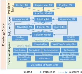
The software development process in robotics can be con-ceptually divided into three spaces: problem space, solution space, and operational space. Each space can be further classified into knowledge level and application level. The complete ecosystem is illustrated in Figure9and the proposed SSML model is highlighted as a red box. In problem space, the problem, requirements, and contexts are modeled using appropriate Modeling Languages (ML). The solution model captures the large solution space that satisfies the problem model. The SSML proposed in this paper provide abstract syn-tax with limited semantic content for modeling the solution. The syntactic and semantic enrichment is done by specific sub-domain modeling languages such as perception, navigation, control, kinematics, planner, etc. More strict validation rules and domain-specific constraints can be added once the sub-domain semantics are added. The DSLs proposed by authors of [10], [11], and [12] for kinematics, rigid body geometric relations, and perception are promising works in this direction. Operational space comprises of more concrete models that can be modeled using state machines, UML profiles such as Marte, SysML, etc. which are popular in software engineering
community. In addition, there are encouraging works from the robotics community, for example, the Smartsoft framework is based on a model-driven toolchain that provides the model transformations and code generation steps [13]. The European project on Best Practices in Robotics (BRICS) provides guide-lines and a framework to develop robotic components [14]. They are based on the separation of concerns between the development aspects of Computation, Communication, Coor-dination, Configuration, and Composition. The final executable codes are then generated using a semi-automated process by including external libraries and ‘hand-coded’ software code and by a mapping process that transforms model properties to code-based frameworks.
Modeling solution space using SSML can be seen as a complementary approach to many existing methods in the robotics. Software product line approach is popular in software engineering community to enhance product quality and reduce developmental cost by promoting constructive reusability [15]. Recently, the authors of [16] have adapted this approach in robotic domain by providing feature resolution and transfor-mation steps. However, one should have already identified well defined boundaries for variation points and a reference archi-tecture for adapting this approach. In addition, many DSLs are proposed in robotics domain for deployment, simulation [17], component creation [18], etc. All these languages reside in the operational space, our proposed SSML can complement and facilitate a smooth transition from problem space to operational space.
Our approach of providing common syntax with semantic content, whose semantic enrichment is provided specialized sub-domain specific language is related to that of ACME [19]. ACME is an interchange language for software architecture that provides structural core that represents commonalities between various Architectural Description Languages (ADL) [20]. ACME uses annotations to add semantic information by sub-languages. The Architecture Analysis and Design Language (AADL) is a modeling language standardized by Society of Automotive Engineers (SAE) to specify and ana-lyze software architectures for complex real-time embedded systems. AADL supports variability modeling in large-scale product lines in automotive domain [21].
6
C
ONCLUSIONThe research work focuses on the problems faced while de-veloping a lidar based vehicle tracking system. The problems were classified into four categories: uncertain problem space, large solution space, lack of design-time context information, and abstraction issue. In this paper, Solution Space Modeling Language is proposed to address the multiple solution problem and to formally specify NFP during system design. Solution model helps in early analysis of quality attributes, to identity variations and acts as a bridge between problem and imple-mentation space. The relevancy of the model is demonstrated by modeling the solution space of vehicle tracking problem.
96 Journal of Software Engineering for Robotics 5(1), May 2014
NFP and QoS Policies facilitated the quality flow across functionalities at different granularity levels.
More research is required on formal methods for specifying composable policies of Gates, NFP, and QoS in the proposed SSML language. Once the solution space of a problem is modeled, an appropriate solution or a set of solutions are selected depending on the application context and quality re-quirements. A transformation model will facilitate this process of mapping to the operational space models, for example, discrete timing properties of gates can be employed for process allocation, selecting scheduling policies, etc. Future works include providing tooling support based on Eclipse IDE for graphical and textual editing of SSML models and using Eclipse plug-in feature for semantic enrichment of the model.
R
EFERENCES[1] A. M. Davis, Software requirements: objects, functions, and states. Prentice-Hall, Inc., 1993. 3.1
[2] A. Ramaswamy, B. Monsuez, and A. Tapus, “Formal models for cogni-tive systems,” in 16th International Conference on Advanced Robotics
(ICAR). IEEE, 2013, pp. 1–8. 3.1.1
[3] I. Jacobson, G. Booch, and J. E. Rumbaugh, The unified software
development process-the complete guide to the unified process from the original designers. Addison-Wesley, 1999.3.2
[4] MARTE, UML Profile for MARTE: Modeling and Analysis of
Real-Time Embedded Systems, version 1.1 ed., Object Management Group, June 2011.3.2
[5] L. Chung and J. C. S. do Prado Leite, “On non-functional requirements in software engineering,” in Conceptual modeling: Foundations and
applications. Springer, 2009, pp. 363–379.3.2
[6] A. Tapus, M. J. Mataric, and B. Scassellati, “Socially assistive robotics,”
IEEE Robotics and Automation Magazine, vol. 14, no. 1, p. 35, 2007.
3.2
[7] J. F. Ingl´es-Romero, A. Lotz, C. V. Chicote, and C. Schlegel, “Dealing with run-time variability in service robotics: Towards a dsl for non-functional properties,” arXiv preprint arXiv:1303.4296, 2013. 3.2
[8] N. S. Rosa, P. R. Cunha, and G. R. Justo, “Process(nfl): a language for describing non-functional properties,” in System Sciences, 2002. HICSS.
Proceedings of the 35th Annual Hawaii International Conference on System Sciences. IEEE, 2002, pp. 3676–3685. 3.2
[9] C. Schlegel, T. Haßler, A. Lotz, and A. Steck, “Robotic software systems: From code-driven to model-driven designs,” in International
Conference on Advanced Robotics (ICAR). IEEE, 2009, pp. 1–8.5
[10] M. Frigerio, J. Buchli, and D. G. Caldwell, “A domain specific language for kinematic models and fast implementations of robot dynamics algorithms,” arXiv preprint arXiv:1301.7190, 2013.5
[11] T. De Laet, W. Schaekers, J. de Greef, and H. Bruyninckx, “Domain specific language for geometric relations between rigid bodies targeted to robotic applications,” arXiv preprint arXiv:1304.1346, 2013.5
[12] N. Hochgeschwender, S. Schneider, H. Voos, and G. K. K. I., “Towards a robot perception specification language,” in Proceedings of
DSLRob-2013, 2013.5
[13] C. Schlegel and R. Worz, “The software framework smartsoft for imple-menting sensorimotor systems,” in IEEE/RSJ International Conference
on Intelligent Robots and Systems (IROS), vol. 3. IEEE, 1999, pp. 1610–1616.5
[14] H. Bruyninckx, N. Hochgeschwender, L. Gherardi, M. Klotzb¨ucher, G. Kraetzschmare, D. Brugali, A. Shakhimardanov, J. Paulus, M. Reck-haus, H. Garcia, D. Faconti, and P. Soetens, “The BRICS Component Model: A Model-Based Development Paradigm for Complex Robotics Software Systems,” in 28th international Symposium On Applied
Com-puting (SAC 2012). Coimbra, Portugal: ACM, March 21 2013, pp. 1758–1764.5
[15] P. HEYMANS, J.-C. TRIGAUX, and F. E. Objectif, “Software product lines: State of the art,” 2003. 5
[16] L. Gherardi, “Variability modeling and resolution in component-based robotics systems,” Ph.D. dissertation, University of Bergamo, Italy, 2013.
5
[17] S. Dhouib, S. Kchir, S. Stinckwich, T. Ziadi, and M. Ziane, “Robotml, a domain-specific language to design, simulate and deploy robotic ap-plications,” in Simulation, Modeling, and Programming for Autonomous
Robots. Springer, 2012, pp. 149–160.5
[18] L. Manso, P. Bachiller, P. Bustos, P. N´u˜nez, R. Cintas, and L. Calderita, “Robocomp: a tool-based robotics framework,” in Simulation, Modeling,
and Programming for Autonomous Robots. Springer, 2010, pp. 251– 262. 5
[19] D. Garlan, R. Monroe, and D. Wile, “ACME: An Architecture Descrip-tion Interchange Language,” in CASCON First Decade High Impact
Papers. IBM Corp., 2010, pp. 159–173.5
[20] P. C. Clements, “A survey of architecture description languages,” in
Proceedings of the 8th international workshop on software specification and design. IEEE Computer Society, 1996, p. 16.5
[21] P. H. Feiler, D. P. Gluch, and J. J. Hudak, “The architecture analysis & design language (aadl): An introduction,” DTIC Document, Tech. Rep., 2006. 5
Arunkumar Ramaswamy is a Ph. D. student
at ENSTA-ParisTech in France. His research interests include mobile robots, robot architec-tures, computer vision, human-robot interaction and software engineering. Currently, he is inves-tigating how model-driven approaches can be applied in software development for robotic sys-tems. Arunkumar received his dual Master de-gree in Robotics from Ecole Centrale de Nantes in France (2012) and Warsaw University of Tech-nology in Poland (2011). He received his B. Tech degree in Electronics and Communication Engineering from Amrita University in India (2008).
Bruno Monsuez graduated in 1989 from Ecole
Polytechnique , received a Ph. D. in Computer Science from the Ecole Polytechnique in 1994. He is now Director of the Computer and System Engineering Department at ENSTA ParisTech. His current research interests are focused on developing and enhancing hierarchical composi-tional models that can be used to model complex cyber-physical systems, mostly for safety critical application as well as on designing system ar-chitectures based on design patterns that can be proved correct by composition. He also conduct researches on novel formal verification techniques that allow a co-jointly verification the functional and non-functional properties of all the components of a system. He served on PCs and as PC chair for numerous international workshops and conferences. He is the steering committee chair of Int. Workshop on Verification and Evaluation of Computer and Communica-tion Systems (VECoS).
Adriana Tapus is a Full Professor at
ENSTA-ParisTech since May 2009. She received her Ph. D. in Computer Science from Swiss Fed-eral Institute of Technology, Lausanne (EPFL) in 2005 and her degree of Engineer in Com-puter Science and Engineering from Politehnica” University of Bucharest, Romania in 2001. She worked as an Associate Researcher at the Uni-versity of Southern California (USC), where she pioneered the development of socially assistive robotics, also participating to activity in machine learning, human sensing, and human-robot interaction. Her main inter-est is on long-term learning (i.e. in particular in interaction with humans), on-line robot behavior adaptation to external environmental factors, and modeling non-functional properties for human-machine systems. She received the Romanian Academy Award for her contributions in assistive robotics in 2010.