VERIFICATION OF THE PERFORMANCE PROPERTIES OF EMBEDDED STREAMING APPLICATIONS VIA CONSTRAINT-BASED SCHEDULING
OLFAT ELMAHI
D´EPARTEMENT DE G´ENIE INFORMATIQUE ET G´ENIE LOGICIEL ´
ECOLE POLYTECHNIQUE DE MONTR´EAL
TH`ESE PR´ESENT´EE EN VUE DE L’OBTENTION DU DIPL ˆOME DE PHILOSOPHIÆ DOCTOR
(G ´ENIE INFORMATIQUE) JUIN 2016
c
´
ECOLE POLYTECHNIQUE DE MONTR´EAL
Cette th`ese intitul´ee :
VERIFICATION OF THE PERFORMANCE PROPERTIES OF EMBEDDED STREAMING APPLICATIONS VIA CONSTRAINT-BASED SCHEDULING
pr´esent´ee par : ELMAHI Olfat
en vue de l’obtention du diplˆome de : Philosophiæ Doctor a ´et´e dˆument accept´ee par le jury d’examen constitu´e de :
Mme BOUCHENEB Hanifa , Doctorat, pr´esidente
M. PESANT Gilles, Ph. D., membre et directeur de recherche
Mme NICOLESCU Gabriela, Doctorat, membre et codirectrice de recherche M. BELTRAME Giovanni, Ph. D., membre et codirecteur de recherche M. BOIS Guy, Ph. D., membre
DEDICATION
To my daughters for bringing the hope and happiness to my life, my husband for his everlasting love, support, and encouragements, my parents and sisters for their unquestioning faith in me. . . .
ACKNOWLEDGEMENT
Firstly, I would like to thank my supervisors, Gilles Pesant, Gabriela Nicolescu, and Giovanni Beltrame, for their time, support, and wisdom. they have been not only provi-ding me with invaluable ideas through out the work but also being available to help me every time I have challenges and difficulties.
I would like to give special thanks to Tamer Abd El-Dayem, my husband, who has been a great help not only during my PhD. study but also during the years of my life abroad.
I also like to thank my mother Olfat Abou-Halawa and my father Ibrahim El-Mahi for paying all the sacrifices to make me reach where I am today.
I extend my regards to all of my sisters Merit E-Mahi, HebaTallah El-Mahi and, Me-naTallah El-Mahi, who have been encouraging me, supporting me, and more importantly praying for me. I deeply thank my aunt Mervat Abou-Halawa for her non-stop encoura-gement and support.
But above all, I thank Allah for providing me with such helpful professors, caring family, and supportive friends. Thank You God !
R´ESUM´E
Les capacit´es et, en cons´equence, la complexit´e de la conception de syst`emes embarqu´es ont ´
enorm´ement augment´e ces derni`eres ann´ees, surfant sur la vague de la loi de Moore. Au contraire, le temps de mise en march´e a diminu´e, ce qui oblige les concepteurs `a faire face `
a certains d´efis, ce qui les poussent `a adopter de nouvelles m´ethodes de conception pour accroˆıtre leur productivit´e. En r´eponse `a ces nouvelles pressions, les syst`emes modernes ont ´
evolu´e vers des technologies multiprocesseurs sur puce. De nouvelles architectures sont ap-parues dans le multitraitement sur puce afin d’utiliser les ´enormes progr`es des technologies de fabrication. Les syst`emes multiprocesseurs sur puce (MPSoCs) ont ´et´e adopt´es comme plates-formes appropri´ees pour l’ex´ecution d’applications embarqu´ees complexes.
Pour r´eduire le coˆut de la plate-forme mat´erielle, les applications partagent des ressources, ce qui peut entraˆıner des interf´erences dans le temps entre les applications dues `a des conflits dans la demande des ressources. Les caract´eristiques d’un SoC typique imposent de grands d´efis sur la v´erification SoC `a deux ´egards. Tout d’abord, la grande ´echelle de l’int´egration du mat´eriel m`ene `a des interactions mat´eriel-mat´eriel sophistiqu´ees. Puisqu’un SoC a de multiples composants, les interactions entre ceux-ci pourraient donner lieu `a des propri´et´es ´
emergentes qui ne sont pas pr´esentes dans un seul composant. En second lieu, l’introduction de logiciels dans le comportement du mat´eriel m`ene `a des interactions mat´eriel-logiciel sophis-tiqu´e. Puisqu’un SoC a au moins un processeur, le logiciel constitue une nouvelle dimension des comportements du SoC et donc apporte une nouvelle dimension `a la v´erification. Cela rend la v´erification d’une tˆache difficile, en particulier pour les applications de communica-tion et de multim´edia. Cela est dˆu `a des contraintes non-fonctionnelles des modules mat´eriel et logiciel, tels que la vitesse du processeur, la taille de la m´emoire tampon, le budget de l’´energie, la politique de planification, et la combinaison de multiples applications.
Cette th`ese pr´econise la programmation par contraintes (CP) comme un outil puissant pour la v´erification des mesures de performance de MPSoCs. Dans ce travail, nous avons consi-d´er´e des applications de diffusion sur l’architecture cible d’un syst`eme-sur-puce (MPSoC) multi-processeur comme un probl`eme d’ordonnancement `a base de contraintes. Nous l’avons test´e s´epar´ement et en interaction avec d’autres types d’applications. L’id´ee est de cr´eer un sc´enario au niveau du syst`eme qui prend en compte le flux de travail au niveau du syst`eme par rapport aux ressources du syst`eme et des exigences de performance, `a savoir les d´elais
de la tˆache, le temps de r´eponse, le CPU et l’utilisation de la m´emoire, ainsi que la taille de la m´emoire tampon. Plus pr´ecis´ement, nous examinons si le comportement des diff´erentes interactions entre les composants du syst`eme d’ex´ecution des tˆaches diff´erentes peut ˆetre effi-cacement exprim´e comme un probl`eme d’ordonnancement `a base de contraintes sur l’espace des entr´ees possibles du syst`eme, afin de d´eterminer si nous pouvons traiter des cas similaires d’´echec en utilisant ce mod`ele. R´esoudre ce probl`eme consiste `a trouver une meilleure fa¸con d’inspecter le syst`eme en cours de v´erification dans une phase de conception qui arrive tr`es tˆot et dans un d´elai beaucoup plus raisonnable.
Notre approche propos´ee a ´et´e test´ee avec diverses applications, diff´erents flux d’entr´ee et des architectures diff´erentes. Nous avons construit notre mod`ele en prenant en consid´eration les architectures existantes sur le march´e, des applications choisies qui sont en courante et compar´e les r´esultats de notre mod`ele avec les r´esultats provenant de l’ex´ecution des applica-tions r´eelles sur le syst`eme. Les r´esultats montrent que la m´ethode permet de d´eterminer les conditions de d´efaillance du syst`eme dans une fraction du temps n´ecessaire `a la v´erification par simulation. Il donne `a l’ing´enieur d’essai la possibilit´e d’explorer l’espace de conception et d’en d´eduire la meilleure politique. Il contribue ´egalement `a choisir une architecture ap-propri´ee pour des applications en cours d’ex´ecution.
ABSTRACT
The abilities and, accordingly, the design complexity of embedded systems have expanded enormously in recent years, riding the wave of Moore’s law. On the contrary, time to market has shrunk, forcing challenges onto designers who in turn, seek to adopt new design methods to increase their productivity. As a response to these new pressures, modern-day systems have moved towards on-chip multiprocessing technologies. New architectures have emerged in on-chip multiprocessing in order to utilize the tremendous advances of fabrication tech-nology. Multiprocessor Systems on a Chip (MPSoCs) were adopted as suitable platforms for executing complex embedded applications.
To reduce the cost of the hardware platform, applications share resources, which may result in inter-application timing interference due to resource request conflicts. The features of a typical SoC impose great challenges on SoC verification in two respects. First, the large scale of hardware integration leads to sophisticated hardware-hardware interactions. Since a SoC has multiple components, the interactions between them could give rise to emerging properties that are not present in any single component. Second, the introduction of software into hardware behaviour leads to sophisticated hardware-software interactions. Since an SoC has at least one processor, software forms a new dimension of the SoC’s behaviours and hence brings a new dimension to verification. This makes verification a challenging task, in particular for communication and multimedia applications. This is due to the non-functional constraints of hardware and software modules, such as processor speed, buffer size, energy budget, and scheduling policy, and the combination of multiple applications.
This thesis advocates Constraint Programming (CP) as a powerful tool for the verification of performance metrics of MPSoCs. In this work, we mapped streaming applications onto a target Multi-Processor System-on-Chip (MPSoC) architecture as a constraint-based schedul-ing problem. We tested it separately and in interaction with other application types. The idea is to create a system-level scenario that takes into account the system level work-flow with respect to System resources and performance requirements, namely task deadlines, re-sponse time, CPU and memory usage, and buffer size. Specifically, we investigate whether the behaviour of different interactions among system components executing different tasks can be effectively re-expressed as a constraint-based scheduling problem over the space of possible inputs to the system, finding if we can address similar cases of failure using this
model. Solving this problem means finding a better way to investigate and verify the System under verification in a very early design stage and in a much more reasonable time.
Our proposed approach was tested with various applications, different input streams and different architectures. We built our model for existing architectures on the market running chosen applications and compared our model results with the results coming from running the actual applications on the system. Results show that the methodology is able to identify system failure conditions in a fraction of the time needed by simulation-based verification. It gives the Test Engineer the ability to explore the design space and deduce the best policy. It also helps choose a proper architecture for the applications running.
TABLE OF CONTENTS DEDICATION . . . iii ACKNOWLEDGEMENT . . . iv R´ESUM´E . . . v ABSTRACT . . . vii TABLE OF CONTENTS . . . ix LIST OF TABLES . . . xi
LIST OF FIGURES . . . xii
LIST OF ABBREVIATIONS . . . xiv
CHAPTER 1 INTRODUCTION . . . 1
1.1 Problem statement . . . 3
1.2 Contributions . . . 5
1.3 Organization . . . 6
CHAPTER 2 BACKGROUND AND LITERATURE REVIEW . . . 8
2.1 Embedded System Verification . . . 8
2.1.1 Verification Technology . . . 8
2.1.2 System-Level Verification Challenges . . . 11
2.1.3 Current Research on System-Level Verification . . . 14
2.2 Constraint Programming . . . 16
2.2.1 Basic Concepts of Constraint programming . . . 16
2.2.2 Constraint Programming and System-Level Verification . . . 18
2.2.3 IBM CPLEX Optimizer . . . 20
CHAPTER 3 MOTIVATIONAL EXAMPLES . . . 29
3.1 Motivative Examples One and Two . . . 30
3.1.1 Streaming Applications For Synthesis Case . . . 31
3.1.2 Platform Architecture For Synthesis Case . . . 34
3.2.1 Streaming Applications For Industrial Case . . . 36
3.2.2 Platform Architecture For Industrial Case . . . 38
CHAPTER 4 MAPPING PACKET FLOW OF STREAMING APPLICATIONS ONTO MPSOC . . . 44
4.1 Constraint-Based Scheduling Approach . . . 44
4.1.1 Stream model . . . 45
4.1.2 Decision Variables . . . 48
4.1.3 Constraints . . . 48
4.2 Experimental Results . . . 55
CHAPTER 5 MAPPING FRAME FLOW OF STREAMING APPLICATIONS ONTO MPSOC . . . 58 5.1 Alternative Model . . . 58 5.1.1 Stream model . . . 58 5.1.2 Decision Variables . . . 59 5.1.3 Constraints . . . 59 5.2 Experimental Results . . . 64
CHAPTER 6 MAPPING TASKS FLOW OF STREAMING APPLICATIONS ONTO MPSOC . . . 68 6.1 Industrial-Case Model . . . 68 6.1.1 Stream model . . . 68 6.1.2 Decision Variables . . . 73 6.1.3 Constraints . . . 75 6.2 Experimental Results . . . 90 CHAPTER 7 CONCLUSION . . . 106 7.1 Work Summary . . . 106 7.2 Future Work . . . 107 REFERENCES . . . 109
LIST OF TABLES
Table 3.1 Sitara Processor Features . . . 43 Table 3.2 Summary of BeagleBone components used in the CSP model described
in Chapter 6 [12] . . . 43 Table 4.1 Design space for the experimental platform . . . 55 Table 4.2 experimental Results: the 2nd line indicate PE size, 3rd line Determine
application specifications, and 4th line is Bus Delay. note the results with f symbol indicate that solution found in less then 15 second . . . 55 Table 5.1 Design space for the experimental platform . . . 65 Table 6.1 Details of Streaming Application Running on the Industrial Platform . 71 Table 6.2 Devices input and traffic calculation for the different applications
run-ning in the system . . . 74 Table 6.3 Single case running test results. * indicates further explanation in the
results discussion. . . 94 Table 6.4 different case combinations running test results. * indicates further
explanation in the results discussion. . . 97 Table 6.5 Summary of the Different Parameters Considered for Each Application 100
LIST OF FIGURES
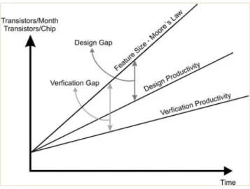
Figure 1.1 Design and Verification Gaps. Design productivity growth continues to remain lower than complexity growth - but this time around, it is verification time, not design time, that poses the challenge. A recent statistic showed that 60-70% of the entire product cycle for a complex
logic chip is dedicated to verification tasks [25]. . . 1
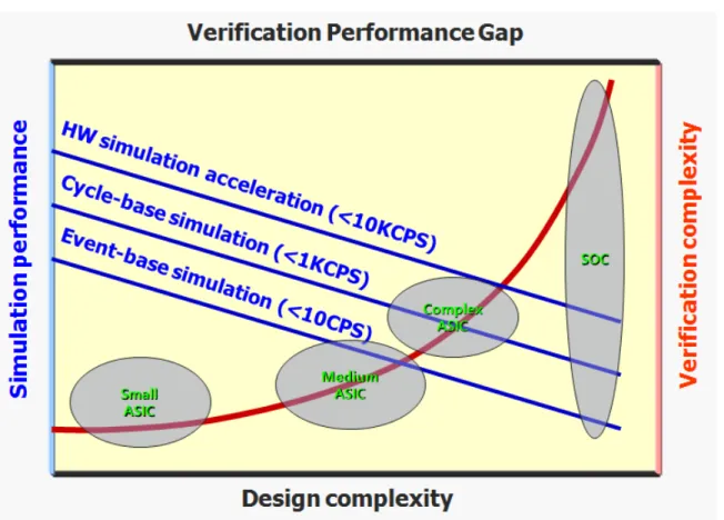
Figure 1.2 the verification gap from simulation point of view. Simulation is the main approach to design verification, and there are simulation plat-forms suitable for different abstraction levels. However, as integration level increases, simulation efficiency always decreases; during the re-quirement to thorough simulation increases. There is a widening gap between the required and available simulation performance [35]. . . 2
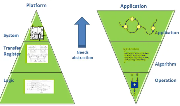
Figure 1.3 the structure of the thesis. . . 2
Figure 2.1 Example 1: Framework Example. . . 10
Figure 2.2 HW/SO design trade-off. . . 18
Figure 2.3 Typical use of CP optimizer [13]. . . 20
Figure 2.4 Elementary cumul function expressions([13]). . . 25
Figure 2.5 Example of alternative constraint in ILOG solver. . . 27
Figure 3.1 MPEG-4 and VOIP packet flow in MPSoC architecture. . . 30
Figure 3.2 A 2 x 2 regular mesh MPSoC architecture. . . 31
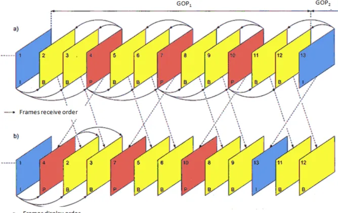
Figure 3.3 MPEG-4 frame dependencies ( The arrows display the dependants bet-ween frames decompressed. ) . . . 32
Figure 3.4 Upper picture: MPEG-4 and VOIP packet flow in MPSoC architec-ture - Lower picarchitec-ture: Application-specific topologies under test. IP denotes processor cores, pr private-Memories, and NI Network inter-face. . . 35
Figure 3.5 BeagleBone Black Considered flow. . . 38
Figure 3.6 BeagleBone Black board ([12]). . . 39
Figure 3.7 BeagleBone Black block digram. . . 41
Figure 4.1 Original and decompressed packets in the system floe chart . . . 46
Figure 4.2 Capacity constraints . . . 50
Figure 4.3 Alternative tasks constraints . . . 50
Figure 4.4 MPEG-4 Group Of Picture order and frame dependencies . . . 53
Figure 5.2 Results for MPEG4 and VOIP separately . . . 65
Figure 5.3 Results for MPEG4 and VOIP combined . . . 66
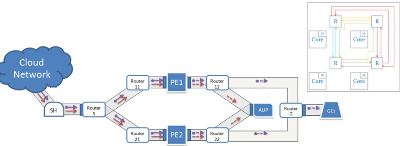
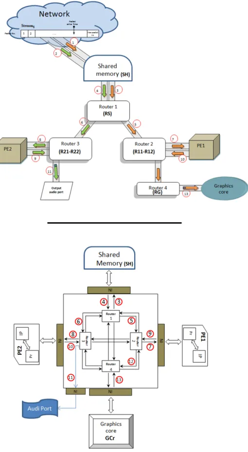
Figure 6.1 streaming applications flow in MPSoC industrial architecture. . . 69
Figure 6.2 DS-5 streaming Counters used to measure system performance. . . 72
Figure 6.3 Streamline Ds-5 Dhrystone application. . . 91
Figure 6.4 Streamline DS-5 WhestStone application. . . 92
Figure 6.5 Streamline for ice weasel applications browsing multiple web pages in a separate window. . . 96
Figure 6.6 Streamline for ice weasel application browsing multiple web pages in a separate tab. . . 96
Figure 6.7 Two different streamline analysis for MPlayer applications running lo-cal video with low decompression rate for newsletter program (Case b(c2)). . . 101
Figure 6.8 Two different streamline analysis for MPlayer application running local video with high decompression rate for football game (Case a(c1)). . . 102
Figure 6.9 Two different streamline analysis for MPlayer application running live stream video with high decompression rate for football game (Case g(c1)). . . 103
LIST OF ABBREVIATIONS
API Application Programming Interface ATPG Automatic Test-Pattern generator BDD Binary Decision Diagram
BW Band Width
CP Constraint Programming CSP constraint satisfaction problem CPU Central Processing Unit
DUT Design Under Test DSP Digital Signal Processing FSM Finite-State-Machine FIFO Frst In First Out GOP Group of Pictures
HW Hardware
HDL Hardware Description Language HVL Hardware Verification Languages IC Integrated Circuit
IDE Integrated Development Environment I/O Input/Output
IP Internet Protocol
MPEG Moving Picture Experts Group MPSoC Multiprocessor System-on-Chip MP Mathematical Programming NOC Network-on-Chip
OOP Object Oriented Programming OR Operations Research
OPL Optimization Programming Language PCI Peripheral Component Interconnect PAPS Periodic Admissible Parallel Schedules PE Processing Element
RT Real Time
SOC System On Chip
SW Software
TB Testbench
TDMA Time Division Multiple Access VLSI Very-Large-Scale Integration VOIP Voice Over Internet Protocol WCET Worst Cases Execution Time
CHAPTER 1 INTRODUCTION
Figure 1.1 Design and Verification Gaps. Design productivity growth continues to remain lower than complexity growth - but this time around, it is verification time, not design time, that poses the challenge. A recent statistic showed that 60-70% of the entire product cycle for a complex logic chip is dedicated to verification tasks [25].
The multiprocessor System-on-Chip (MPSoC) designs have become a very popular choice for modern embedded systems [41]. These designs use complex on-chip networks to integrate different programmable processor cores, specialized memories, and other components on a single chip. The parallel nature of MPSoCs makes verification a challenging task, in par-ticular for communication and multimedia applications. This is due to the non-functional constraints of hardware and software modules, such as processor speed, buffer size, energy budget, and scheduling policy [45], the combination of multiple applications.
System-level design and verification methodologies such as Constraint Programming (CP) have been introduced as a solution to handle the design complexity of embedded systems [45]. The power of CP comes from the fact that validity, quality, and test specification requirements for any system are naturally modeled through constraints, which are naturally represented as a Constraint Satisfaction Problem (CSP). In this work, we introduce a constraint-based scheduling model for concurrent streaming applications on MPSoCs with and without con-sidering processor scheduling policies.
unsatis-Figure 1.2 the verification gap from simulation point of view. Simulation is the main approach to design verification, and there are simulation platforms suitable for different abstraction levels. However, as integration level increases, simulation efficiency always decreases; during the requirement to thorough simulation increases. There is a widening gap between the required and available simulation performance [35].
fied application constraints. Also, we propose design optimization (e.g. buffer minimization) to increase the system efficiency and reduce its cost.
1.1 Problem statement
From the design complexity point of view, although the SoC paradigm is very beneficial—it has practically reduced designing a complex system to integrating pre-designed and reusable components – the verification of the SoC becomes the critical bottleneck in further improving SoC design productivity [40]. Generally speaking, verification refers to the practice of detect-ing errors in designs. Designs that are not thoroughly verified are not worth manufacturdetect-ing; and errors should be corrected as early as possible—correcting errors at a late stage could be forbiddingly costly.
Verification was regarded as the subservient issue compared with the implementation of a design. This view soon became invalid. The well-known Moore’s law suggests that the com-plexity of integrated circuits is growing at an exponential rate against time, whereas multiple sources claim the verification complexity is growing at a double-exponential rate, i.e., expo-nential with respect to Moore’s law. Figure 1.1 and 1.2 illustrate the growing verification gap between the integrated circuit (IC) verification capability and the IC design and man-ufacture capabilities. Nowadays about 50%-80% of the design time and efforts are spent in verification. It has become well known that verification is the main bottleneck in integrated circuit design [33].
The features of a typical SoC impose great challenges on SoC verification in two respects. – First, the large scale of hardware integration leads to sophisticated hardware-hardware
interactions. Since a SoC has multiple components, the interactions between them could give rise to emerging properties that are not present in any single component.
– Second, the introduction of software into hardware behavior leads to sophisticated hardware-software interactions. Since a SoC has at least one processor, hardware-software forms a new dimen-sion of the SoC behaviors and hence brings a new dimendimen-sion in verification.
This is why our research focuses on the process of test-case generation based on two different directions.
take the more active role of test-case control, especially parallelism management; the test bench, not the test-program, should take the relatively passive observation role.
– Interaction-Oriented Verification. The object-under-test should be the interactions among components, rather than the components themselves.
The main approach to verifying a design, especially a very complex one, is by simulation. Simulation is so important to verification that the term simulation and verification largely share the same meaning in practice. Simulation refers to the practice of running tests on models of a design before the design is actually manufactured. The term model refers to a presentation of the hardware under design in the form of software. The simulation approach inherently has the simulation performance issue. That is, simulation is a very time-consuming process, while VLSI designers are constantly under the time-to-market pressure. Fast and accurate simulation is always desired; however, being fast and being accurate are always competing metrics for simulation-based approaches. The verification gap viewed from the simulation point of view is shown in Figure 1.1 and 1.2.
As designs are becoming more complex, the requirement of thorough verification is soaring, whereas the performance of various simulation technologies is degrading. The simulation performance issue is more outstanding for SoC verification due to its high level of integra-tion. Due to the high design complexity and manufacturing cost, new system-level design methodologies for embedded systems have emerged to deal with the increasing time-to-market pressure.
At system-level, the concurrency or parallelism, among multiple components is the defining characteristics of a hardware system. The concurrency forms a new verification dimension. System-level bugs are usually discovered in corner cases where parallel processes interact with each other in an unexpected way. Resource-competition is an inevitable consequence of concurrency. Hardware components could show functional problems when competing with each other for resources, even if they have already passed component-level verification. Listed next are some potential bugs found at system-level:
– Interaction between blocks that are assumed verified. – Conflict in accessing shared resources.
– Arbitration problems and missing deadline. – Priority conflicts in tasks.
– Unexpected hardware/software sequences.
All these bugs are related to component-to-component interactions, especially to concurrent interactions with resource competitions. Therefore the key to system-level verification is to construct concurrency/resource-competition satisfactorily.
1.2 Contributions
The main contribution of this thesis is improved verification and exploration of system-level concurrency in MPSoCs. It addresses Constraint Programming (CP) as a powerful tool for the verification of performance metrics of MPSoCs.
We studied the possibility of creating a system-level scenario that takes into account the sys-tem level work-flow with respect to Syssys-tem resources and performance requirements, namely task deadlines, response time, CPU and memory usage, and buffer size. Specifically, we in-vestigate whether the behavior of different interactions among system components executing different tasks can be effectively re-expressed as a constraint-based scheduling problem over the space of possible inputs to the system, finding if we can address similar cases of failure using this model. Solving this problem means finding a better way to investigate and verify the System under verification in address a certain case of failure in a very early design stage and in a much more reasonable time.
The idea is to choose various applications with different input streams and different work-flow architectures, study its performance requirements with different order and interactions, and then see how it affects the system. Having this information helps defining a set of constraints to represent how each application should work on any architecture. This will be used in cre-ating different system-level scenarios. It gives the ability to explore different architectures, detect possible system failure at an early stage, and in some cases even suggest a proper solution. Note that this approach is not about the detection of bugs in the logic of the ap-plications.
Our proposed approach was tested with various applications, different input streams and different architectures. Results show that the methodology is able to identify system failure conditions in a fraction of the time needed by simulation-based verification. It gives the Test
Engineer the ability to explore the design space and deduce the best policy, also it helps choose the proper a recommended architecture for the applications running. We built our model for already built architectures in the market running chosen applications and compare our model results with the results coming from running the actual applications on the system. The research has produced the following publications:
– First Paper [16]: this paper contains the work introduced in Chapter 4. The main con-tribution of this work is to provide a technique to map a synthesised but still interesting MPSoC as a constraint scheduling problem and to generate interesting test cases based on streaming applications. These tests are capable of discovering corner cases that would cause system failure. The introduced model has a limitation of scaling. It has a large number of tasks, because it uses packets generated by the applications to represent its flow in the system.
– Second Paper [17]: this paper contains the work introduced in Chapter 5. This work re-solved the scaling problem we faced in the first model. Here we introduced a new way to decrease the number of tasks representing each application running in the system while respecting the same system and application constraints. To achieve this, we changed the way the application is mapped in the system from packets to frames. This proposal im-proved the model performance, covering more test cases, and running the application for longer periods of time on the system which make the results more accurate.
– Third Paper (pending): this paper contains the work introduced in Chapter 6. Here we deal with an industrial case study with a commercial application. We overcome the problem of representing hundreds of millions of instructions as a limited number of tasks running in the system. These tasks calculations are based on traffic generated by its applications. Also, we introduced new applications and studied how their overlapping with stream ap-plications did affect the system.
1.3 Organization
The main structure of the thesis is shown in Figure1.3
– Chapter 1: gives an introduction to the thesis, including the problem statement, contribu-tion and structure.
– Chapter 2: lays a firm background for further development of the thesis. The main topics include:
– Basic concepts give a brief explanation to Constraint Programming and Verification Technology focusing on the system level verification.
– Literature review of System-Level verification
– IBM CPLEX Optimizer the tool used in this thesis to create our model. It includes a brief explanation of Scheduling with IBM ILOG CPLEX Studio and IBM ILOG CPLEX Studio Search strategy which is the default strategy we used.
– Chapter 3 gives a description of MPSoC architecture platforms and applications considered in building the first two case studies described in Chapters 4 and 5. And the specifications of the industrial platform and applications used with the third case study in Chapter 6. – Chapters 4, 5 and, 6 have the explanation and discussion of the proposed constraint
pro-gramming model for each case study in two different sections:
– Constraint-Based Scheduling Approach: contains an explanation for the stream model and its decision variables followed by a description of each of the constraints and why we added them.
– Experimental results with a complete description and discussion of the model results. The strengths and weaknesses are also discussed.
CHAPTER 2 BACKGROUND AND LITERATURE REVIEW
With the increasing complexity in embedded products and the improvements in development technology, Multi-Processor System-On-Chip (MPSoC) architectures have become widespread. They can now be found in many complex real-time systems (e.g. cell phones, video process-ing or avionics). Theses systems usually share the same set of applications with a common well-characterized context. However, each possible set of applications that can be active con-currently in an MPSoC platform leads to a different use-case. And each use-case has to be verified and tested while meeting several additional design constraints (e.g. energy consump-tion or time-to-market). Therefore it takes a great amount of time for these applicaconsump-tions to be tested and optimized and, mechanisms to efficiently explore the different possible HW-SW design interactions in complete MPSoC systems are in great need. In this chapter we try to give a little bit of history of what have been done before and how this was affected by the work in this thesis.
As discussed in Chapter 1, we want to tackle the two major problems: the generation of test cases to verify the system and the interaction between the system components when different tasks are running on the platform. This chapter is divided into two parts: To start with, we discuss basics of embedded-system verification, system-level verification problems and its literature review. Because Constraint Programming is considered an important part of system-level verification researchers, the second part of this chapter focusses on Constraint Programming basics, approaches and, researchers on the generation of test cases for verifica-tion of mixed software/hardware systems.
2.1 Embedded System Verification 2.1.1 Verification Technology
The goal of verification is to ensure that the design meets the functional requirements as defined in the functional specification. Verification of SOC devices takes anywhere from 40 to 70 percent of the total development effort for the design. Some of the issues that arise are how much verification is enough, what strategies and technology options to use for ver-ification, and how to plan for and minimize verification time. These issues challenge both verification engineers and verification solution providers.
A wide variety of verification technology options are available within the industry. These options can be broadly categorized into two classifications [42]
– Simulation-based methods or dynamic verification. In this category, the verifica-tion engineers develop a set of tests known as test-cases to stress a given design. Hence, the design is often called design-under-test or DUT. A test-case could be a very abstract description of a scenario the DUT should be exercised in.
– Formal methods or static verification. This category is called static since no tests are needed. Instead, the verification engineer should provide design properties (the properties a correct design should have) in the form of temporal logic. The design is represented in Finite State Machine (FSM) form. Then a Binary Decision Diagram (BDD) based model-checking tool computes whether the design abides by the properties. If one property is violated, the tool will produce at least one counter example – a sequence of input to the FSM that leads to the violation of that property.
While formal verification techniques have their clear advantages, most notably the ability to formally prove functional correctness of the design, they can hardly cope with modern com-plex designs at the level of a single unit or larger. To this end, simulation-based verification, in which the design behavior is checked by simulating it over external inputs, accounts for roughly ninety percent of the overall verification efforts and resources. This is why the work in this thesis focuses on Simulation-based Verification and to be more specific on system level verification.
Simulation-based Verification and Stimuli Generation
The essence of simulation-based (or dynamic) verification is to test how the design conducts itself when confronted with challenging stimuli. Stimuli generation, in turn, deals with the problem of creating the appropriate stimuli in order to test the DUT as thoroughly as possible. The nature and abstract level of the stimuli depends on the object being tested and the level of verification. Automatic Test-Pattern Generator (ATPG) tools [37] test the manufacturing of circuits by applying sequences of lowest-level bit-vectors at the circuit’s input interfaces. A full processor can be tested by generating test programs in the assembly language of the processor. At the highest abstraction level, system level stimuli can include commands that
Figure 2.1 Example 1: Framework Example.
produce transactions involving multiple system devices.
A good stimulus first needs to be valid with respect to the requirements imposed by the DUT. It should also be of high quality in the sense that it tests the behaviour of the DUT in some desired circumstances to improve the coverage of the tested behaviour, reach chal-lenging corner cases, and hopefully trigger a bug. Also, the stimuli had better be able to expose the bug if it indeed occurs during the test execution (and not render it unobservable, for example, by masking its effects).
The most basic, technology-free method for generating stimuli is to write them by hand. Surprisingly enough, this is still being done, especially if there are only a few simple directed stimuli that are needed, or when there is no available technology to generate the type of stimuli required. Needless to say, this method is limited in capacity, expensive, error-prone, and often cannot achieve the precise stimuli that are required. A technology for automatic stimuli generation is therefore needed.
The generated stimuli, usually in the form of test programs, are designed to trigger architec-ture and micro-architecarchitec-ture events defined by a verification plan [20]. The input for a test program generator is a specification of a test template. An example of such a test template would be a set of tests that exercise the data cache of the processor and that are formed by a series of double-word store and load instructions. The generator produces a large number of distinct well-distributed test program instances that comply with the user’s specification. The variation among different instances is achieved through a large number of random deci-sions made during the generation process. In addition, generated test programs must meet
two inherent requirements: (1) tests must be valid, that is, their behaviour should be well defined by the specification of the verified system; (2) test programs should also be of high quality, in the sense that they should expand the coverage of the verified system and focus on potential bugs. Recently, technology has shifted toward constraint-based formulations of the generation task and generation schemes driven by solving constraint satisfaction problems (CSPs) [20].
2.1.2 System-Level Verification Challenges
At system level, the concurrency among components is the defining characteristic of the hard-ware system. Its bugs are usually discovered in corner cases where parallel processes interfere with each other in an unexpected way. Resource competition is an inevitable consequence of concurrency. HW components could show functional problems when competing with each other for resources, even if they have already passed component-level verification.
System Level Stimuli Generation has four challenges:
– Specifying system level scenarios in an abstract form while generating the required low level stimuli
– Generating coordinated system-level stimuli projected to each and every core in the system – Effectively handling configuration changes (e.g.: 2-way system vs. 8-way system)
– Adapting to core modifications and new cores (e.g.: PCI to PCIe)
Currently, neither formal methods nor general simulation-based approaches are dealing with the system-level behaviours such as concurrency/resource-competition satisfactorily.
Formal Methods
Formal methods are simply not in the position to discover system-level bugs due to the nature of these bugs, so the industry is depending less on formal methods [18].
– Bugs caused by implementation details: system-level bugs could arise from an in-accurate or a miss-interpreted design specification, as well as from the detailed im-plementation of that specification. Formal methods may suit well for the former, in which implementation details could be abstracted away. However, if the design is rep-resented as an FSM with implementation details, the model-checkers will not scale up.
– Control and data-intensive failures: system-level bugs often arise in scenarios in which data-intensive and control-intensive behaviours are loosely intertwined; whereas for-mal methods work best with control-intensive applications.
– Failures across components: it is often impossible to attribute a system-level bug to a particular hardware component; instead, the bug may be caused by the ill-matched behaviors of multiple components [24]. It will be very difficult and un-scalable for formal methods to deal with combined or communicating FSMs.
More importantly, the fact that the user is responsible to provide properties to formal tools is the fundamental barrier to applying formal methods on system-level verification. Hardware systems, which are made of multiple components and may be represented with implementation details, do not have fixed failure modes. Therefore, verification engineers are constantly faced with the difficult choice of “expecting something unexpected”. As a conse-quence, they cannot postulate those properties that they are yet to know.
Testbench based Simulation Generation
System-level verification essentially based on the simulation approach, in which tests are applied to the design-under-test (DUT) via a structure called testbench (TB). Yet, the current practices based on testbench (TB) construction have encountered some problems:
– The TB stimulates DUT and observes the response from the exterior of the DUT. This arise from the distinction between external and internal behaviours where the TB treats the DUT as a black box. It applies stimulation and observation from the outside of a DUT, so it is naturally difficult to force the TB to control and observe the DUT’s internal behaviours. There are white-box approaches, i.e., adding control and observation points around components inside a DUT, to supplement the black-box approach. However, we could argue that this approach is still black-box natured in the sense that the similar control and observation issues still exist at com-ponent level.
– The divergence between the techniques to develop DUTs and those to develop TBs rapidly becoming two distinct entities. In a word, a TB is more a software occurrence in the real world than a hardware structure in the simulated
world ([42]).
– The languages used to develop a DUT continues to be HDLs. In addition, for pre-cise simulation, the DUT should be described in the synthesisable subset of HDL constructs. A DUT is largely understood as a hardware structure in the simulated world.
– The languages used to develop a TB migrate to HVLs and other object-oriented programming (OOP) languages. These languages provide dynamic constructs to make possible dynamic connections. Still, being dynamic also means the loss of synthesisability. The state-of-the-art TBs require OOP paradigm or even beyond.
– Increasing TB complexity. When components are integrated into a system, new ca-pabilities have to be added in the TB to test the emerging properties caused by the integration. In this way TB complexity could grow faster than DUT complexity. This will eventually prevent us from relying on TB alone to verify a more complex DUT.
As we can see, the Testbench based Simulation Generation creates serious complications for system-level verification. It is very complex to take control and observation responsibili-ties; but in the end, it still does not touch the main challenging task of test generation.
Software.
Software (SW) may be responsible for the majority of the SoC functionalities, yet, soft-ware does not have a proper place in TB-Based verification methodologies.
– SW-based verification is naturally used in processor verification. In this case, SW is organised at the instruction-level and usually targets the micro-architecture of the processor-under-test. Therefore, this category of verification methodologies does not apply to system-level verification.
– SW-based tests are also found in SoC manufacturing-testing. Since the driving force of design verification and manufacturing testing are substantially different, those methods shed limited light on the area of SoC verification.
– The idea of “HW/SW co-verification” is practiced as running an operating system (OS) and application software on a SoC model for the purpose of software verifica-tion. Therefore, running these software components is the “liability” rather than the “asset” for the hardware team.
– SW in the form of hardware diagnostics programs could be interpreted as the “asset” to SoC verification. However, these diagnostics (a) are either too simplistic or too specific, and (b) are poorly automated and require manual development. So using this form of software cannot serve as a major verification approach.
Software is the valid testing factor alongside the DUT and the TB. For an SoC DUT, it is common practice for a verification engineer to write tests in the form of software snippets. This common practice actually demonstrates the software’s capabilities in controlling and observing a DUT. Although writing test cases in software is often treated as an ad-hoc verifi-cation technique, we should realise that the introduction of software in hardware verifiverifi-cation has overturned the traditional TB-Based verification problems.
2.1.3 Current Research on System-Level Verification
Simulation-based verification is a well-known method to determine the response time of embedded systems. Simulation is the process of mimicking key characteristics of a system or process. It can be performed at different levels of abstraction. At one end of the spectrum, one finds tools such as Wind River Simics ([36]) or ReSP ([6]) which simulate a complete system (software and hardware) in detail. Such simulators are used for low-level debugging or for hardware/software co-design. This type of simulation can trade off speed and accuracy: it can yield accurate timing analysis with long simulation time, or focus on speed by limiting its scope to functional simulation.
At the other end of the spectrum we find scheduling simulators, which abstract from the actual behaviour of the system and only analyze the scheduling of the system’s tasks, specified by key scheduling attributes and execution times ([42]).
System verification technology has recently shifted towards the use of Constraint Pro-gramming (CP) for random functional test generation. For example, several constraint-based generators were developed at IBM: X-Gen [19] for system-level verification, GenesysPE [1] at
the architecture level, Piparazzi [2] at microarchitecture level, FPGen [4] and DeepTrans [3] for hardware units, and SoCVer [31] for SoCs. These works use constraints both to describe the hardware system and to express which areas of the design should be tested. They also use randomness to achieve a balanced distribution of the generated test data in these areas. Results show this relatively new trend as a promising alternative to simulation-based verifi-cation of complex hardware systems.
Systems handling stream applications like MPEG-4 or VOIP, for example, define a pipeline work flow with strict ordering of data transfers between system components. Such systems typically employ a single controller core and a specific software model. Verification of these systems requires creating a system-level scenario that takes into account the system level workflow [31, 8, 34], with some random variance allowed.
Such systems are also decoupled, and allow a large variability in the interactions between the cores, supporting a large number of system configurations. It is important to verify the conjunction of functionalities of the different components, since errors are usually triggered by specific interactions. Some errors can only be exposed if the components interact locally in time and space, that is, if the interaction involves using the same resources at the same time. One also has to consider multiple system resources such as CPUs, disks, and network links that require coordinated scheduling to meet the end-to-end performance requirements of streaming applications.
In general, scheduling problems are computationally challenging, and have been sub-ject of active research in Constraint Programming (CP) and in Operations Research (OR) for many years [30].
Constraint programming has been used more specifically in the scheduling of task graphs on MPSoCs without violating computation capacity and communication bandwidth [7, 24], and for data-stream (or cyclic) scheduling [10]. Since [24, 10] proposes a global cumulative constraint for cyclic scheduling problems, they are not really applicable to our case. In our work we consider problems arising from different tasks scheduling needs and interleaving be-tween tasks applications at different timing. On the other handv [7] is more related. They tackle the problem of allocating and scheduling processors, communication channels and memories of multicore platform. They compare different approaches and results show that Constraint Programming is a proper tool for dealing with multi-task applications achieving
very good performance.
Verification of embedded streaming applications in communication and multimedia do-mains on MPSoCs has been widely explored by using the Synchronous Data Flow (SDF) model [29, 38]. Lee and Messerschmitt [29] first present general techniques to construct pe-riodic admissible parallel schedules (PAPS) on a limited number of multiprocessors. Govin-darajan et al. [21] propose a linear programming formulation to obtain maximal throughput and minimized buffer cost for SDF models without computation (number of processors) constraints. Eles et al. [18] first address the scheduling on distributed systems with commu-nication protocols optimization. Stuijk [38] propose a mapping and TDMA/list scheduling design flow for throughput constrained SDF applications on MPSoCs. Zhu [44] propose a design optimization framework for adaptive real-time streaming applications based on recon-figurable devices. They further investigate buffer minimization and task scheduling issues for streaming applications in [45]. In our work we took advantages of CSP to validate scheduling of embedded streaming applications on distributed systems. We used objective function to propose design optimization (e.g. buffer minimization - number of processors). We studied the effect can be caused by interaction between this applications and other type of applica-tions. Or, study the behaviour of the same application on different conditions (e.g. different frame rate or size).
We can see a big part of research on system level verification lately shifted toward Constraint Programming. For the problem of allocating and scheduling tasks on MPSoCs, which is the problem we target in this research, the major advantage of using CP is the clarity and understandability of the models. CP modeling is more flexible than other methods like the Mixed Integer Programming (MIP) on many challenging optimization problems, including mapping and scheduling [14].In the next few sections we will give some details on CP and how it fits in with system level verification for MPSoC running stream applications.
2.2 Constraint Programming
2.2.1 Basic Concepts of Constraint programming
Constraint Programming (CP) deals with modelling and solving CSPs. CSPs are math-ematical problems defined as a set of variables each with its own domain and whose state must satisfy a number of constraints or limitations constraints that restrict the values those variables can presume ([32]). For example, in an task/resource-scheduling problem, the
vari-ables may be the start and end time of each task on a certain resource, and a constraint may specify the maximum number of tasks can be run on one resource at the same time, or tasks sequence and dependant (one task can not be start before another end).
Mathematical formalism
Mathematically, a CSP P is a triplet (V, D, C) consisting of a set of variables V , a corre-sponding set of domains D, and a set of constraints C. A solution to a CSP is an assignment of a value to each variable out of the domain of the variable such that all constraints are satisfied. A CSP is satisfiable if it has at least one solution and unsatisfiable otherwise.
In the task/resource-scheduling example, assuming there are N tasks, we would have 2N variables: one start time variable and one end time variable for each task. The domain of the two variables may be the list of available hours for each of tasks period. Constraints may specify such things as deadline for any particular task, requirements on resource sizes, and tasks dependency. Mathematically, constraints are known as relations. A relation on a set of k variables is the list of all legal combinations of k values, each taken from the domain of the corresponding variables. For example, consider three variables a, b, c, with domains {1, 2}, {1, 2, 3}, {1, 2, 3}, respectively. A constraint requiring that the three variables assume different values may be represented by the mathematical relation {(1, 2, 3), (1, 3, 2), (2, 1, 3), (2, 3, 1) }
CSP modelling
CSP modelling is the process of translating a real-world constraint problem into a CSP. It involves identifying the variables in the problem, the variable domains (i.e., the values each variable can have before considering conflicts due to the constraints), and the constraints. There is usually more than one way to choose the variables and domains. For example, in the task/resource-scheduling problem, we could have chosen the variables to be all combinations of start-end dates of a task. Under this choice, the domains of all variables may be the names of the tasks plus ”null, ” signifying that no task is scheduled at this particular resource in a certain time.
2.2.2 Constraint Programming and System-Level Verification
Figure 2.2 HW/SO design trade-off.
Validity, quality, and test specification requirements are naturally modelled through constraints . Consider the example, Figure 2.1, for testing performance of concurrent stream-ing applications runnstream-ing on MPSoCs via simulation-based verification. Such tests have three main challenges which are:
1. creating inputs, or ’stimuli’ that are:
– valid according to the hardware specification and the simulation environment,
– interesting in the sense that they are likely to excite prone-to-bugs areas of the de-sign, and
– diverse.
2. Find the proper Trade-Offs in time, behavior and area in HW/SW design (Figure 2.2) with the proper abstraction level expressing both the complexity of applications and execution platforms
3. Analyze performance (ex: WCET ”Worst Case Execution Time”, Hard/Soft tasks dead-lines, resources limit, ...).
Item (1) is dealt with by modelling the entire hardware specification, as well as that of the simulation environment, as a set of mandatory constraints over the simulated variables (memory addresses, data transferred, processor instruction parameters, and so on). Item (2) is dealt with in two ways: first, generic expert knowledge is modelled as a set of soft, non-mandatory, constraints (for example, a soft constraint may require the result of operation a + b to be zero, because this is a known prone-to-bugs area of the floating point processing unit). Item (3) is dealt with by adding a target for the model to achieve like Minimize memory used or delays. In addition, the verification engineer, who is directly responsible for creating the stimuli, may add mandatory and non-mandatory constraints to any particular run, directing the stimuli into required scenarios.
Going back to Figure 2.2, having a stream application running on MPSoC. We have item (1) as processes execute in a data driven manner, and communicate with each other via FIFO channels as a mandatory constraint. And item (2) to decide the proper process size to be considered (i.e. frames, packets, ...). Item (3) can be an optimization issue such as the rate of displaced stream frames per second may be maximized or the buffer used minimized. Once all specifications are modelled, this set of mandatory and non-mandatory constraints can be fed into a constraint solver, which comes up with a solution to the con-straint problem in the form of a valid and interesting stimulus. In order to achieve item (3), the solver typically has a built-in diversification mechanism, for example, that several frames access the same cache block, thus causing contention on resources shared between different processors. For a CSP to drive test program generation, the program, or its building blocks, should be modelled as constraint networks. A random test program generator can, therefore, be viewed as a CSP solver. It constructs a CSP from the user requirements and the system model, and produces a large number of distinct program instances that satisfy the constraints.
Constraint satisfaction problems that represent test programs share several character-istics. Test program generation requires random, well-distributed solutions over the solution space [20, 9], as opposed to the traditional requirement of reaching a single solution, all solutions, or a ”best” solution [27]. Huge domains are the result of large address spaces in modern architectures. The combination of huge domains (e.g., 264 values), linear constraints
(e.g., a = b + c) and non-linear non-monotonic constraints (e.g., A = B ⊕ C, where A, B, and C are bit vectors, and ⊕ is the bit-wise XOR operation) make storing and operating on these domains a difficult task. Other characteristics include a hierarchy of hard and soft constraints and dynamic modelling (i.e., new variables being ”born” when values are assigned to other variables).
2.2.3 IBM CPLEX Optimizer
(CPLEX Optimization Studio supports the rapid development, deployment and mainte-nance of mathematical programming(MP) and constraint programming (CP) models from a powerful integrated development environment (IDE) built on the Optimization Programming Language (OPL), through programmatic APIs, or alternatively through third-party modeling environments [26].) IBM ILOG CPLEX CP Optimizer is a constraint programming (CP)
Figure 2.3 Typical use of CP optimizer [13].
optimizer for solving scheduling problems, it also help solving some combinatorial optimiza-tion problems that cannot be linearized and solved simply using tradioptimiza-tional mathematical programming methods (see Figure 2.3).
Scheduling with IBM ILOG CPLEX Studio
The CPLEX Optimization Studio provides easy and efficient access to CPLEX CP Optimizer features, which are specially chosen to solve detailed scheduling problems over fine-grained time. There are, for example, keywords mainly considered to represent such aspects as tasks and temporal constraints. It offers a workbench of modeling features in the CPLEX CP Optimizer engine that intuitively and naturally tackle the issues inherent in detailed scheduling problems from manufacturing, construction, driver scheduling, and more.
In a detailed scheduling problem, the most basic activity is assigning start and end times to an interval (interval here represent a task need to be scheduled in the system). The CPLEX CP Optimizer implementation is particularly useful for fine-grained scheduling. Scheduling problems also involve the management of minimal or maximal capacity constraints for resources over time and of alternative modes to perform a task.
A typical scheduling problem is defined by:
– A set of time interval definitions of activities, operations, or tasks to be completed, that might be optional or mandatory.
– A set of temporal constraints definitions of possible relationships between the start and end times of the intervals.
– A set of specialized constraints definitions of the complex relationships on a set of intervals due to the state and finite capacity of resources.
– A cost function: for instance, the time required to perform a set of tasks, cost for some optional tasks that are not executed or the penalty costs of delivering some tasks past a due date.
A scheduling model has the same format as other models in OPL:
– Data structure declarations. – Decision variable declarations. – Objective function.
– Constraint declarations.
OPL provides specialized variables, constraints and keywords designed for modeling scheduling problems.
Data structure declarations
Data declarations allow you to name your data so that you can reference it easily in your model. For example, if your data in a table defines the traffic running of one application at one system resource, you might want to call your item of data traf icij where i=1,..., noApps, j=1,..., noResources, where noApps is the number of applications in your model and noResources is the number of system resources. You tell OPL that your model uses this data by declaring:
int noApps = ...; int noResources = ...;
f loat traf ic[1..noApps][1..noResources] = ...;
Decision variable declarations
Variable declarations name and define the type of each variable in the model. For example, if you want to create a variable that equals the capacity of each resource used in the system, you can create a variable named capacityi where j=1,..., noResources:
dvar int + capacity[1..noResources];
The dvar keyword indicates that you are declaring a decision variable. Since int+ in-dicates that the variables are nonnegative, this statement declares an array of nonnegative integer variables.
For scheduling there are specific additional decision variables, namely interval: In OPL, activities, operations and tasks are represented as interval decision variables. An
in-terval has a start, an end, a length, and a size. An inin-terval variable allows for these values to be variable within the model. The start is the lower endpoint of the interval and the end is the upper endpoint of the interval. By default, the size is equal to the length, which is the difference between the end and the start of the interval. In general, the size is a lower bound on the length. Also, an interval variable may be optional, and whether or not an interval is present in the solution is represented by a decision variable. If an interval is not present in the solution, this means that any constraints on this interval acts like the interval is “not there.” The exact semantics will depend on the specific constraint.
dvar interval app1[tinT ask][rinResourc] size Duration[t] optional;
Other types exists but we did not use it in the scope of this thesis.
Objective function
The objective function is an expression that you want to optimize. This function must consist of variables and data that you have declared earlier in the model. We use objective function in our model to optimize our system. For example: determine the minimum cache size that can be used to successfully run the system. Or, get the minimum delay that can be used.
minimize sum(i in 1..noApps) startOf (app[i][1]); minimize sizOf (capacity[1]);
Constraint declarations
Precedence constraints Precedence constraints are common scheduling constraints used to restrict the relative position of interval variables in a solution. These constraints are used to specify when one interval variable must start or end with respect to the start or end time of another interval. A delay, fixed or variable, can be included. For example, if I have two different intervals a and b to be scheduled on a number of resources. Different precedence
constraints can be expressed in OPL.
dvarintervala; dvarintervalb;
List of precedence constraints in OPL:
– endBeforeStart: if we wants interval a ends before the start of interval b with at least x time units.
endBef oreStart(a, b, x);
– startBeforeEnd: if we wants interval a starts before the end of interval b with at least x time units.
startBef oreEnd(a, b, x);
– endAtStart: if we wants interval a ends at exactly the same time interval b starts.
endAtStart(a, b);
– endAtEnd: if we wants interval a ends at exactly the same time interval b ends.
endAtEnd(a, b);
startAtStart(a, b);
– startAtEnd: if we wants interval a starts at exactly the same time interval b ends.
startAtEnd(a, b);
Figure 2.4 Elementary cumul function expressions([13]).
Cumulative constraints A cumulative function expression, represented in IBM ILOG OPL by cumulFunction, can be used to model a resource usage function over time. This function can be computed as a sum of interval variable demands on a resource over time. An interval usually increases the cumulated resource usage function at its start time and decreases it when it releases the resource at its end time (pulse function).
For resources that can be produced and consumed by activities (for instance the con-tents of an inventory or a tank), the resource level can also be described as a function of time. A production activity will increase the resource level at the start or end time of the activity whereas a consuming activity will decrease it. The cumulated contribution of activities on the resource can be represented by a function of time, and constraints can be modeled on this function (for instance, a maximal or a safety level).
The value of the expression at any given moment is constrained to be nonnegative. A cu-mulative function expression can be modified with the atomic demand keywords (Figure 2.4):
– step, which increases or decreases the level of the function by a given amount at a given time;
– pulse, which increases or decreases the level of the function by a given amount for the length of a given interval variable or fixed intervals;
– stepAtStart, which increases or decreases the level of the function by a given amount at the start of a given interval variable;
– stepAtEnd, which increases or decreases the level of the function by a given amount at the end of a given interval variable.
A cumulative function expression can be constrained to model limited resource capacity by constraining that the function be less than or equal the capacity [13].
Example of step functions
There is an interval A, fixed in time. Interval A increases the level of the resource by x time units at the start of the interval, modeled by applying stepAtStart, created with Inter-val A and the Inter-value x, to the cumulative function:
cumulF unction f f = stepAtStart(A, x);
A more simpler example is to consider a function measuring a consumable resource. The level of the resource is zero, until time 2 when the value is increased to 4. This is modeled by modifying the cumulative function with the elementary cumulative function step at time 2:
cumulF unction f f = step(2, 4);
No overlap constraints To constrain the intervals in a sequence such that they: – Are ordered in time corresponding to the order in the sequence.
– Do not overlap.
– Respect transition times
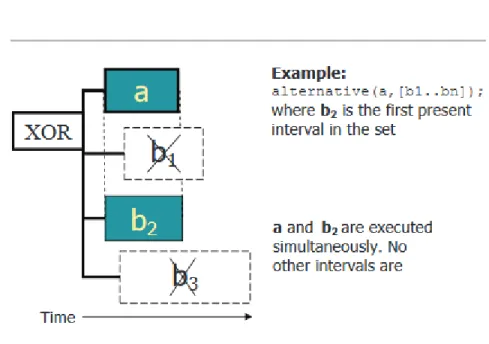
Figure 2.5 Example of alternative constraint in ILOG solver.
Alternative constraints An alternative constraint between an interval decision variable a and a set of interval decision variables B states that interval a is executed if and only if exactly one of the members of B is executed. In that case, the two tasks are synchronized. That is, interval a starts together with an interval from set B and ends together with it (Figure 2.5 ).
This type of constraint used in our system to represent the alternative resources that can be used by an application. Other types exists but we did not use them in the scope of this thesis.
IBM ILOG CPLEX Studio Search Strategy
Scheduling can be viewed either as a constraint satisfaction problem or as a constraint optimization problem. When we think of scheduling as a constraint satisfaction problem, our aim is to find a schedule that satisfies the constraints, whatever they may be. When we think of scheduling as an optimization problem, our aim is to find a schedule that is optimal or close to optimal with respect to a given optimization criterion. The optimization criteria usually relate to time, capacity, and sequence: typically the makespan, tardiness, peak capacity, or transition cost.
In our model we used the default search strategies recommended by IBM ILOG CPLEX scheduler. Its automatic search combines Large Neighbourhood Search with a portfolio of neighbourhoods and completion strategies together with Machine Learning techniques to converge on the most efficient neighbourhoods and completion strategies for the problem being solved [28]
CHAPTER 3 MOTIVATIONAL EXAMPLES
In system level design, it is essential to capture the functional behaviour and architec-tural characteristics independently for performance analysis and design space exploration. The resources we need to allocate and schedule in MPSoCs are heterogeneous: they include processing (micro-processors, DSPs, hardware accelerators), storage (i.e. on-chip memories) and communication (i.e. on-chip buses and I/Os) elements.
The embedded system requirements for distributed embedded systems (DES) can be divided into different groups which each impose a number of constraints on the scheduling problem. The functional behaviour of a embedded system is determined by the tasks and resources that constitute the system. Typical functional behaviour requirements are those that control task execution order or task allocation, that is, how a task should execute. An embedded system also have temporal behaviour requirements in addition to the functional ones. The temporal behaviour of a task depends mainly on the environment (sensors, ac-tuators or other tasks) that the task interacts with, that is, when a task should execute. These requirements directly affect the modelling of the application tasks and consequently the construction of the scheduling constraints.
Apart from mere software requirements, it is also a practical consideration that the development of embedded systems is made cost-effective so as to allow for mass-production of the system. That is why development using off-the-shelf hardware components has become a viable alternative in modern designs. Other practical aspects of embedded system design encompass the introduction of weight and power-consumption requirements. This means that cost, performance and various physical characteristics of the hardware components (proces-sors, memory and buses) need to be conveyed to the constraint construction process ([15]).
In this thesis, we have developed a scheduling framework based on constraint pro-gramming which attempts to tackle these needs. We mapped streaming applications onto a target Multi-Processor System-on-Chip (MPSoC) architecture as a constraint-based schedul-ing problem. We introduced three motivated examples discussed in Chapters 4, 5 and, 6. The first two examples discuss mapping streaming applications on a synthesis MPSoC sys-tem architecture in two different ways. The third example discussed mapping streaming applications on a industrial MPSoC system architecture. Further more, introduced more
applications into the system. This chapter introduces preliminaries of the streaming appli-cation, the architecture platforms, and a declarative constraint programming paradigm used in this thesis.
3.1 Motivative Examples One and Two
Figure 3.1 MPEG-4 and VOIP packet flow in MPSoC architecture.
These two examples considered MPEG-4 and VOIP as the two streaming applications mapped into the DUT (see Figure 3.1). Both applications have a significant impact on the traffic through the system. They have a bounded flow control with synchronization restric-tion and, minimum accepted performance. This is why it can be used in creating a complex scenarios used to discover interesting corner cases detected onto the DUT.
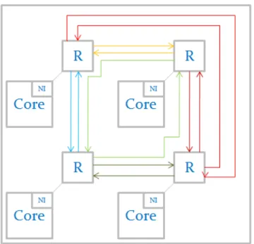
For the DUT we consider the regular 2-D mesh Network On Chip (NoC). It is simple but can be scaled easily (Figure 3.2).
As a case study, the MPEG4 was tested with five different standard frame sizes (QCIF, SDTV, HDTV, HDTV1, and HDTV2) where frameSize = pixelDepth × Width × Height. The VOIP application was tested in two different cases: a non-restricted delay case which represents applications with buffering flexibility (such as messaging), and a restricted delay case for applications with hard deadlines and quality assurance.
Figure 3.2 A 2 x 2 regular mesh MPSoC architecture.
application more realistic and allows the use of different streams with different data rates.
In the following paragraphs we will give a brief description of the nature of each ap-plication and constrains it forces. The details of the DUT and how it was represented in the CSP model. A detailed discussion for each application will be provided in the following chapters.
3.1.1 Streaming Applications For Synthesis Case MPEG-4:
Our first application is MPEG-4. The MPEG standard defines four distinct pictures en-coding: Intra-coded Picture (I-Picture), Predictive-Coded Picture (P-Picture), Bidirectional-Predictive-Coded Picture (B-Picture) and DC-Coded Picture (D-Picture). The I-Picture is coded using information only from the picture itself. The P-Picture is coded using motion compensation prediction in reference to a previous I-Picture or another P-Picture. B-Picture is coded in reference to either previous or future I-Pictures or P-Pictures. Finally, the D-Picture stores the DC component of each DCT block. The I, B and P pictures are arranged in a periodic pattern known as a Group of Pictures (GOP). Figure 3.3 shows the GOP of MPEG-4 video that we used, and the relationships among pictures. The MPEG-4 Group of
Figure 3.3 MPEG-4 frame dependencies ( The arrows display the dependants between frames decompressed. )
![Figure 2.4 Elementary cumul function expressions([13]).](https://thumb-eu.123doks.com/thumbv2/123doknet/2329680.31387/40.918.223.686.383.834/figure-elementary-cumul-function-expressions.webp)
![Figure 3.6 BeagleBone Black board ([12]).](https://thumb-eu.123doks.com/thumbv2/123doknet/2329680.31387/54.918.318.597.335.797/figure-beaglebone-black-board.webp)
