Session 7
Special test
Special test
Cryo-optical test of the PLANCK reflectors
Author(s):
S. Roose, A. Cucchiaro
(Centre Spatial de Liège)
Summary
• 1.Project Historical Background
• 2.Overall Description
• 3.Test results
1. Project Historical Background
• PLANCK reflectors: 2 CFRP off -axis ellipsoids (Primary and secondary reflector)
• Measure relative SFE difference (293K and 50K) measurement method with a resolution of
about 1 m (small deformations) on a SFE characterised by high SFE slopes at cryo-genic
temperature (1 mrad) with INFRARED INTERFEROMETRY
WFE reconstruction simulation of the Primary reflector,
through the CSL IR interferometer, based on expected deformation at 50 K, 512 by 512 pixels detector
2.1. Overall Description: Secondary reflector (Single pass interferometer)
O M2 O M2 C F Thermal shroud Reflector support Illumination opticsInterferometer cavity bench
Planck SR
Collecting optics
Optical bench Vacuum flange with
3.1. Test results Secondary reflector QM: Full aperture test
3.2. Test results: Secondary reflector QM and FM reduced field test
increased resolution derive new estimate for the slopes = 2 mrad
PLANCK SECONDARY MIRROR - FLIGHT MODEL - REDUCED PUPIL TEST - FM 1
name_ref"SRFM_1_1_293K_08DEC04_ZOOM1x_MOYENNE_REM9_corrige facteur 2.TXT"
name"SRFM_1_1_50K_17DEC04_ZOOM1x_MOYENNE_REM9_corrige facteur 2.TXT"
eti diff( )5.023 max diff( )15.01 min diff( )18.864 µm WFE
di2 dj1 1210 8 6 4 2 0 2 4 6 8 1012 450 400 350 300 250 200 150 100 50 0 k diffk colonne
tabmin tab( ) max tab( )min tab( )255
12 108 6 4 20 2 4 6 8 10 12 diffligne k ligne 210 colonne245
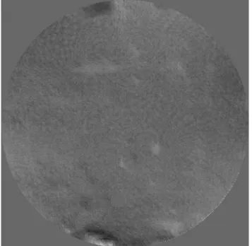
WFE difference between 293 K -50 K Secondary reflector FM on central aperture
• Test results Secondary Reflector
FM: New optical design
Increased slope collection: larger optics (4 inch diameter)
Increased resolution: stitching to form
3.4. Test results: Secondary reflector FM
Stitched aperture validation-compare interferometry with 3D dataPLANCK SECONDARY MIRROR - FLIGHT MODEL ASED measurements projected through all optical system
eti R( )10.261 max R( )62.536 min R( )53.934 µm WFE
50 25 0 25 50 700 650 600 550 500 450 400 350 300 250 200 150 100 50 0 k k Rk colonne Ik colonne fig tabR( ) 50 ligne 342 colonne 272 0.072 0.049
PLANCK SECONDARY MIRROR - FLIGHT MODEL - test 2
name "SRFM_2_1_295K_26JUN05_3STIT.mca"
eti I( )10.788 max I( )82.439 min I( )47.24 µm WFE
50 25 0 25 50 700 650 600 550 500 450 400 350 300 250 200 150 100 50 0 k k Ik colonne Rk colonne fig tabI( ) 50 ligne 342 colonne 272 3.979 3.592
ligne 342 30 fig tab( ) 30 15 0 15 30 700 650 600 550 500 450 400 350 300 250 200 150 100 50 0 k Dk colonne µm WFE min D( )59.909 max D( )50.322
eti D( )8.472 eti D( )0.17 max D( )2.972 min D( )3.108 waves WFE
2 1 0 1 2 700 650 600 550 500 450 400 350 300 250 200 150 100 50 0 k Dk colonne fig D0( ) 2 ligne 338 colonne 97
fig sphe( ) max sphe( )6.871
Tdimin diff( ) max diff( )min diff( )255
20 10 0 10 20 511 383.25 255.5 127.75 0 k diffk col 0 50 100 150 200 250 300 350 400 450 500 20 10 0 10 20 difflig k k name_r "PRFM_1_1_298K_2MAY05_ZOOM2x_01" name"PRFM_1_2_170K_8MAY05_ZOOM2x_pup1_OPD_1"
DIFFERENCE : NAME - NAME_R
PLANCK PRIMARY REFLECTOR FLIGHT MODEL PUPIL 1
1200 1100 1000 900 800 700 600 500 400 300 200 100 0 k 0 100 200 300 400 500 600 700 800 900 1000 1100 1200 1300 30 15 0 difflig k k Primary reflector Stitched full aperture:
4. Lessons Learned
Are the Planck reflector tests a generic case for the future optical testing cases? More and more for microwave to sub-mm reflectors: require testing!
-Slopes (non optical surfaces)
-1-10 micron metrology resolution -high spatial sampling rate < 5 mm
-non-contact measurement at very high (> 330 K) or very low T<90 K)
Commercial of the shelf measurement methods do not meet all requirements! (no market for it)
-3D machine (drawbacks: non vacuum, stable T, low sampling rate)
Reflector development needs to consider testing problem very early in the project! Why?
-thermal-elastic models do not tell the absolute truth: over-sizing the metrology tool might be necessary (increase test complexity). (PLANCK reflectors: wrong starting hypotheses in the assessment of commercial IR interferometry feasibility)
-allow to iterate with small scale test and metrology which addresses the hard-points. (PLANCK reflectors reduced field test)
-accept the non-universality of a method: divide and conquer, develop several simple test (PLANCK reflectors: SFE with interferometry (CSL) and global shape with