RESEARCH PROGRAMME OF THE RESEARCH FUND FOR COAL AND STEEL STEELRTD
Project carried out with a financial grant of the Research Programme of the Research Fund for Coal and Steel
DRAFT-FINAL REPORT
Technical Report N° 07 Issued on 30/03/2012
Period of Reference 01/07/2008 – 31/12/2011
Technical Group TG8
D
ESIGN AND
I
NTEGRITY
A
SSESSMENT OF
H
IGH
S
TRENGTH
T
UBULAR
S
TRUCTURES FOR
E
XTREME
L
OADING
C
ONDITIONS
Project Acronym: HITUBES
Grant Agreement Number: RFSR-CT-2008-00035
Beneficiaries : University of Trento, Italy
Centro Sviluppo Materiali, Italy
Instituto de Soldadura e Qualidade, Portugal Fundacion ITMA, Spain
Korrosions Och Metallforskningsinstitutet AB, Sweden Université de Liège, Belgium
University of Thessaly, Greece
Coordinator: Oreste S. Bursi, University of Trento
Authors: Oreste. S. Bursi (UTRE), Anil Kumar (UTRE)
Giuseppe Demofonti (CSM), Giuliana Zilli (CSM), Gian Marco Tamponi (CSM), Jan Ferino (CSM)
Helena Guvaia (ISQ), Carlos Maia (ISQ)
Sergio Rivera (ITMA), Ricardo Alvarez (ITMA), Ricardo Lezcano (ITMA)
Eva Johansson (KIMAB), Nuria Fuertes (KIMAB), Jean-Pierre Jaspart (ULGG), Jean-François Demonceau (ULGG), Long Van Hoang (ULGG), Ly Dong Phuong Lam (ULGG)
Spyros Karamanos (UTHESSA), Philip Perdikaris (UTHESSA), Aglaia Pournara (UTHESSA), George Varelis
(UTHESSA), Charis Papatheocharis (UTHESSA) Daniele Maio (StahlbauPichler), Manuel Sommariva
Distribution list
Chairman
Expert Name: Mr Louis-Guy CAJOT Organisation: ARCELOR PROFIL
ARCELORMITTAL BELVAL & DIFFERDANGE S.A. Members
Expert Name: Ms Nancy BADDOO Organisation: SCI
THE STEEL CONSTRUCTION INSTITUTE LBG Expert Name: Prof. Darko BEG
Organisation: UNIV LJUBLJANA UNIVERZA V LJUBLJANI
Expert Name: Prof. Antonio Augusto FERNANDES Organisation: UNIV PORTO
UNIVERSIDADE DO PORTO
Expert Name: Mr Anthony KARAMANOS Organisation: A.S. KARAMANOS
A.S. KARAMANOS & ASSOCIATES Expert Name: Prof. Andrzej KLIMPEL Organisation: SUT
SILESIAN UNIVERSITY OF TECHNOLOGY - POLITECHNIKA SLASKA
Expert Name: Mr Jouko KOUHI Organisation: FCSA
FINNISH CONSTRUCTIONAL STEELWORK ASSOCIATION
Expert Name: Prof. Joaquín ORDIERES MERE Organisation: UPM
UNIVERSIDAD POLITÉCNICA DE MADRID Expert Name: Dr. Walter SALVATORE
Organisation: UNIV PISA
UNIVERSITA DI PISA - DIPARTAMENTO INGEGNERIA CIVILE
Members (not reimbursed)
Expert Name: Mr Adam BANNISTER Organisation: TATA STEEL UK
TATA STEEL UK LTD - SWINDEN TECHNOLOGY CENTRE
Expert Name: Mr Thierry BRAINE-BONNAIRE Organisation: ARCELOR France
ARCELOR France SA
Expert Name: Dr.-Ing. Giuseppe DEMOFONTI Organisation: CSM
CENTRO SVILUPPO MATERIALI SPA Expert Name: Dr. Gerhard KNAUF Organisation: SZMF
TABLE OF CONTENT
DISTRIBUTION LIST ... 2
ABSTRACT ... 5
PROJECT OVERVIEW ... 6
FINAL SUMMARY ... 7
WP1: Review on test data and design procedures on tubular members and connections and Bayesian approaches for probabilistic risk assessment ... 7
WP2: Extreme forces and stresses on foot- cycle-bridges, railway bridges and monitoring of footbridges ... 9
WP3: Mechanical characterization of HSS and inelastic behaviour of HSS tubular members ... 10
WP4: Performance of HSS welded and bolted connections ... 11
WP5: Numerical simulations of tubular connections; parametric study ... 13
WP6: Numerical simulations of tubular members and structures; parametric study ... 14
WP7: Development of design guidelines and recommendations for high strength tubular structures ... 15
WP8: Project coordination ... 17
Conclusions and main results ... 17
List of deliverables of the project: ... 18
SCIENTIFIC AND TECHNICAL DESCRIPTION OF THE RESULTS ... 18
Objectives of the project ... 18
Comparison of initially planned activities and work accomplished ... 19
Description of activities and discussion ... 19
WP1: Review on test data and design procedures on tubular members and connections and Bayesian approaches for probabilistic risk assessment ... 19
WP2: Extreme forces and stresses on foot- cycle-bridges, railway bridges and monitoring ... 22
WP3: Inelastic behaviour and buckling performance of HSS tubular members ... 33
WP4: Performance of HSS welded and bolted connections ... 41
WP5: Numerical simulations of tubular connections and parametric study ... 51
WP6: Numerical simulations of tubular members; parametric study ... 57
WP7: Development of design guidelines and recommendations for high strength tubular structures ... 65
WP8 Project coordination ... 72
Conclusions ... 74
Exploitation and impact of the research results ... 74
List of Publications ... 75
List of figures ... 75
List of tables ... 79
List of acronyms and abbreviations ... 80
List of References ... 81
APPENDICES ... 85
APPENDIX A: LITERATURE REVIEW ... 85
APPENDIX B: IDENTIFICATION AND MONITORING OF CASE STUDIES ... 93
APPENDIX C: TESTS ON MATERIALS AND MEMBERS ... 109
APPENDIX D: TESTS ON WELD MATERIALS AND CONNECTIONS ... 118
APPENDIX E: NUMERICAL SIMULATIONS OF WELDED AND BOLTED CONNECTIONS 130 APPENDIX F: NUMERICAL SIMULATIONS OF MEMBERS AND CASE STUDIES ... 137
APPENDIX G: DESIGN GUIDELINES AND RECOMMENDATIONS ... 146
APPENDIX H: STANDARD TEST PROTOCOLS, SWOT ANALYSIS & MONITORING ... 155
A copy of the signed “Technical Annex” (Annex I to the Grant Agreement) or its latest signed amended version if applicable ... 158
Abstract
High Strength Steel (HSS) characterized by yield strength ranging between 500MPa to 700MPa has been available for many years. However, its use in onshore engineering is quite restrictive. Reasons were threefold: i) Eurocodes covered steels with yield strength up to 460MPa; ii) higher costs than regular steel; iii) lack of conceptual design with HSS. Nonetheless very recently, there has been a growing trend for the use of HSS in tubular structures thanks to Eurocode 3 Part 1-12 (2006), that extended its scope to steel grades up to S690/S700MC. Along this line, the HITUBES project intended to develop performance-based designs and assessment procedures to make full use of HSS tubes up to S700MC for structures subject also to extreme repeated loads; in fact Eurocode 3 Part 1-12 imposes many limitations at the material, structural and design level. The ambitious targets are to increase the performance of tubular structures, reduce weights, construction and operating costs.
The project covered the period 01/07/2008-31/12/2011, and main research work focussed on several aspects listed herein: literature survey; selection of finite element-based and identification dynamic analysis codes; selection of realistic Case Studies and FE analysis for the evaluation of actions and stresses; structural identification and health monitoring of a cable-stay and arch footbridges; tests planning and execution including welding procedure specifications; simulations of welded and bolted connections under monotonic, low-cycle and high-cycle fatigue loadings; simulation of Case studies and reliability analysis for quantification of realistic performance scenarios; SWOT analysis and monitoring of project activities.
Project Overview
A brief overview of the project for the period 01 July 2008 to 31 December 2011 is presented in Table 1. Table1: Final project overview
CATEGORY OF RESEARCH
(COAL /STEEL): STEEL
TECHNICAL GROUP: TG8
REFERENCE PERIOD: 01/07/2008-31/12/2011
GRANT AGREEMENT N°: RFSR-CT-2008-00035
TITLE:
DESIGN AND INTEGRITY ASSESSMENT OF HIGH STRENGTH
TUBULAR STRUCTURES FOR EXTREME LOADING
CONDITIONS
BENEFICIARIES: University of Trento, Italy
Centro Sviluppo Materiali, Italy
Instituto de Soldadura e Qualidade, Portugal Fundacion ITMA, Spain
Swerea KIMAB AB, Sweden Université de Liège, Belgium University of Thessaly, Greece
COMMENCEMENT DATE: 01 July 2008
COMPLETION DATE: 31 December 2011
WORK UNDERTAKEN:
o Literature survey and selection of case studies
o Selection of FE codes, simulations and
investigations on case studies
o Structural identification and monitoring of footbridges
o Tests on HSS materials and welds also considering post-weld treatment
o Tests on HSS tubular members and welded and bolted connections
o Numerical simulations on HSS tubular members, tubular welded and bolted connections
o Simulation on footbridges and fatigue checks o Development of design guidelines and reliability
evaluation
o Standard protocols, SWOT analysis and monitoring of project activities
MAIN RESULTS:
o Literature survey completed, case studies selected o FE and identification codes chosen, analysis and
investigation on case studies completed
o Identification and monitoring of the two footbridges completed
o Tests completed
o Numerical simulations completed
o Design guidelines and reliability assessment developed
o Efficient management process set
o Standard protocols, SWOT analysis made o Monitoring of the project completed FUTURE WORK TO BE UNDERTAKEN:
ON SCHEDULE (YES /NO): YES
PROBLEMS ENCOUNTERED: - Difficulty in the provision of HSS TS 590J2H
tube material in small quantity (193.7 x 10 mm tubes – about 3.5 tons; 355.6 x 12.5 mm tubes – about 1.5 tons);
- Wind turbines not studied. CORRECTION – ACTIONS
(USE OF A TABLE IS RECOMMENDED):
- Tenaris Dalmine agreed and provided the small quantity of steel tubes;
- Technical annex was amended
PUBLICATIONS – PATENTS :
In summary: 10 papers and 1 book; 2 papers published on international journals, 3 papers under preparation; 5 on international conferences. See Section List of Publications.
BUDGET INFORMATION PER BENEFICIARY:
Based on overall costs (independently from EU financial contribution) BENEFICIARY
(incl. coordinator)
Total amount spent to date (€)*
Total allowable cost (€) as foreseen in Grant Agreement
UTRE
404300.38
372907
CSM
203223.90
186799
ISQ
169826
ITMA
176416.20
174014
KIMAB
183883.60
166809
ULGG
186276.12
186530
UTHESSA
169077.69
175612
Final summary
WP1: Review on test data and design procedures on tubular members and connections and Bayesian approaches for probabilistic risk assessment
approaches for the development of time dependent formulations in order to perform probabilistic risk assessments; e) choice of output-only identification techniques.
The bibliographic review was made at the beginning of the project in order to have knowledge of conceptual design, standards and test methods relevant to HSS tubular members, joints and connections mainly employed for selected Case Studies. The main results of this work package are summarized here. They are also widely reported in Section WP1 of Description of Activities and Discussion, in Appendix A and relevant Deliverables D1.1-D1.4 listed in the Amended Technical Annex.
From the state of the art relevant to the use of HSS for onshore construction [1], it is clear that Europe is lagging behind with respect to USA and Japan in spite of the fact that several applications in constructions are cost effective. In detail, we restricted our scope to constructions made with Circular Hollow Sections (CHS) that result to be very competitive in terms of strength relevant to compression, tension and bending and torsion. Moreover, the CHS represents the optimal shape for elements subject to wind and sea loading owing to the low drag coefficient. Nonetheless, we considered also the Nomi footbridge which is characterized by a Rectangular Hollow Sections (RHS) arch. Due to higher cost of tubular members, about 15 per cent more with respect to open sections, and HSS, up to 30 per cent more for S690 with respect to S355, sometimes it is wise just to change the material to a higher grade in a small part of the structure, in order to achieve weight savings. Nonetheless, in many cases it is necessary to change the conceptual design of a structure in order to make full use of HSS. In fact, buckling, fatigue and deflection criteria often set limits for steel grade used. Though a working group within CEN/TC250/SC3 recently issued Part 1-12 of Eurocode 3 in order to make easier for designers and steel contractors the choice of HSS, still several problems remain. Basically, elastic analysis should be used though plastic resistance would be better. For joints there are restrictions with reduction factors, for instance 0.8, for strength design methods that make use of large plastic deformations. For welded connections undermatched electrodes are allowed. Within all these uncertainties, to collect and evaluate test data on members, joints and connections under extreme loadings as well as to extract realistic specimens to be tested, the following two main case studies were selected:
1. the cable-stay footbridge “Ponte del mare” Pescara, Italy. 2. The Landegem Railway Bridge, Belgium.
The basis for selection of two different types of bridges was that on one hand, the footbridge was mainly subject to elastic or possible low-cycle fatigue behaviour owing to excessive wind and pedestrian loadings; in fact, high-cycle fatigue check were carried out for wind and pedestrians, and all checks were satisfied; on the other hand the railway bridge was mainly subject to high-cycle fatigue loading owing to loads caused by passage of railway vehicles. It was expected that the study of structures subject to two different types of loadings would provide a better comparative understanding of the behaviour of structures, tubular members and joints made of HSS, including welding, bolting, etc. Due to higher cost of HSS, several bridges use tubular members with standard steel. In this respect, other two footbridges endowed with tubular members, i.e. the S. Michele footbridge and the Nomi footbridge, both located nearby Trento were selected and analysed. In particular: i) the twin tubular arch foot-cycle bridge at S. Michele (Trento) is characterized by S460 CHS arches; ii) the tilted bowstring arch foot-cycle bridge at Nomi (Trento) is endowed with a RHS bowstring arch. These bridges were also selected for fatigue model developments treated in Task 6.3, to reply to some open question left by the HIVOSS project [2].
The aforementioned activities and results allowed some brief conclusions to be drawn. Tubular members are very popular in bridge structures mainly for aesthetic and mechanical reasons. CHS members are preferred to RHS also for aerodynamic problems. With regard to steel grade and when strength dominates structural design, S355 and S460 are much more preferred with respect to S500 or higher grades both for costs and grade availability reasons. We understood that steel mills tend to use HSS for specific applications, e.g. tower cranes made of CHS with S690 or so, and therefore, also their adaptation to different grades is limited -taking into account material certification problems too-. With regard to structural design with HSS, though Part 1-12 of Eurocode 1993 was issued, the use of HSS both at the conceptual design level and at the checking level of members, joints, etc. remains difficult when extreme conditions in terms of actions and stresses are present. From a corrosion viewpoint, one serious drawback of HSS is its increased risk of hydrogen-related Stress Corrosion Cracking (SCC), or hydrogen embrittlement. The literature review indicates that this limit state can be reached for a suitable combination of material properties, environmental effects and stress conditions. Aggressive environmental effects, e.g. sea water, steered us to the selection of the “Ponte del mare” footbridge.
With regard to Bayesian techniques, Bridge Management Systems have become increasingly sophisticated over the past decade and provide valuable information about the structural condition of several bridges. At the same time, reliability methods have gained increasing prominence and are used to forecast life-cycle performance over many decades of structural life. In this context, reliability analyses can be updated with Bayesian techniques when inspection results are available. Nonetheless, available literature mainly focussed on reinforced concrete bridge superstructures.
Finally, modal analysis involving output-only measurements present a challenge that requires the use of special modal identification technique, which can deal with very small magnitude of ambient vibration contaminated by noise. There are two complementary modal analysis methods as rather simple Peak Picking (PP) method in frequency domain and more advanced stochastic subspace identification (SSI) method in time domain. The SSI technique can detect frequencies that may possibly be missed by the PP method and gives a more reasonable mode shapes in most cases. To be able to trace non-linear phenomena that change with time, also short-time Fourier transform techniques can be used. The choice of a time-frequency (TF) technique is made because of its robustness, i.e. its capability to clearly identify: i) signal events which manifest during a short time interval (time localization); ii) signal components which are concentrated at particular Fourier frequencies, such as sinusoids (frequency localization). We used both SSI and TF techniques in “Ponte del mare” mainly to capture the non-linear on-off behaviour of dampers used to reduce potential flutter phenomena and introduce damping. WP2: Extreme forces and stresses on foot- cycle-bridges, railway bridges and monitoring of footbridges
The main objectives of WP2 were: a) the selection of FE codes used to perform analyses to obtain extreme forces and relevant stresses; b) to perform the aforementioned analyses; c) to further justify the choices of Case Studies also on the basis of calculations and preliminary experimental data; d) to perform both system identification and structural health monitoring of footbridges “Ponte del mare” and “S. Michele”, respectively. At this stage, we note that the wind turbine was not chosen as a possible case study owing to the variable tube cross-sections of the mast. The tube of the mast is seam and typically, the manufacturer ‘Tenaris Dalmine’ only produces seamless tubes with constant cross-sections. Hence, the study on the chosen wind turbine was abandoned. Main results of this work package are summarized here. They are also widely reported in Section WP2 of Description of Activities and Discussion, in Appendix B and relevant Deliverables D2.1 and D2.2 listed in the Amended Technical Annex.
In order to re-design the “Ponte del mare” footbridge with circular hollow sections (CHS) and to evaluate both internal actions and stresses, the SAP 2000 [3] non-linear software code was chosen. Successively, in order to perform the FE analysis on the footbridge aiming at observing the effect of wind and pedestrians, the ANSYS-11 software [4] code was selected. This software was also used for the analysis of the “S. Michele” footbridge. In order to find modal parameters, i.e. natural frequencies, mode shapes and damping, the ARTeMIS-Extractor software code [5] and some in-house software developed by Politecnico of Torino was chosen. In order to perform the numerical simulation analysis on welded connections ABAQUS-STANDARD (2000) [6] software code was selected. In order to perform numerical simulations on flange bolted joints the LAGAMINE software code, developed by University of Liege was used.
With regard to re-design of Case studies, the “Ponte del mare” footbridge was redesigned using the CHS members with grade TS590J2H provided by Tenaris. From analyses, it resulted that the possibility of exploitation of HSS was limited by deformation limit states, i.e. maximum deck deflection L/500, and maximum deck rotation ϑ=5.48 per cent corresponding to about 210 mm maximum displacement at one end. Nonetheless, the employment of CHS members provided several advantages in terms of: i) steel savings in both decks for the replacement of open sections with CHS of about 60.89 tons, i.e. 11.7 per cent; more transparency of decks and possibility to take away the hulls; ii) reductions of aerodynamic problems because of the elimination of the hulls and hence elimination of elastic-viscous-fluid dampers. As far as the “Landegem” railway bridge is concerned, the re-design mainly interested CHS arches and hangers, which were conditioned by high-cycle fatigue phenomena.
that TS590 is economically interesting if its price doesn’t exceed 116% with respect to grade S355J2. With respect to bridge hangers, there was no interest in the use of HSS for these structural elements, even if the admissible stress range could increase up to 300 MPa.
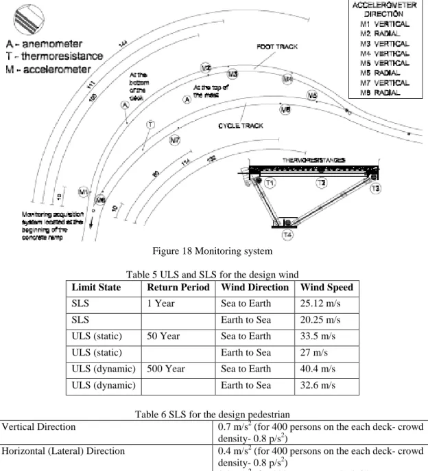
Structural identification and condition monitoring on site of the dynamic properties and stress states of “Ponte del mare” and S. Michele were performed too. These activities were much more complex for the first footbridge, indeed. In fact, the cable-stayed footbridge was characterized by two curved decks and provided with a vibration reduction system –viscous-fluid dampers- designed and installed to avoid premature aeroelastic instability and to control human-induced vibrations. The complex dynamic behaviour and the uncertainties related to numerical modelling led to a modal testing campaign of the bridge without and with dampers. Output-only ambient vibration tests, associated with low vibration levels, showed that the damping devices were basically inactive, owing to friction and connection slacks. In addition, for such low oscillation amplitudes dampers caused a stiffening effect that had not been envisaged earlier in the design process. Free decay tests, which were performed by released masses, did produce high vibration levels. In the latter tests, dampers showed a good absorption capacity and the damping doubled or even trebled on some of the vibration modes. In order to clarify these outcomes, modal quantities were calculated instantaneously, on the basis of time–frequency identification techniques. A thorough analysis of dynamic response signals revealed that the structure with dampers actually behaves like a threshold system: (i) for low vibration levels the dampers were still, so that they performed as constraints that stiffened the structure; (ii) for high vibration levels, the dampers became fully working and, as required at the design stage, they did not significantly affect main frequencies. With regard to monitoring activities, the whole monitoring system of Ponte del Mare was composed of 8 accelerometers, 4 thermo-resistances and 2 anemometers. Each of the anemometers provided two types of acquisition, that is, the wind speed and the wind direction, respectively. Three types of data were acquired during the period 17/12/2009-31/12/2010: i) temperature, wind speed and direction that were continuously monitored; ii) accelerations from all accelerometers, which were recorded at 5:58 p.m. every day for 82 seconds at 100 Hz; iii) trigger events: trigger was considered an extreme event when any of the eight accelerometers reached the limit of 0.4 m/s2 in vertical direction and 0.2 m/s2 in the horizontal direction. The maximum event happened at Christmas day (25/12/2009) with a large wind trigger that corresponded to a wind speed of 28.02 m/s. The majority of triggers occurred equally on Friday and Sunday. The accelerometer channels 4 & 7 were subject to the large number of triggers. Channel 4 was located near the end of the foot deck, while channel 7 was located in the middle of the cycle deck. The Fast Fourier Transform (FFT) of these data revealed information about the excitation frequencies. It was observed that frequencies below and near 1 Hz were well excited. This was due to the fact that wind typically excites frequencies below 1 Hz.
The corresponding structural identification and condition monitoring activities performed on the S. Michele footbridge highlighted no specific problems. In fact the footbridge was much more standard both in conceptual design and equipment. It was endowed with two twin tubular arches, far from locations of high wind and equipped with three classical tuned mass dampers for pedestrians. Nonetheless, it was very useful for fatigue model checks treated in Task 6.3.
WP3: Mechanical characterization of HSS and inelastic behaviour of HSS tubular members The main objectives of WP3 were: a) the mechanical characterization of HSS material including high-cycle fatigue and corrosion aspects; b) execution and evaluation of tests on tubular members characterized both by buckling and inelastic behaviour. The main results of this work package are summarized here. They are also widely reported in Section WP3 of Description of Activities and Discussion, in Appendix C and relevant Deliverables D3.1-D3.3 listed in the Amend. Technical Annex. With regard to the HSS base material, we chose TS590J2H quenched and tempered produced by Tenaris Dalmine, because they guaranteed a small production of 193.7 x 10 mm tubes – about 3.5 tons - and 355.6 x 12.5 mm tubes – about 1.5 tons – for this project. Nonetheless, we traced average yield strengths and tensile strengths of about 690 MPa and 766 MPa, respectively with elongations greater than 19 per cent. Though these properties satisfied quality control of Tenaris Dalmine, we understood that steel mills tend to use HSS for specific applications, e.g. tower cranes made of CHS with grade S690 or so, and therefore, also their adaptation to different grades can be limited. In any case, the aforementioned variability did not put at risk the under- over-matching ratios that we selected for welds. In fact, it was not that easy to conceive an intertwined experimental program comprising 63 specimens in total – see Figure 25 – and 88 tests for this WP – see Table 9 – used for: i) characterization tests on base material TS590J2H and welds with the inclusion of peening treatments; ii) testing on short and
long tubular members; iii) tests on welded and bolted connections with the inclusion of corrosion; NDT tests on realized specimens. Moreover also specimens made of S355J2 were included in the test program as specimens made of reference steel.
Fatigue characterizations of base material of tubes were performed by means of relevant S-N curves. ASTM E466-07 were followed
[8]
for axial fatigue tests considering a load ratio R=0.1. Fatigue limits for 2×10⁶ cycles corresponded to detail categories 432 MPa and 690 MPa for S355 and TS590, respectively. These values result to be more than satisfactory.The fracture toughness characterization was performed by means of the determination of a J-R curve for each base material. The test procedure followed the requirements of ASTM E1820
[9]
at ambient temperature. The corresponding energy for the onset of a stable crack growth resulted to be 620 kJ/m2 and 440 kJ/m2 for S355 and TS590, respectively. Moreover, inspection certificates indicate an average of 160 Joule for Charpy resilience V-notch (KCV) at -40 C much greater than J2 requirement.Several classes of electrodes, i.e. 32, 46, 55 and 79 were selected to reproduce the following weld types: Undermatching to grade S355; Overmatching to S355; Undermatching to TS590; Overmatching to TS590; Undermatching to TS590 and Overmatching to S355. The subcontractor Stahlbau Pichler does not usually employ Electrode class 55 and 79; as a result, we prepared with them Welding Procedure Specifications (WPS). In greater detail, they specified welding variables for our specific applications to assure repeatability by trained welders and welding operators, according to EN ISO 15609-1 [10]. The specimens were categorized for three types of non-destructive tests. The specimens under monotonic and low-cycle fatigue loading were chosen for visual inspection (VI) as well as for magnetic-particle (MT) inspection. The specimens under high-cycle fatigue loading were selected for ultrasonic testing (UT). With regard to weld specimens the subcontractor followed a defect acceptance criterion according to EN 1712 and EN 1291 for ultrasonic and magnetic particle methods, respectively. In general, pre-production welding tests allow for defects up to 3 mm. Obviously, we were much below this threshold and fatigue data of welded connections prove it.
Corrosion rate measurements and Slow Strain Rate Tests (SSRT) were performed on two different materials, i.e. TS590 and S355, in order to evaluate the susceptibility of materials towards stress corrosion cracking or hydrogen embrittlement. Uniform corrosion rates of base metals were measured in two different solutions, 1 wt% and 3.5 wt% NaCl, respectively, in order to simulate offshore and sea water environments, respectively. Tests were carried out at ambient temperature. The linear polarization resistance technique, based on the change in potential and record of the polarization was used to measure the corrosion rate. The electrochemical general corrosion rate measurements showed that steel TS590 had the same corrosion resistance or a slightly better value than the reference material S355. The SSRT-measurements showed that both TS590 and S355 were sensitive to stress corrosion cracking in the presence of cathodic polarisation.
In view of tests on tubular members, both geometrical imperfections and residual stresses were detected. Imperfections satisfied the product norm for seamless tubes, i.e. EN 10210-2 [11]; whilst longitudinal residual stresses on the outer surface ranged between + 74 MPa and – 60 MPa, bending components of longitudinal residual stresses were evaluated to be less than ± 10 MPa, and circumferential residual stresses were estimated to be + 93 MPa. Under the assumption of a triangular through thickness distribution the compressive residual stress of - 93 MPa was assumed for the inner surface. Several tests were conducted on 193.7 x 10 mm tubes under M, N and M-N action combinations. Because of its large slenderness, i.e. 75, with respect to the one of other tubes, e.g. 40 for 355 x 12 mm and 44 for 323.9 x 10 mm, some tests of 193.7 x 10 mm tubes prematurely ended. So other CHS were employed. Nonetheless, the entire test programme showed that the aforementioned tubes exhibited favourable characteristics at the section level, at the member level, adequate ductility and low strength degradation.
WP4: Performance of HSS welded and bolted connections
The main objectives of WP4 were: a) the mechanical characterization of welded HSS connections including high-cycle fatigue, corrosion aspects, weld characterization; b) execution and evaluation of
Also for this WP, we conceived an intertwined experimental program comprising 63 specimens in total – see see Figure 25 – and 130 tests for this WP – see Table 9 in this respect.
Fatigue characterizations were carried out on coupon specimens extracted from transverse butt weld connections of TS590J2H and S355J2 tubes, respectively. The study included the evaluation of the mismatching behaviour because welds were realized both in the overmatching and in the undermatching condition. The characterization was based on the determination of an entire S-N curve with a run-out of 2•106cycles with a load ratio R=0.1. Test results were fitted to a Δσ/2 - Log N linear curve in agreement with ASTM E739 standards [12], for fatigue data evaluation. Taking into account the reference value of 96 MPa for the reference steel grade S355, the overmatching condition exhibited a better fatigue performance than the undermatching condition; in fact we got 126 MPa for the overmatching case and 105 MPa for the undermatching case; see Table 17. Note that the detail category suggested by Eurocode 1993 Part 1-9 for this detail is 71. So both cases were favourable and undermatching is in general preferred because of less electrode strength and more ductility exhibited by welds.
Crack initiation was always located in the inner part of the tube, with a crack propagation always through the thickness. Two welded connections were treated by means of an ultrasonic process, i.e. peening, that consisted of cleaning the weld toe areas of the outer surface and the creation of a weld toe groove. The weld root in the tube inner surface was not treated by means of the ultrasonic equipment, both for costs and tool access reasons. As stated above, all fatigue failures initiated from the inner surface of the tube and progressed to the outer surface of the tube, i.e. the peened surface. Therefore, the peening treatment did not affect the fatigue performance of specimens.
The fracture toughness characterization was performed by means of the determination of a J-R curve for each welded connection. The test procedure followed the requirements of ASTM E1820
[9]
at ambient temperature. The corresponding energy for the onset of a stable crack growth resulted to be 440 kJ/m2 for TS590J2H base metal, 132 kJ/m2 for TS590 with an undermatching weld and 90 kJ/m2 for TS590 with an overmatching weld, respectively. The better condition of undermatching weldment is evident. In order to evaluate the susceptibility of materials to stress corrosion cracking or to hydrogen embrittlement, corrosion rate measurements and Slow Strain Rate Tests (SSRT) were performed on welds extracted from K- and X-joints and relevant Heat Affected Zones (HAZ) of two different materials, i.e. TS590J2H and S355J2, respectivley. Uniform corrosion rates of welds and materials were measured in two different solutions, i.e. 1 wt% and 3.5 wt% NaCl, respectively, in order to simulate offshore and sea water environments, respectively. Higher corrosion rates were achieved in 3.5 wt% NaCl compared to 1 wt% NaCl for all tested samples. Steel TS590 exhibited a lower corrosion rate than S355 in the most aggressive solution with 3.5 wt% NaCl, while it was slightly higher for the weld metal of TS590 in 1 wt% NaCl solution. From results, it was evident that cathodic polarisation, that it is intended to simulate cathodic protection drastically decreased the Reduction Area of all tested samples prepared, from base metal, welds and HAZ. The obtained results also indicated that the susceptibility to stress corrosion cracking increased in following order: base, HAZ and weld metal.Additional macroscopic examinations, hardness tests, and toughness tests were performed on butt welded connections, X joints and K joints. As a result, we concluded that the WPS used for welded connections were considered qualified according to EN 15614-1:2004 [13]; moreover, toughness requirements of 27J at - 20ºC in weldments were always satisfied.
Ten tests in agreement with the Amended Technical Annex were conducted on welded connections between 193.7 x 10 mm tubes and 355 x 12 mm tubes, under in-plane axial loading, in-plane bending and out-of-plane bending loading. Both monotonic and cyclic loadings were considered; R=0.1 for cyclic loading. Test results were able to characterize both strength capacity and ductility as well as low-cycle fatigue behaviour of examined welded joints. They performed quite well and failed with ductile foreseen chord face failure and punching shear mechanisms. See Eurocode 1993 Part 1-8 [14]. A similar testing program comprising six specimens - in agreement with the Amended Technical Annex - was conducted on bolted flange connections between 355 x 12 mm tubes subject to axial loading. Different combinations of plates – 20 and 15 mm thickness – and bolts – M27 and M20 – were considered in order to favour the activation of plastic failure Mechanism 1 and Mechanism 2 foreseen in Eurocode 1993 Part 1-8 [14]. Monotonic, cyclic and high-cycle fatigue loadings were considered; fatigue loading was considered with R=0.1. Test results were able to characterize both strength capacity and ductility as well as the high-cycle fatigue behaviour of bolted connections under exam. Their
behaviour was favourable both under monotonic loading in terms of ductility and under high-cycle fatigue loading when the hot spot stress approach is considered.
WP5: Numerical simulations of tubular connections; parametric study
The main objectives of WP5 were: a) to refine material parameter formula depending upon fast extreme loadings; b) response simulation both of welded and bolted connections under monotonic, cyclic and high-cycle fatigue loadings. The main results of this work package are summarized here. They are also widely reported in Section WP5 of Description of Activities and Discussion, in Appendix E and relevant Deliverables D5.1-D5.3 listed in the Amended Technical Annex.
With regard to the sensitivity of TS590J2H to strain rate, as done in previous WPs we also investigated the behaviour of reference grade S355J2 to these effects. In the case of impact or explosions this phenomenon must be necessarily considered. In the case of seismic action and at level of member, the rate of deformation can reach values of about 0.1, with increments of yield strength that can reach about 14 per cent. However in general, considering the uncertainty of seismic input and the effects of single members on the global behaviour on a structure, these effects reduce and wipe out. Conversely, the effect of strain rate on fracture toughness is much more significant, as several brittle failures occurred in members and joints close to welds during Northridge (1994) and Kobe (1995) earthquakes. In this context, we do not expect significant effects on well-designed Case studies, even if subject to typhoons or the like. Nonetheless, because of the character of this exploratory study, it was important to consider these effects on the grades to hand. As a result, low-cycle fatigue tests were carried out up to 10 Hz corresponding to a quite high strain rate of 1/s (= 10 per cent deformation * 10 Hz ). Experimental tests were conducted at room temperature and to clarify the dependence of mechanical behaviour, yield strength, ultimate tensile strength and elongation (fracture strain) were observed. Distributions of yield strength, ultimate tensile strength and elongation as a function of strain rates were plotted and fitted with typical power formula. With regard to TS590J2H, it was observed that yield strength increased, with increasing of strain rate; ultimate tensile strength also increased with the growth of strain rate; however, the elongation slightly decreased with increasing strain rate. These phenomena happened because yield strength and ultimate tensile strength increase because of strain-rate hardening. Moreover, increasing rate of yield strength is generally larger than that of ultimate tensile strength due to effect of thermal softening on the deformation. In addition, coefficients of the power formula fitted, indicate that TS590J2H mechanical properties are less sensitive to strain rate than those of S355J2 steel grade.
The simulation of welded X connections of tubular members subject to monotonic loadings was performed with the general-purpose finite element program ABAQUS/STANDARD, capable of modelling the detailed weld geometry, the weld material around braces, the loading sequence as well as nonlinearities. For critical regions of failure, the analysis considered nonlinear geometry through a large-strain description of deformable tubes, as well as inelastic material behaviour, accounted for through an appropriate J2 flow (von Mises) large-strain plasticity model. We recall that the weldment profile in connections of CHS members was made according to EN 1993 Part 1-8 [14]. Nonetheless, due to the insufficient information, weld profiles for CHS X and K joints were also taken by the American Welding Society (AWS) code
[15]
. Numerical models of connections subject to axial loading, in-plane bending and out-of-plane bending were compared to experimental results. Therefore, chord face failure and punching shear failure which are ductile mechanisms favoured by EN 1993 Part 1-8 were checked. Apart from predicting the load-displacement behaviour of the joint, an important target of the numerical investigation was the calculation of cyclic strain variations in critical weld locations and their comparison with experimental measurements. Furthermore, test results and numerical simulations indicated effects of chord-to-brace diameter ratio, chord diameter-to-thickness ratio and chord-to-brace thickness ratio to the behaviour of examined connections.Numerical simulations on bolted flange connections were performed by means of the FE program LAGAMINE developed at University of Liege. This program permits the analysis of mechanical, thermal and dynamic problems with large deformation taking in to account geometrical and material non-linearities. Due to symmetry of circular flange joints, only a 1/8 of a half of specimen model was
were taken into account by means of the Agerskov’s model. Also in this case, FE models were able to capture both monotonic and low-cycle fatigue response of specimens. In the case of monotonic loading, observed plastic failure mechanisms corresponded to the designed ones. Moreover, bolted connections exhibited a favourable behaviour in terms of strength and ductility.
High-cycle fatigue modelling both of welded and bolted connections required a deeper investigation. First of all, differently from Eurocode 1993 part 1-9 [16] that merges geometric stresses with hot spot stresses we clearly distinguished these stresses: i) the geometric stress is the maximum principal stress in the parent material that includes concentrated load effects, misalignments and macro-geometric effects in the connection, but it disregard the presence of the weld itself in a detail; ii) the hot spot stress is the maximum principal stress in the parent material that includes concentrated load effects, misalignments and macro-geometric effects in the connection, and includes the presence of the weld itself. Eurocode 1993 part 1-9 [16] tries to estimate hot spot stresses by means of the magnification factor k1 for welded connections and the Stress Concentration Factor (SCF) kf for bolted connections, to
take account of the local stress magnification in relation to detail geometry not included in the reference S-N curves. Because values of k1 appear quite small with respect to values provided in CIDECT reports
[17], and because SCF values are hidden in the S-N curves or not provided in the Eurocode 1993 part 1-9 [16], it was decided to estimate these values either experimentally or numerically by means of strain gauges or refined finite element meshes around welds. In greater details, several extrapolation methods were considered to estimate the hot spot stress at weld toe. With regard to welded connections of X joints, the method suggested by Romeijn [18] reported in the CIDECT report [17], was considered. Conversely wit reference to bolted flange joints, the hot spot stress in plates at weld toes was estimated by : i) the Linear Surface Extrapolation method (LSE) [19]; ii) the Through Thickness at the Weld Toe method (TTWT) [20]; iii) the structural stress from the distance method based on the Dong’s method [21]. The LSE method is a simplified technique that can be used both for experimental- and numerical-based approaches. Conversely, the main idea of TTWT and Dong’s method are to find a structural stresses through a plate thickness that are in equilibrium with the notch stress –or hot spot stress at the weld toe-. Comparisons between experiments and simulations pointed out that the LSE method is not recommended for bolted connections; as a result, hot spot stresses provided either by TTWT or Dong’s were used.
WP6: Numerical simulations of tubular members and structures; parametric study
The main objectives of WP6 were: a) to analyse and determine S-N data for welded/bolted connections with CHS; b) to simulate the behaviour of tubular members; c) to simulate some peculiar aspects of case studies. The main results of this work package are summarized here. They are also widely reported in Section WP6 of Description of Activities and Discussion, in Appendix F and relevant Deliverables D6.1-D6.3 listed in the Amended Technical Annex.
Low-cycle fatigue S-N curves of welded tubular connections were based on the hot-spot methodology described in WP5. For instance for out-of-plane bending low-cycle fatigue tests of X connections carried out in Task 4.2, the Strain Concentration Factor (SNCF) numerically estimated was equal to 7.18, higher than the experimentally evaluated value. According to CIDECT guidelines [17], the corresponding Stress Concentration Factor (SCF) for the connection under exam was equal to 9.82, whereas the numerical model entailed a SCF value equal to 6.16 using a linear extrapolation and 8.19 using a quadratic extrapolation suggested by Romeijn [18]. The above differences are attributed to the sensitivity of the strain/stress field near the weld toe owing to local conditions (notch effect). Because structural components were loaded with repeated excursions well into the inelastic range of material behaviour, we extended high-cycle fatigue curves to low-cycle regime by a method proposed by Ballio et al. [22]; an equivalent elastic stress range was introduced and a linear extension of the S-N curves in the log-log scale was made. Using this approach, the experimental number of cycles for the X-joints under consideration both for out-of-plane bending and in-plane bending endowed with overmatching and undermatching welds were beyond S-N data suggested by CIDECT manual [17]. Moreover and due to presence of monotonic tests, a cut-off criterion for very low cycle numbers is suggested.
A large set of high cycle fatigue data were produced on tensile sample coupons machined from girth welded CHS connections. These tests were performed in Task 4.1 both with Overmatching where TS590J2H elements were butt welded using a G79 consumable, and with Undermatching (U) where TS590J2H elements were butt welded using a G55 consumable. Values of stress range corresponding to 2 million of cycles were calculated with a 75% confidence level and a survival probability of 95% as recommended in Eurocode 1993 Part 1-9 [16]. Both Overmatching and Undermatching specimens
satisfy the Detail Category 71 of Detail 3 of Table 8.6 – or Detail 13 of Table 8.3 - and Overmatched weldments provide a better fatigue performance. With regard to bolted connections two high-cycle fatigue tests were performed on specimens with flange thickness of 15 and 20 mm, respectively. Cracks happened always at the weld toe of tubes, and only for the ticker flange a bolt cracked too. FE simulations and the evaluation of structural stresses based on the Dong’s method, allow hot spot stresses to be correctly evaluated in tubes, flanges and bolts; in this case, detail categories offered by Eurocode 1993 Part 1-9 are conservative. In other cases where stresses in the parent material or in a weld adjacent to a potential crack location are calculated in accordance with elastic theory excluding all stress concentration effects, i.e. with the nominal stress, it may lead to unsafe results; hence, components are necessarily overdesigned when using the nominal stress approach.
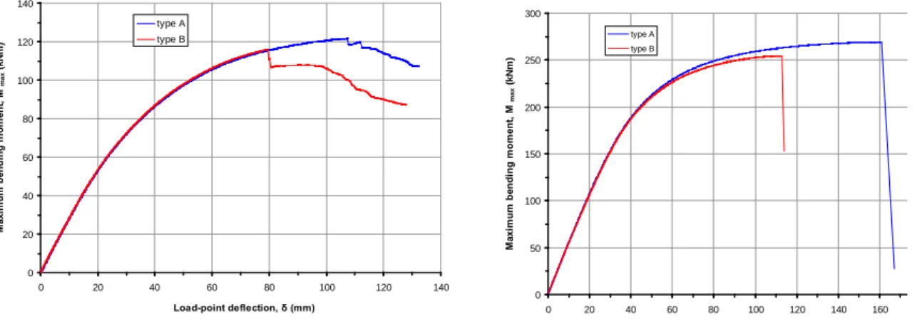
FE simulations of beam-column specimens tested in WP3 were performed with nonlinear finite element models by ABAQUS/STANDARD software. The tube cross-section was endowed with nominal diameter and thickness equal to 193.7 mm and 10 mm respectively. The FE models employed shell elements, which were capable of describing rigorously the behaviour of CHS members, and accounted for nonlinear deformation and plasticity of the steel, through a Linear Kinematic Hardening (LKH) model. A parametric study on beam-columns with the above cross-sectional dimensions was conducted. Moreover, both because of slenderness problems of the aforementioned section and of the need to obtain quite complete M-N diagrams, also members with cross-section ∅355.6/12.5 and ∅323.9/10 were simulated too. Ticker specimens failed after several loading cycles due to fracture near the end connection; thinner specimens sustained a few cycles until local buckling took place. As a result, detailed numerical models were developed using 8-node solid elements (C3D8H) based on a linear-hybrid formulation. Also the stiff steel stubs located between specimens and machine hinges were simulated. A key modelling issue was hardening of the cyclic plasticity model; so cyclic plasticity phenomena and the change of the cross-sectional geometry –ovalization- were captured. In this respect, two von-Mises plasticity models were used, i.e. the LKH model and the more advanced Tseng – Lee (TL) model, which adopts the “bounding surface” concept; it was implemented into ABAQUS through a UMAT user-subroutine. Relevant comparisons between experimental and numerical data are provided in Section WP6 of Description of Activities and Discussion, in Appendix F and relevant Deliverables.
Two reasons were behind simulations of some case studies: i) to analyse the performance of “Ponte del Mare” and discover possible overstressing due to various loading conditions; ii) to investigate possible high-cycle fatigue problems for the design of footbridges, as underlined in the RFS HIVOSS project [2]. With regard to the performance of “Ponte del mare”, to get a robust FE model capable of simulating the actual behaviour of the footbridge, the initial FE model was updated on the basis of experimental data. The sensitivity-based model updating techniques and Powell’s Dog-Leg method based on the Trust-Region optimisation approach were used. The sensitivity matrix was calculated and nine most sensitive parameters were selected. In order to check its applicability, the updated FE model was used to reproduce the acceleration response under the actual wind recorded on 25/12/2009; then several simulation were carried out for ultimate limit state conditions: the footbridge behaviour resulted to be satisfactory. With reference to high-cycle fatigue limit states, fatigue checks on three different typologies of footbridges were performed: on Ponte del Mare, S. Michele and Nomi-Calliano footbridges. Severe pedestrian loadings were taken from Technical Guide Setrà [23], where it was possible to select pedestrian load models and a methodology for vibration analysis due to human walking. For high-cycle fatigue checks, Eurocode 1993 Part 1-9 was chosen. FE analyses combined with reasonable assumptions and safety checks clearly indicated that none of the footbridge typology considered was prone to fatigue problems owing to pedestrian loading.
WP7: Development of design guidelines and recommendations for high strength tubular structures
The main objectives of WP7 were: a) to develop design guidelines and recommendations for HSS steel for onshore structures under extreme loadings, for welded connections, for bolted connections and for tubular structures; b) to develop Bayesian life-cycle models for maintenance and durability. The main
With regard to HSS steel for onshore structures given the fact that mechanical characteristics of TS590J2H are quite good, only some aspects were deepened. With reference to transverse butt welds of sample coupons extracted by CHS subject to fatigue and considering a 75 per cent confidence level with survival probability of 95 per cent, typical reliability values used in Eurocode 1993 part 1-9 [16], details categories with nominal stresses are 71 MPa and 47 MPa for Overmatching and Undermatching weldments, respectively. Because the Detail Category suggested by Eurocode 1993 Part 1-9 is 71 MPa, overmatched welds provide better fatigue performance. Nonetheless, we have to note that only nominal stresses and not hot spot stresses were considered here. Moreover, it must be noted that Eurocode 1993 part 1-9 merges hot spot stresses with geometrical stresses and tends to underestimate Stress Concentration Factors. The corrosion resistance of TS590J2H is of essential importance in offshore applications. It was also shown that TS590J2H is sensitive to stress corrosion cracking in presence of cathodic polarisation. This susceptibility is higher for the weld metal than the base metal. The heat affected zone that arises during welding is also more susceptible to stress corrosion cracking than base metal but lower than weld metal. Nonetheless, its performance against corrosion is slightly better than S355J2 steel grade.
In welded tubular connections, failure usually occurs in the form of cracks at a discontinuity or stress raiser, associated with a microscopic defect at the weld toe. As a result, cracks under monotonic, low-cycle or high-cycle fatigue loading initiate at these locations irrespective of steel grade. Eurocode 1993 Part 1-8, Design Guides No. 1 [24] and 8 [25] present typical weld details at the main locations of welded tubular connections made of CHS. Nonetheless, additional information on weld details were needed and taken from the AWS Welding Code
[26]
. Weld start/stop positions for non-continuous welds should not be located at points of high stress concentration -crown and saddle points-, since these can cause themselves stress concentrations. Higher steel grades can be used to improve connections static strength, but they do not necessarily improve deformation capacity or high-cycle fatigue strength. Design provisions of EN 1993-1-8 (2002) [27] are identical to those proposed by Wardenier et al. [28] for ultimate resistance, and they are used for predicting the joint capacity under axial load or bending loading. Results of the present study have shown that static strength equations of the aforementioned specifications are adequate and that strength reduction factor equal to 0.8 for the HSS under exam with overmatching weldments suggested by EN 1993-1-12 (2009) [29] is unnecessary. With regard to high-cycle fatigue, Eurocode 1993 Part 1-9 [16] provisions for welded tubular joints adopt the “classification of details” method, which is not applicable to the majority of tubular X-joints. Therefore, hot spot stresses and stress concentration factors must be quantified. Various methods of improving the fatigue resistance of welded connections are available. Mechanical peening mainly introduces compression stresses in the weld toe to reduce tensile stresses effects. The peening treatment should be carried out in the inner part of tubes.With regard to bolted connections subject to monotonic loadings, several methods were considered in order to estimate their plastic failure capacity. Predictions were always on the safe side and differences between predictions and experiments ranged between 4% and 40%. Predictions provided by Eurocode 1993 Part 1-8 were the most accurate ones. As far as high-cycle fatigue behaviour is concerned, it was shown that the use of Detail Category 11 of Table 8.5 in Eurocode 1993, part 1-9 overestimates fatigue strength, and therefore is unsafe. Nonetheless, the use of the hot-spot stress concept estimated through finite element analyses via the Dong’s method [21] allowed a safe prediction of the fatigue strength to be made, via a Detail Category 100. Moreover, stress concentration factors were estimated too. Initial deformation of flanges owing to heat effects during welding significantly influence the stress range both on tubes and flanges. Therefore in view of an economic design, initial deformations should be taken into account in FE models.
CHS tubes with nominal dimensions of 193.7mm in diameter and of 10mm in thickness were analysed. Considering actual mechanical properties of members -fy = 694 MPa; D/t = 19.4- the relevant cross
section was classified as Class 2 in accordance with EN 1993-1-1 [30], whilst considering its nominal strength fy = 590 MPa a Class 1 section is obtained. Full-scale tests were performed with two different
column lengths: i) short length -member slenderness
28.4-
relevant to its cross sectional behaviour; ii) long length -member slenderness 74.6- relevant to member behaviour. Experimental data were compared with Eurocode 3 predictions in the N-M interaction diagram using both Method 1 -m1- and Method 2 -m2-. Experimental results are on the safe side of the interaction diagram indicating thatrecommended design formulae can be consistently extended to HSS members for the slenderness range investigated.
The Ponte del mare of Pescara redesigned with tubular sections offered us two possibilities for checks: on one hand both with identification and numerical data, we had the possibility to check and employ several indications provided by Eurocode 1993 Part 2 for steel decks and Eurocode 1991 Part 1-4 and Eurocode 1993 Part 3-1 for masts of Ponte del Mare with reference to along-wind and vortex-shedding wind loadings; on the other hand, we estimated the safety of footbridge decks by means of the calculation of the reliability index β -or the probability of failure Pf-, followed by a Bayesian updating
technique. It can use both prior information and new inspection information to account for the relative uncertainty associated with each variable. In greater detail, assigned Weibull density probability functions for pedestrian loads and for wind loads -for corrosion rates of members Gaussian distributions were used-, we simulated the progressive reduction of painting effects and the concurrent increase of corrosion for a reference life time of 50 years. The probabilistic evaluation of the safety margin and reliability of the deck of the footbridge was conducted using non-linear simulations based on Monte Carlo Sampling (MCS). Although MCS is straightforward to apply, as it only requires repetitive executions of deterministic simulations, typically a large number of executions are needed, because solution statistics converge relatively slowly – for example the mean value typically converges as 1
√𝐾,
where K is the number of realizations. So we have applied the Latin hypercube sampling to accelerate convergence of the brute-force MCS. Several limit states in terms of maximum strength, maximum deflection, and maximum deck rotations were considered. As a result, and with reference to the maximum deck rotation, the value of β crossed the limiting value at about 23 years and 33 years for the case without and with wind, respectively. This showed also that wind acted in the way to increase the reliability of the footbridge structure, owing to lifting effects. Moreover, the decision should be based on the critical case, i.e. the one without wind. Therefore, the repair and/or retrofit plan of footbridge decks should be activated by 23 years of lifetime in order to increase its reliability index.
WP8: Project coordination
The main objectives of WP8 were: a) to establish an efficient management process; b) to define standard protocols, c) to carry out the SWOT evaluation; d) the activity monitoring of the project. The main results of this work package are summarized here. They are also widely reported in Section WP8 of Description of Activities and Discussion, in Appendix H and relevant Deliverables D8.1 and D8.2 listed in the Amended Technical Annex. In greater detail, all coordination meetings were regularly carried out, the FTP server directory was created by UNILG and continuous exchanges favoured objectives and relevant project outcomes. Moreover, common standard testing protocols were very effective for assuring quality of test results. The evaluation of the project in terms of Strength, Weakness, Opportunity and Threat allowed a global evaluation of the research project both in terms of activity coordination and work effectiveness of each research unit. Finally, intermediate reports and set of deliverables enabled internal and external monitoring of the project advances, and of the degree of fulfillment of objectives set for various phases.
Conclusions and main results
New steel production processes have led to a remarkable improvement in steel products within the last few years, and now they allow steels to be produced according to desired mechanical and chemical properties. High Strength Steel (HSS) or High Performance Steel is the designation given to this new generation of steels that offer higher performance, especially in the case of tubular members produced for structural applications, not only in terms of strength but also toughness, weldability, cold formability and corrosion resistance, compared to the traditionally used mild steel grades. The development of HSS goes with today’s increased demand for slender lightweight structures, as for instance in footbridge and bridge design. However, on the structural engineering side there is a need for knowledge of these new steel grades combined to proper conceptual designs. Nonetheless quite often,
two specific structural types for which tubes could be suitable for architectural and aesthetic reasons: i) slender foot- and cycle-bridges; ii) arches and truss elements of railway bridges, under extreme natural and anthropic repeated loadings, some of which were measured in situ. Necessary tools were the use of tests at the material, member and connection level, in structural labs and both identification and monitoring in situ, of finite element-based tools, of reliability assessment of a realistic case study. The project reported relevant behaviour of members, welded and bolted connections under monotonic, low-cycle fatigue and high-cycle fatigue loading, weights reduction and reliability analysis results. List of deliverables of the project:
Information about deliverables is listed in Table 1.
Table 1 List of deliverables Deliverables and
Milestones
Due date Finalisation date
Form Location Partner- in-charge D1 (D1.1, D1.2, D1.3, D1.4) December 2008 March 2010 Mid-term report CIRCA KIMAB,ISQ, UNITN,UNITH D2 (D2.1, D2.2) December 2008 March 2010 Mid-term report CIRCA UNITN,UNILG, UNITH D3 (D3.1) March 2010 September 2011 Six-monthly report CIRCA KIMAB,ISQ, ITMA D3 (D3.2, D3.3) March 2010 March 2012 Deliverable
report CIRCA CSM D4 (D4.3) September 2009 March 2011 Six-monthly report
CIRCA UNITH,ISQ, ITMA D4 (D4.1, D4.4) March 2010 September 2011 Six-monthly report CIRCA ISQ,KIMAB, ITMA,UNILG D4 (D4.2) March 2010 March 2012 Deliverable
report CIRCA UNITH D5 (D5.1) June 2010 September 2011 Six-monthly report CIRCA UNITH,UNILG D5 (D5.2) June 2010 March 2012 Deliverable
report CIRCA UNITH D5 (D5.3) June 2010 September 2011 Six-monthly report CIRCA UNILG D6 (D6.1, D6.2) December 2010 March 2012 Deliverable report CIRCA CSM,UNITH, UNITN,UNILG D6 ( D6.3) December 2010 September 2011 Six-monthly report CIRCA UNITN D7 (D7.1, D7.2, D7.3) December 2011 March 2012 Deliverable report CIRCA ITMA,KIMAB, CSM,ISQ,UNILG, UNTH,UNITN D8 (D8.1, D8.2) December 2009 March 2010 Mid-term report CIRCA UNITN
Scientific and technical description of the results
In the following main aims, activities and results of the project are described. Additional details are reported in the enclosed appendices.
Objectives of the project
High strength steel (HSS) has been available for many years. However, its use in onshore engineering is quite restrictive. One reason is that structural codes and Eurocodes have covered steels with yield strength up to 460MPa; the other reason is higher costs than regular steel. Nonetheless very recently, there has been a growing trend for the use of high strength steel in tubular structures thanks to Eurocode 3 Part 1-12 (2006) that has extended its scope to steel grades up to S690/S700MC.
The HITUBES project intends to develop performance-based designs and assessment procedures to make full use of HSS tubes up to S700MC for structures subjected also to extreme repeated loads; in fact Eurocode 3 Part 1-12 imposes many limitations at the material, structural and design level. The
ambitious targets are to increase the performance of tubular structures, reduce weights, construction and operating costs.
In particular in order to achieve the above mentioned goal the work was mainly focussed on: → literature survey and selection of case studies;
→ selection of FE codes, simulations and investigations on case studies; → structural identification and monitoring of footbridges;
→ tests on HSS materials and welds also considering post-weld treatment; → tests on HSS tubular members and bolted and welded connections; → simulations on HSS tubular members and bolted and welded connections; → simulation on footbridges and fatigue check;
→ development of design guidelines;
→ standard protocols, SWOT analysis and monitoring of project activities. Comparison of initially planned activities and work accomplished
The initial Technical Annex 1 was amended due to the difficulty in realizing the wind turbines of varying tubular sections. The aims and objectives of the project have been accomplished without any substantial changes from that mentioned in the Amended Technical Annex 1. A considerable number of tests have been performed allowing to cover the main aims of the project.
Some modifications to the testing program reported in the Technical Annex were agreed during the project, in Table 2 a comparison between the Technical Annex and actual testing program is reported:
Table 2 Testing program changes with respect to the Technical Annex
Technical Annex Actual testing program
Task 3.2 3 cyclic tests under axial and bending 5 full scale cyclic tests under bending (symmetric and asymmetric)
Task 3.3 9 cyclic tests under axial and bending 10 full scale monotonic tests under axial and bending
Description of activities and discussion
WP1: Review on test data and design procedures on tubular members and connections and Bayesian approaches for probabilistic risk assessment
Objectives of the WP1 (Tasks 1.1, 1.2 & 1.3) Main aims of this work package were as follows:
- Collection and evaluation of test data and design procedures on tubular members relevant to the investigated structures
- Collection and evaluation of test data and design procedures on tubular joints under fatigue loading
- Corrosion aspects of HSS material
- Collection of literature on foot/cycle/rail/road bridges made of HSS and/or tubular sections - Evaluation of Bayesian approaches for probabilistic reliability assessment
- Choice of output-only identification techniques Activities and results obtained
Task 1.1: Collection and evaluation of experimental test data on tubular members and joints relevant to the investigated structures under extreme repeated loadings
The classification of cross sections is closely related to the ductility of the material, the ductility of the element section and local buckling phenomena. An important problem of HSS section, owing to the high yield strength, consists of respecting the classification limits imposed by Eurocode 3-1-1. The classification of cross sections is function of the factor
Test data and design procedures on tubular members and joints under monotonic loading
y
f 235 =
ε , so that HSS is penalized. In addition the classification is function of the D/t ratio that is often high with use of HSS sections. Several studies
are given in EN 1993-1-1 [33], CIDECT No. 2 [34] and API PR 2A – LRFD [35]. Moreover, the design procedures on tubular joints under monotonic loading are given in EN 1993-1-8, CIDECT No.1 [24] and API PR 2A – LRFD [35]. Details can be found in Appendix A.
Task 1.2: Evaluation of design procedures and techniques for welded/bolted HSS members and joints for low-cycle and high-cycle fatigue
There are two methods for fatigue design of structural details: the classification method and the hot spot stress method. The design procedures on tubular joints under fatigue are given in EN 1993-1-9 [16], CIDECT No.8 [17] and API PR 2A – LRFD [35]. Details can be found in Appendix A.
Test data and design procedures on tubular members and joints under fatigue
The literature survey showed that there are a lot of corrosion and stress corrosion cracking studies related to the oil and gas industry where the pipelines are made of medium or high strength steels. However, there is limited information of the long-term use of high strength steels in sea water and under severe conditions where the structures are subjected.
Corrosion aspects of HSS material
The corrosion forms that has to be considered in offshore environments are; pitting and crevice corrosion and stress corrosion cracking (SCC). Similar to SCC is another common failure, the hydrogen related stress corrosion cracking, sometime also called hydrogen embrittlement. There are three conditions that are important for SCC and hydrogen embrittlement to occur; the material should be susceptible to these types of corrosion, the environment should be corrosive e.g. hydrogen containing environment, and there should be a sufficient stress intensity. In offshore environments, chloride, CO2
and H2S play an important role as well as hydrogen formed at cathodic protection for the corrosion
process. Another important source of hydrogen is from welding if not sufficient care is taken.
Furthermore, the literature review showed that the materials resistance to hydrogen embrittlement depends strongly on the microstructure. The susceptibility for hydrogen embrittlement is ranked in the order: tempered martensitic < tempered bainite < spheroid ferrite and pearlite < coarse ferrite and pearlite. In some papers it is declared that the strength or hardness of specific steel usually can give a first indication of its hydrogen embrittlement susceptibility. However, in most cases all the parameters as environment, microstructure and the level of strength have a great influence of appearance of hydrogen embrittlement. It is also stated that it is of great importance that each steel quality should be considered individually and should be subjected for testing before being accepted for use, especially in critical conditions. Recommendations, given in the literature, to control the cracking are: (i) emphasis on material selection, for example by use of slow strain rate testing (SSRT); (ii) high control over welding procedures; (iii) avoidance of anaerobic condition (e.g. hydrogen evolution corrosion in the absence of oxygen); and (iv) limiting the potentials of cathodic protection to minimize the generation of hydrogen.
Task 1.3: Collection of literature on foot-cycle bridges. Evaluation of Bayesian approaches for time dependent formulations in order to perform probabilistic risk assessment and carry out fatigue reliability. Choice of output-only identification techniques.
Collection of literature on
bridges-Foot/cycle/rail/road bridges made of HSS and/or tubular sections:
The collected bridges are organized with relevant information as follows:
i) Bridges made of tubular sections - Forth Rail Bridge in Scotland
- Eads Bridge in St Louis (road and railway) USA
- Tempe town lake light rail bridge Tempe, Arizona, USA
- St. Kilian viaduct, Germany [36]: tubular trusses in deck, see
Figure 1
a - St. Luitpold Bridge, Bamberg, Germany [36]: tubular arches, seeFigure 1
b - Weil am Rhein footbridge, Germany, [36]: tubular arches- Dattwill Bridge, Swiss [36]: tubular trusses in deck - Nesenbachtal, Stuttgart, Germany [36]: tubular trusses - Landegem railway bridge, Belgium: RHS arches
- Ponte del Mare foot-cycle-bridge, Pescara, Italy: tubular mast - San-Michele footbridge, Trento, Italy: tubular arch with S460 - Nomi footbridge, Trento, Italy: tilted RHS arch
Figure 1 a) St. Kilian viaduct, Germany b) Luitpold bridge, Germany ii) Bridges used high strength steel sections
- Verrieres Viaduct, France [37]: S460 in deck
- Prince Claus Bridge, Holland [37]: S460 ML in pylon - Ilverich Bridge, Germany [37]: S460 TM in pylon
- Rion Antirion, Greece [37]: S460 TM in composite girder and pylon - Millau Viaduct, France [37]: 40% steel used S460 TM in deck and pylon - Jassanas-Riottier Bridge [37]: 20% steel used S460 TM in deck
- Garrigues viaduct [37]: S460 in deck
- Messina Bridge [38]: S420 and S460 at some length of deck, pylon - Bayerstrasse, Munich, Germany [36]: S690 in tubular arches, see Figure 2
Figure 2 Bayerstrasse, Munich, Germany iii) Bridges experienced extreme events
- Golden Gate Bridge, San Francisco: 112 km/hr wind in 1951
- London Millennium Bridge [39]: 7 cm deck vibration amplitude due to pedestrians in 2001 - Tsing Ma Bridge [40]: 28 m/s wind typhoon

![Figure 4 Original and updated reliability indices using Bayesian theory, after [45]](https://thumb-eu.123doks.com/thumbv2/123doknet/6625337.180509/22.892.229.668.379.604/figure-original-updated-reliability-indices-using-bayesian-theory.webp)