This is an author-deposited version published in: https://sam.ensam.eu Handle ID: .http://hdl.handle.net/10985/6956
To cite this version :
Fabrice LOCMENT, Eric SEMAIL, Xavier KESTELYN - Vectorial Approach Based Control of a Seven-Phase Axial Flux Machine Designed for Fault Operation - IEEE Transactions on Industrial Electronics - Vol. 55, n°10, p.3682-3691 - 2008
Any correspondence concerning this service should be sent to the repository Administrator : archiveouverte@ensam.eu
Abstract—This paper deals with easy to implement control
strategies when a seven-phase Axial Flux Permanent Magnet machine (AFPM) supplied by a seven-leg Voltage Source Inverter (VSI) is in fault operation mode. Using a vectorial multi-machine description, a seven-phase multi-machine presenting a heightened ability to be controlled with one or two open-circuited phases has been designed. The machine is first presented and experimental results are provided when one or two phases are open-circuited. Based on a vectorial approach, new current references are calculated to avoid high torque ripples.
Index Terms — fault tolerance, multiphase synchronous
machine, reliability, torque ripple.
I. INTRODUCTION
ULTIPHASE machines find their applications in variable speed drives [1]. One of their drawbacks is that they apparently require a higher number of switching devices than three-phase machines. Nevertheless, in high power applications such as electrical ships [2] or low voltage/high current applications such as on-board traction systems [3]-[4], this drawback is not so obvious: the use of high current devices needs high heat dissipation capabilities especially with high frequencies. In these cases parallel converters or parallel/series device associations are often used instead of two-level VSI.
Moreover, when a high degree of reliability is required, such as in aircraft [5] or in marine applications [6], multiphase drives [7] should be considered as an alternative to three-phase multi-level converter drives, whose reconfiguration in safety mode presents a certain number of difficulties.
Contrary to three-phase wye-connected machines, the loss of one phase is not critical for seven-phase machines. However, torque ripples appear when classic vector control of the machine [6]-[8] is implemented. These ripples come from the interaction between the non-symmetrical system of currents and the symmetrical system of electromotive forces (EMF).
Manuscript received February 28, 2007. Accepted for publication April 17, 2008.
Copyright © 2007 IEEE. Personal use of this material is permitted. However, permission to use this material for any other purposes must be obtained from the IEEE by sending a request to pubs-permissions@ieee.org
F. Locment, E. Semail and X. Kestelyn are with L2EP ENSAM, 8 Bd Louis XIV, 59046 Lille Cedex, France, URL: http://l2ep.univ-lille1.fr/.
In the case of multiphase induction machines, new current references are determined in order to set a smoother torque under fault condition [9]-[10]. In both papers, only the first harmonic of current is considered when establishing an expression for the torque. It is thus assumed that multiphase induction machines present fewer constraints than the synchronous machines with non-sinusoidal EMF. Moreover, this assumption makes possible the torque to be expressed in a relatively simple manner. Experimental results, obtained in [10] regarding current control, show that practical implementation is possible. Nevertheless, since the expression of the torque relies on the assumption that only the first harmonic is taken into account, a real measurement of the torque should be preferable to prove that the torque ripples are in fact low. Furthermore, as no information is given on the type of used current controllers and on the PWM frequency, it is difficult to determine the modifications that must be made to the control algorithm implemented for the normal operation.
In [11], a five-phase synchronous machine with concentrated windings and non-sinusoidal EMF is considered in fault mode. In this case, it is said that, with the proposed method, torque pulsation can appear. New current references are determined to get a desired magnetomotive force distribution. Corresponding currents are obtained using hysteresis controllers in the stator reference frame of a synchronous machine. Results on current control are good but there is a lack of torque measurements, especially interesting considering that the second harmonic of torque ripple depends on the third EMF harmonic. Moreover, in the case of hysteresis controls, the switching frequency is not constant which harms electromagnetic compatibility. Consequently hysteresis controllers are seldom used for high power industrial drives.
In [12], analytical predeterminations of the torques for a five-phase synchronous machine taking into account the third harmonic are carried out with one and two open-circuited phase. The currents in the stator reference frame are determined in order to attenuate the second harmonic of the torque ripples. Obtained torque measurements show that the ripples are in fact weak. Nevertheless, insufficient information about the type of the current controllers is given to be able to determine both the necessary modifications for implementation in fault mode configuration and the ability of
F. Locment, E. Semail, Member, IEEE and X. Kestelyn, Member, IEEE
Vectorial Approach Based Control of a
Seven-Phase Axial Flux Machine Designed for Fault
Operation
the controllers to be used in high power applications.
In [8] for a five-phase PM machine, a new model of the drive is defined for each different fault operation case. Using a specific transformation that leads to constant references in steady state, the current control is carried out in a synchronous frame with Proportional Integral (PI) controllers. The steady state errors are then equal to zero. However, in order to use this technique it is necessary to build several models of the drive, one for each fault case, and to switch between several control modes.
In this paper, the machine is assumed to have no internal faults. Thus, the same machine model and consequently the same control structure with PI current controllers in dq frames are maintained for both operation modes. The same kind of efficient control structure as presented in [8] is implemented. The PWM frequency is fixed and PI controllers are used, but the model remains unchanged. Moreover, torque measurements confirm that it is possible, with a seven-phase machine, to drastically reduce the torque ripples in fault mode, using the same control structure as in the normal mode.
In section II, from the suggested model, constraints on both the machine and the control algorithm are deduced. In section III, a seven-phase NN TORUS machine designed using analytical and 3D-Finite Element Methods [13]-[14] is presented. In section IV, experimental results are provided from the implemented control algorithm when operating normally and when one or two phases are open-circuited. Using the same simple control structure as the one used in normal operation, it is shown that it is possible for torque ripples to be weak in fault operation if two current references are adapted. The corresponding copper losses are evaluated in order to deduce the reduction of the torque reference necessary to maintain the same thermal constraint.
II. VECTORIAL MULTI-MACHINECHARACTERIZATION The control structure is deduced from a multi-machine multi-converter model of a seven-phase machine supplied by a leg VSI [13]. Using this modelling method, the seven-phase machine can be considered as a set of three fictitious machines. Mathematically, this approach is close to the multi-reference frame approach [15] but highlights the design constraints and the physical couplings which have to be taken into account by the control algorithm. The mathematical basis of the two approaches, introduced for six-phase machines [16], is the same: the existence of orthogonal subspaces associated with the eigenvalues of the stator inductance matrix. The multimachine approach is a generalization of the concept of equivalent two-phase machines introduced in [17] for multiphase machines, but taking into account all the spatial and time harmonics and not only the first one.
Using this approach the main characteristic properties of multiphase machines are summarized in this section. The particularity of the seven-phase machine used to implement the proposed control is highlighted.
Under the assumptions of no saturation, no eddy currents,
no reluctance effects and regularity of the design, the model of a seven-phase machine can be described by equations (1) and (2): d i v Ri e dt Λ⎛ ⎞ = + ⎜ ⎟+ ⎝ ⎠ G G G G (1) e . i T Ω = G G (2) with:
− vG, iG and eG the seven-dimensional stator voltage, current and EMF vectors respectively.
− R the stator resistance and Λ a linear relation described by a 7-by-7 stator inductance matrix. − T the electromagnetic torque and Ω the
mechanical speed.
Using a Concordia-type orthonormal transformation
[ ]
C7 , as shown in (3), which diagonalizes the stator inductance matrix, (1) can be broken down into a set of one one-dimensional and three two-one-dimensional independent equations (4). [ ]=7 1 1 0 1 0 1 0 2 1 2 2 4 4 6 6cos sin cos sin cos sin
7 7 7 7 7 7
2
1 4 4 8 8 12 12
cos sin cos sin cos sin
7 7 7 7 7 7
2
1 6 6 12 12 18 18
2
cos sin cos sin cos sin
C
7 7 7 7 7 7
7 2
1 8 8 16 16 24 24
cos sin cos sin cos sin
7 7 7 7 7 7
2
1 10 10 20
cos sin cos si
7 7 7 2 π π π π π π π π π π π π π π π π π π π π π π π π π π π ⎡ ⎤ ⎢ ⎥ ⎢ ⎥ ⎢ ⎥ ⎢ ⎥ ⎢ ⎥ ⎢ ⎥ ⎢ ⎥ ⎢ ⎥ ⎢ ⎥ ⎢ ⎥ ⎢ ⎥ ⎢ ⎥ ⎢ ⎥ ⎢ ⎥ ⎢ ⎥ ⎢ ⎥ ⎣ ⎦ 20 30 30 n cos sin 7 7 7 1 12 12 24 24 36 36
cos sin cos sin cos sin
7 7 7 7 7 7 2 π π π π π π π π π (3) 3 3 Mk Mk Mk Mk Mk k 0 k 0 d i v v Ri L e dt = = ⎛ ⎞ = = ⎜ + + ⎟ ⎝ ⎠
∑
∑
JJG G JJJG JJG JJJG (4) A new basis obtained by considering the eigenvectorsM 0 M 1 M 1 M 2 M 2 M 3 M 3
( x , x α, x β, x α, x β, x α, x β) JJJJG JJJJJG JJJJJG JJJJJG JJJJJG JJJJJG JJJJJG
defined by the columns of [C7] is introduced.
Several remarks should be considered:
- R1: due to
[ ]
C7 , the eigenvectors of the basis are orthonormal to each other. The dot product of two eigenvectors is then equal to zero;- R2: due to the wye-coupling, zero-sequence
variables, associated with the one-dimensional vector JJJGxM 0, are null. The stator vectors are in fact six-dimensional ones (7− =1 6).
Using (4), these remarks allow to rewrite equation (2) as follows: 3 3 Mk Mk Mk k 1 k 1 e . i T T Ω = = =
∑
=∑
JJJG JJG (5) Equations (4) and (5) prove that a wye-coupled seven-phase machine is equivalent to a set of three magnetically independent fictitious two-phase machines [13]. Each equivalent machine (resp. M1, M2 and M3) is characterized byits resistance (resp. RM1, RM2 and RM3), inductance (resp. LM1,
LM2 and LM3) and EMF (resp. 1
JJJG M e , 2 JJJG M e and 3 JJJG M e ). Machine torque T is the sum of the three fictitious machine torques TM1,
TM2 and TM3.
A key property of the multi-machine characterization is that each two-phase fictitious machine is characterized by a harmonic family (see Table I) [13]. For a wye-coupled seven-phase machine, it is advisable to use three spatial harmonics, one per fictitious machine, in order to correctly design the machine.
The idea of the proposed control is to get two supplementary degrees of freedom for fault mode configuration. They are necessary to facilitate the implementation of the control of the torque ripples in fault mode configuration. These two degrees of freedom are obtained by cancelling the EMF of M2 machine. In this case, even when it is not possible in fault mode configuration to impose the currents in this M2 machine, no torque ripples are produced by M2 machine.
TABLE I
HARMONIC CHARACTERIZATION OF FICTITIOUS MACHINES FOR A WYE-CONNECTED SEVEN-PHASE MACHINE
Fictitious 2-phase machines Families of odd harmonics
M1 1, 13, 15, …, 7h 1 ± M2 5, 9, 19, …, 7h±2 M3 3, 11, 17, …, 7h±3
III. PRESENTATION,DESIGNANDCHARACTERIZATIONOFTHE MACHINE
A. Presentation of the axial flux seven-phase machine
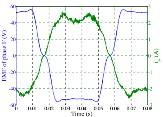
A six-pole seven-phase NN TORUS [18] machine with two external rotors was designed [19]. Fig. 1 shows one sixth of the proposed axial flux seven-phase machine. The stator, with Gramme-ring windings, is made from soft magnetic composite and contains 42 slots (Fig. 2). Its external diameter measures 287mm and its thickness is 123mm. Other data are given in the appendix.
B. Design of the seven-phase axial flux machine
When two phases are open-circuited, two currents are set to zero and can no longer be controlled. Current vector iG then becomes a four-dimensional vector (7-1-2=4). Consequently, due to the fact that there are only four remaining degrees of freedom, it is possible to impose the current vector iJJGMk in only two of the three two-phase fictitious machines.
For one two-phase machine, it is thus impossible to choose the values of the currents. If the EMF vector of this non-controlled machine is not equal to zero, according to (5) torque ripples are then induced. Therefore, the drive has been designed in order to minimize the harmonics of this uncontrollable machine in fault operation.
We have chosen to cancel the EMF of fictitious machine
M2 among the three machines because M1 and M3 have more potential for torque production since the main harmonics associated with these machines are the first and the third ones.
To eliminate the fifth harmonic from the fictitious machine
M2, a 4/5 pole arc within the magnet distribution (see Fig. 2) has been set up.
This approach is not possible with a five-phase machine with a third harmonic because the second machine is associated mainly with this third harmonic. With a wye-coupled six-phase machine the third harmonic cannot be used. So it appears that seven is the minimum number of phases that allows to use simultaneously the first and the third harmonics while maintaining two degrees of freedom to be able to work easily with one or two open-circuited phases. From this point of view, induction machines are more interesting since the third harmonic is depending on the control of the magnetizing current. It is possible to use a third harmonic in normal operation and to suppress it in fault mode operation.
C. Characterization of the seven-phase axial flux machine
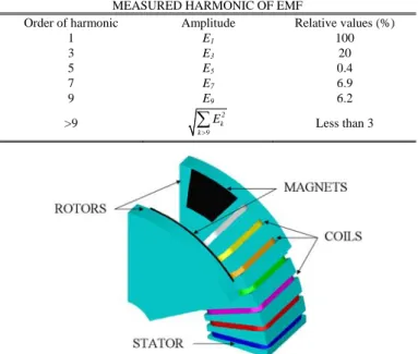
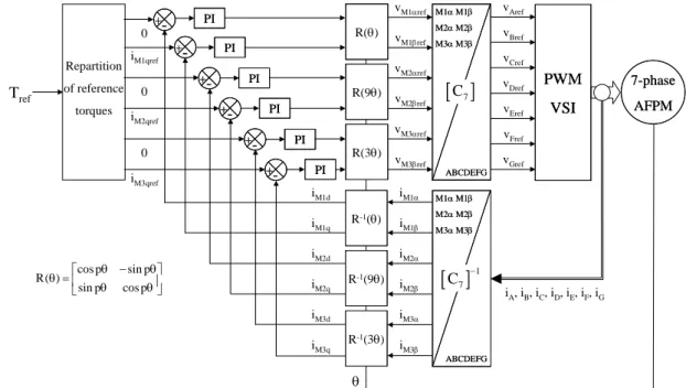
Fig. 3 shows the EMF of one phase with the associated harmonic spectrum presented in Table II. Thus, taking into account the distribution of the harmonics given in table I, it can be considered that the EMF of each fictitious machine is sinusoidal. With respect to machine M2, the fifth harmonic is almost equal to zero as required. However the ninth harmonic, which still represents 6.2% of the first harmonic, will continue to induce torque ripples in the machine in fault mode configuration.
TABLE II
MEASURED HARMONIC OF EMF
Order of harmonic Amplitude Relative values (%)
1 E1 100 3 E3 20 5 E5 0.4 7 E7 6.9 9 E9 6.2 >9 k2 k 9 E >
∑
Less than 3Fig. 1. One sixth of the axial flux seven-phase machine.
0 0.01 0.02 0.03 0.04 0.05 0.06 0.07 0.08 -60 -40 -20 0 20 40 60 Time (s) E M F of ph as e F (V) 0 0.01 0.02 0.03 0.04 0.05 0.06 0.07 0.08-3 -2 -1 0 1 2 3 i F (A)
Fig. 3. Measured EMF (---) and current of phase F in normal mode at 250rpm for a 23.9Nm torque.
IV. MACHINETORQUECONTROL A. Normal operation
Considering that the EMF of each fictitious machine is mainly composed of one harmonic, the associated EMF vectors can be expressed as:
( ) ( )
(
)
( ) ( )(
)
( ) M 1 M 1 M 1 M 1 M 1 M 1 M 1 M 1 M 2 M 2 M 2 M 2 M 2 M 2 M 2 M 2 M 3 M 3 M 3 M 3 M 3 M 3 M 3 e e x e x E sin x cos x e e x e x E sin 9 x cos 9 x e e x e x E sin 3 x c α α β β α β α α β β α β α α β β α θ θ θ θ θ = + = − = + = − = + = − JJJG JJJJJG JJJJJG JJJJJG JJJJJG JJJG JJJJJG JJJJJG JJJJJG JJJJJG JJJG JJJJJG JJJJJG JJJJJG ( )(
os 3θ xM 3β)
JJJJJG (6)with θ the electrical angle.
According to (5), the electromechanical conversion is expressed by: M 1 M 1 M 1 M 2 M 2 M 2 M 3 M 3 M 3 M 1 M 2 M 3 e .i T ; e .i T ; e .i T T T T T Ω Ω Ω = = = = + + JJJG JJJG JJJG JJJG JJJG JJJG (7) To get the maximum average torque for given copper losses, the waveform of current and EMF must be the same [20]. With the vectorial approach this property appears easily: as the torque is the dot product of current and EMF vectors (see (7)), the maximum value is obtained when the current vector is co-linear with the EMF vector.
If control of the currents is achieved in the natural reference frame, the current references are not constant and have a complex waveform: PI controllers are then not well-adapted, when the speed increases, because of their low bandwidth.
However, since the subspaces are orthogonal to each other, it is quite easy to express the condition of co-linearity between current and EMF vectors: the components of these vectors in the subspaces must be also co-linear. As the waveforms of EMF are simpler in the subspaces, the control of currents is facilitated.
In the proposed control, only the first and the third harmonics of EMF are used to produce torque. Then a constant torque is obtained by imposing vectors iJJJGM 1, iJJJGM 2 and iJJJGM 3 such that:
( ) ( )
(
)
( ) ( )(
)
M 1 M 1 M 1 M 1 M 1 M 1 M 1 M 1 M 2 M 2 M 2 M 2 M 2 M 3 M 3 M 3 M 3 M 3 M 3 M 3 M 3 i i x i x I sin x cos x i i x i x 0 i i x i x I sin 3 x cos 3 x α α β β α β α α β β α α β β α β θ θ θ θ = + = − = + = = + = − JJJG JJJJJG JJJJJG JJJJJG JJJJJG JJJG JJJJJG JJJJJG G JJJG JJJJJG JJJJJG JJJJJG JJJJJG (8)Fig. 3 shows the corresponding experimental current in one phase for a case with IM 1=5A and IM 3=k IM 1with
M 3 M 1
k=E / E =0.2 (see table II). This condition ensures the co-linearity between the EMF and current vectors. The difference between the two waveforms in Fig. 3 is due to the presence of the fifth and higher harmonics in the EMF.
Resulting torque is expressed by:
M 1 M 1 M 3 M 3 M 1 M 1 M 3 M 3 N e .i e .i E I E I T Ω Ω + + = = JJJG JJJG JJJG JJJG (9) and associated copper losses in normal mode are:
(
2 2)
C N M 1 M 3
P− =R I +I (10)
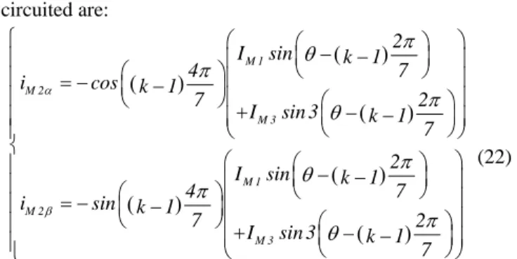
Since the EMFs of each fictitious machine have a dominant harmonic, rotation operators R(α) are used and this leads to a situation where the variables are constant in steady state. PI current controllers are then quite adapted for each fictitious machine and constant current references (so-called dq references) lead to a constant torque in steady state. Fig. 4 depicts the overall structure of the chosen torque control.
Fig. 5 gives the electromagnetic torque in normal operation (T1) for IM 1=5A and IM 3=1A. The mean torque is equal to
N
T
< > = 23.9Nm with maximum peak-to-peak torque ripples equal to ΔTN = 3.4Nm (0.052 p.u.).
B. Fault operation with open-circuited phases 1) Chosen strategy
The first chosen constraint is to keep the same control structure as in normal operation: three PI controllers are used in the three dq frames associated with the EMF of each fictitious machine. This choice is interesting from the point of view of a practical implementation because of its simplicity: the possibility to use only one structure of control whose qualities are well known in normal mode operation.
The second constraint is to cancel the torque pulsations that appear in fault mode. In some applications, sensitive to mechanical resonances or vibrations, it is effectively much more important to keep weak torque pulsations rather than maintaining a high level of average torque.
The last constraint is to reduce as far as possible the copper losses. However, this constraint is not a priority since it is possible to satisfy the thermal constraints by imposing an adequate value for the average torque: the system is then generally still working but at lower speed.
Of course, if a constant torque is required, even with open-circuited phases, it is necessary to recalculate new current references. In the natural frame the current waveforms are rather complex. With the chosen structure of control and with sinusoidal EMFs in M1 and M3 machines, it is then sufficient to impose sinusoidal currents in M1 and M3 machines in order to get a constant torque in these machines. In the dq frames associated with the EMFs of M1 and M3, the references of currents are then constant in steady state and PI controllers remain sufficient. The voltage references vM 1 refα , vM 1 refβ ,
M 3 ref
v α , vM 3 refβ are thus determined (Fig. 4) by PI controllers working in ideal conditions.
There remains to choose two voltage references vM 2 refα ,
M 2 ref
v β . As the EMF of M2 is supposed to be negligible, any
currents can exist in M2 without effect on the torque.
When two phases are opened, the currents in M2 are
completely determined since the currents in M1 and M3 have
been already chosen and two real currents are equal to zero. The two voltage references vM 2 refα , vM 2 refβ are then generated by the PI controllers of M2 when the current
references in M2 are imposed.
When only one phase is opened, it remains one degree of freedom that is used to minimize the copper losses in M2
machine.
The last point to consider is the repartition of the torque between the M1 and M3 machines. In normal mode, it has
been shown that the optimal value of the ratio k=IM 3/ IM 1 is equal to EM 3/ EM 1. In fault mode operation a new optimal ratio kopt will be calculated to ensure minimum copper losses.
2) Case of one open-circuited phase
If one phase is open-circuited, current vector iGbecomes a five-dimensional vector (7-1-1=5). If it is considered, for example, that phase B is open-circuited (iB = ), i0 G is expressed by:
A A C C D D E E F F G G
i=i x +i x +i x +i x +i x +i x G JJG JJG JJG JJG JJG JJG
(11) with i the current and j xj
JJG
the orthonormal vector of phase j. Or, using the multi-machine concept:
= M 1+ M 2+ M 3
i i i i
G JJJG JJJG JJJG
(12) Calculating the dot product of (11) and (12) with xJJGBand using the property of orthogonality, it comes:
(
)
B A A C C D D E E F F G G B i . x = i x +i x +i x +i x +i x +i x . x =0 G JJG JJG JJG JJG JJG JJG JJG JJG (13) and:(
)
B M 1 M 2 M 3 B i . x = i +i +i . x G JJG JJJG JJJG JJJG JJG (14) Combining (13) and (14) gives the following results:(
iM 1+iM 2+iM 3)
. xB=0JJG JJJG JJJG JJJG
(15) Keeping the same sinusoidal references for iJJJGM 1 and iJJJGM 3 as in (8), (15) becomes: + + + + + = M 1 M 1 B M 1 M 1 B M 2 M 2 B M 2 M 2 B M 3 M 3 B M 3 M 3 B i x x i x x i x x i x x i x x i x x 0 α α β β α α β β α α β β JJJJJGJJG JJJJJGJJG JJJJJGJJG JJJJJGJJG JJJJJGJJG JJJJJGJJG (16) To reduce the extra copper losses due to currents in M2, M 2
iJJJG must have the lowest modulus possible:
2 2
M 2 M 2 M 2 M 2
i .i =i α +i β ≤max JJJG JJJG
(17) Combining (16) and (17) leads to a system that can be
θ 0 0 0 vM1αref vM1βref vM2αref vM2βref vM3αref vM3βref vAref vBref vCref vDref vEref vGref vFref 7-phase AFPM 7-phase AFPM PWM VSI PWM VSI R(9θ) R(θ) R(3θ) R(9θ) R(9θ) R(θ) R(θ) R(3θ) R(3θ) R-1(9θ) R-1(θ) R-1(3θ) R-1(9θ) R-1(9θ) R-1(θ) R-1(θ) R-1(3θ) R-1(3θ) PI PI -+ -+ -+ -+ iM1qref PIPI PI PI -+ -+ -+ -+ iM2qref PIPI PI PI -+ -+ -+ -+ iM3qref PIPI iA, iB, iC, iD, iE, iF, iG M1α M1β M2α M2β M3α M3β ABCDEFG M1α M1β M2α M2β M3α M3β ABCDEFG M1α M1β M2α M2β M3α M3β ABCDEFG M1α M1β M2α M2β M3α M3β ABCDEFG iM1α iM1β iM2α iM2β iM3α iM3β iM1d iM1q iM2d iM2q iM3d iM3q Repartition of reference torques Tref cos p sin p R( ) sin p cos p θ − θ ⎡ ⎤ θ = ⎢ θ θ⎥ ⎣ ⎦
[ ]
C7[ ]
1 7 C −easily solved:
(
)
(
)
(
)
(
)
(
)
(
)
+ ⎧ ⎪ + + ⎪ ⎨ + + = ⎪ ⎪ + ≤ ⎩ M 1 M 1 M 2 M 2 M 3 M 3 2 2 M 2 M 2 cos 2 7 i sin 2 7 i cos 4 7 i sin 4 7 i cos 6 7 i sin 6 7 i 0 i i max α β α β α β α β π π π π π π (18)That leads to:
(
)
(
(
)
)
(
)
(
(
)
)
M 1 M 2 M 3 M 1 M 2 M 3 I sin 2 7 i cos 4 7 I sin 3 6 7 I sin 2 7 i sin 4 7 I sin 3 6 7 α β θ π π θ π θ π π θ π ⎧ ⎛ − ⎞ = − ⎪ ⎜⎜ ⎟⎟ + − ⎪ ⎝ ⎠ ⎨ ⎛ − ⎞ ⎪ = − ⎜ ⎟ ⎪ ⎜+ − ⎟ ⎝ ⎠ ⎩ (19)With these currents in M2 machine, the total copper losses are equal to:
(
2 2 2)
(
2 2)
C F _ 1 M 1 M 3 M 2 M 1 M 3
P− =R I +I +I =1.5 R I +I (20)
In order to minimize the total copper losses for a given torque
TN, it is sufficient to express PC F _ 1− by using expressions of
torque TN and ratio k. Using (9), (20) becomes:
(
)
(
)
(
)
(
)
2 2 2 N C F _ 1 2 2 C N M 1 1 k 1.566 1 k T P 1.5R P E 1 0.2k 1 0.2k Ω − − + + ⎛ ⎞ = ⎜ ⎟ = + + ⎝ ⎠ (21)This function is minimum for kopt =0.2. This optimum value is the same as in normal mode. The copper losses for a same torque as in normal mode correspond then to 1.5 of the losses
C N
P− that have been calculated in normal mode. Taking into
account the global thermal constraint accepted by the drive, the torque reference or the current references (IM 1 and IM 3) must therefore be adjusted. As an example, if the required torque is, as discussed in [1], 6/7 of T then N
C F _ 1 C N
P− =1.1 P− .
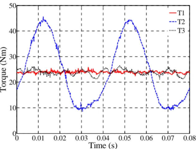
Fig. 5 shows that, with one open-circuited phase and keeping the same current references as in normal mode, torque ripples occur (T2). Imposing the new current references (19) for M2, torque ripples greatly decrease (T3). However, the total torque ripples in fault-condition (T3) are not equal to zero as in theory. Two main reasons are at the origin of the observed torque ripples with the experimental machine:
- EMFs of M2 are not equal to zero (table II);
- real currents are not exactly equal to the references.
Fig. 6 shows the currents in fictitious machines M1, M2 and
M3. Due to the fact that the current references of machine M2 are not constant and that PI controllers have a limited bandwidth, the fictitious currents are not exactly as expected: a maximum error of 6% on the RMS values of the currents of
M1 and M2 has been calculated. Consequently, the total torque in fault-condition (T3) has ripples. Finally, Fig. 7 shows that the real measured phase currents have been redistributed to obtain a constant torque and present an unbalance of maximal amplitudes from 2.5A to 4A. The corresponding calculated RMS values of the currents vary from 2.1A to 2.9A. This dispersion implies that a
determination of the new acceptable average torque can not be only based on the global calculated extra-losses. A thermal analysis of the local losses density should be necessary in order to determine precisely the maximum value of the required torque.
Using the same calculation technique, the new current references (iM 2αand iM 2β) when phase k
(
k∈[ ]
1,7)
is open-circuited are: ( ) ( ) ( ) ( ) ( ) ( ) ⎧ ⎛ ⎛ − ⎞ ⎞ − ⎜ ⎟ ⎪ ⎛ ⎞⎜ ⎝ ⎠ ⎟ ⎪ = − ⎜ − ⎟⎜ ⎟ ⎪ ⎝ ⎠⎜+ ⎛ − ⎞⎟ − ⎜ ⎟ ⎪ ⎜ ⎝ ⎠⎟ ⎪ ⎝ ⎠ ⎨ ⎛ ⎛ ⎞ ⎞ ⎪ ⎜ − − ⎟ ⎜ ⎟ ⎪ ⎛ ⎞⎜ ⎝ ⎠ ⎟ = − ⎪ ⎜⎝ − ⎟⎜⎠ ⎟ ⎛ ⎞ ⎪ + ⎜ − − ⎟ ⎜ ⎟ ⎪ ⎝ ⎝ ⎠⎠ ⎩ M 1 M 2 M 3 M 1 M 2 M 3 2 I sin k 1 7 4 i cos k 1 7 2 I sin 3 k 1 7 2 I sin k 1 7 4 i sin k 1 7 2 I sin 3 k 1 7 α β π θ π π θ π θ π π θ (22)Irrespective of the open-circuited phase, the extra copper losses are the same.
In Table III are summarized experimental results on the torque ripples and the extra copper losses for one open-circuited phase. The 44% of extra losses obtained using measured real currents can be considered in accordance with the 50% predetermined in (21). The 22% torque ripples are weak in comparison with the 155% obtained without modification of the control. However, these ripples should be equal to zero if the current controller for the M2 machine had an infinite bandwidth and if the EMF had only the first, third and fifth harmonics.
3) Case of two open-circuited phases
In the case of two open-circuited phases, the same method as presented for one open-circuited phase is used but with no choice concerning the currents in M2 machine. Current vector
i G
, which becomes a four-dimensional vector (7-1-2=4), is then multiplied by the two orthonormal vectors associated with the open-circuited phases. To find the new M2 current references, it is enough to solve a simple system composed of two equations and two unknowns.
Due to the regular circular distribution of the phases, only three cases are considered:
− two consecutive phases are open-circuited ( 2 7π ), named (BC) case;
− two phases displaced by ( 4 7π ) are open-circuited, named (BD) case;
− two phases displaced by ( 6 7π ) are open-circuited, named (BE) case.
0 0.01 0.02 0.03 0.04 0.05 0.06 0.07 0.08 0 10 20 30 40 50 Time (s) T o rque (N m ) T1 T2 T3
Fig. 5. Torques in normal operation (T1), with open-circuited phase B and the same current references as in normal mode (T2), with the new current
references according to the chosen strategy (T3).
0 0.01 0.02 0.03 0.04 0.05 0.06 0.07 0.08 -8 -6 -4 -2 0 2 4 6 8 Time (s) C u rr en t (A ) i M1α iM1β iM2α iM2β iM3α iM3β
Fig. 6. Currents of M1, M2 and M3 machines when phase B is
open-circuited with the new current references.
0 0.01 0.02 0.03 0.04 0.05 0.06 0.07 0.08 -8 -6 -4 -2 0 2 4 6 8 Time (s) Cu rr en t ( A ) i A iB iC iD iE iF iG
Fig. 7. Currents of the seven-phase machine when phase B is open-circuited with the new current references.
If, for example, phases B and C ( 2π 7) are open-circuited the system to solve is the following:
+ + + + + = + + + + M 1 M 1 B M 1 M 1 B M 2 M 2 B M 2 M 2 B M 3 M 3 B M 3 M 3 B M 1 M 1 C M 1 M 1 C M 2 M 2 C M 2 M 2 C i x x i x x i x x i x x i x x i x x 0 i x x i x x i x x i x x i α α β β α α β β α α β β α α β β α α β β JJJJGJJG JJJJJGJJG JJJJJGJJG JJJJJGJJG JJJJJGJJG JJJJJGJJG JJJJGJJG JJJJJGJJG JJJJJGJJG JJJJJGJJG ⎧ ⎪ ⎪ ⎪ ⎪⎪ ⎨ ⎪ ⎪ ⎪ ⎪ + = ⎪⎩ M 3αxM 3αxC iM 3βxM 3βxC 0 JJJJJGJJG JJJJJGJJG (23) or :
(
)
(
)
(
)
(
)
(
)
(
)
(
)
(
)
(
)
(
)
(
)
(
)
+ ⎧ ⎪ + + ⎪ ⎪+ + = ⎪ ⎨ + ⎪ ⎪+ + ⎪ ⎪+ + = ⎩ M 1 M 1 M 2 M 2 M 3 M 3 M 1 M 1 M 2 M 2 M 3 M 3 cos 2 7 i sin 2 7 i cos 4 7 i sin 4 7 i cos 6 7 i sin 6 7 i 0 cos 4 7 i sin 4 7 i cos 8 7 i sin 8 7 i cos 12 7 i sin 12 7 i 0 α β α β α β α β α β α β π π π π π π π π π π π π (24)That leads to:
( ) ( )
(
)
( ) ( )(
)
( ) ( )(
)
( ) ( )(
)
= ⎧ − ⎪ + + ⎪ ⎨ = − + ⎪ ⎪ + + ⎩ M 2 M 1 M 3 M 2 M 1 M 3 i I 0.055 sin 1.323 cos I 0.222 sin 3 0.589 cos 3 i I 0.627 sin 0.5 cos I 0.975 sin 3 0.579 cos 3 α β θ θ θ θ θ θ θ θ (25)If phases B and D ( 4π 7) are open-circuited, new iM 2α and
M 2 i β references are: ( ) ( )
(
)
( ) ( )(
)
( ) ( )(
)
( ) ( )(
)
= ⎧ + ⎪ + + ⎪ ⎨ = − + ⎪ ⎪ + + ⎩ M 2 M 1 M 3 M 2 M 1 M 3 i I 0.901 sin 2.384 cos I 2.123 sin 3 2.972 cos 3 i I 0.434 sin 1.346 cos I 1.409 sin 3 1.123 cos 3 α β θ θ θ θ θ θ θ θ (26)And for open-circuited phases B and E ( 6π 7):
( ) ( )
(
)
( ) ( )(
)
( ) ( )(
)
( ) ( )(
)
= ⎧ − ⎪ − + ⎪ ⎨ = − + ⎪ ⎪ + + ⎩ M 2 M 1 M 3 M 2 M 1 M 3 i I 1.747 sin 1.323 cos I 0.623 sin 3 1.65 cos 3 i I 0.241 sin 0.5 cos I 0.782 sin 3 0.068 cos 3 α β θ θ θ θ θ θ θ θ (27)Contrary to the case of one open circuited phase, the amount of copper losses depends on which two open-circuited phases are considered. Using (9), (25), (26) and (27), the total copper losses are calculated for given torque TN and ratio k:
( )
(
)
( )(
)
( )(
)
2 2 N C F _ 2 2 7 2 M 1 2 2 N C F _ 2 4 7 2 M 1 2 2 N C F _ 2 6 7 2 M 1 T 1 0.8376 k P 2.2 E 1 0.2k T 1 1.7716 k P 5.24 E 1 0.2k T 1 0.805k P 3.55 E 1 0.2k π π π Ω Ω Ω − − − ⎡ ⎤ + = ⎢ ⎥ + ⎣ ⎦ ⎡ ⎤ + = ⎢ ⎥ + ⎣ ⎦ ⎡ ⎤ + = ⎢ ⎥ + ⎣ ⎦ (28)As the level of losses is depending on ratio k, optimal value has been calculated for each case and copper losses PC F _ 2−
are expressed with PC N− . The results are: ( ) ( ) ( ) C N opt C F _ 22 7min C N opt C F _ 24 7min C N opt C F _ 26 7min P 2.18 P for k 0.248 P 5.36 P for k 0.117 P 3.52 P for k 0.258 π π π − − − − − − = = = = = = (29)
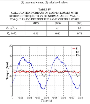
As for the case of one open-circuited phase, Fig. 8 shows the torques obtained when the current references are kept as in normal mode (T2) or using the new calculated references (T3). It appears that the torque ripples are also drastically reduced.
The currents shown in Fig. 9 are close to the references calculated in (19) for M2 and in (8) for M1 and M3: the errors between the RMS values of the reference and measured currents are less than 7% for the M1, M2 and M3 machines. Fig. 10 shows that the phase currents are redistributed in order to keep the torque constant. As for one open phase, an unbalance between the different current amplitudes exists: the calculated RMS value of the currents varies from 2.6 A to 4.4 A.
Concerning the torque, it appears in table III that the amplitudes of the torque pulsations have been sharply reduced but are not equal to zero since the experimental machine does not satisfy perfectly the assumptions. It appears also that the reduction of torque in order to keep acceptable copper losses is depending on the open-circuited phases.
Concerning the ratio of losses PC F− PC N− , table III shows
that differences between experimental and calculated values are less than to 12%.
In table IV, the first line concerns the cases with two open-circuited phases. A new ratio PC F− PC N− is calculated by considering a reasonable required torque equal to 5/7 of the torque T N required in normal mode. In line two of table IV, the torque TFC that should be required in order to keep the same level of copper losses PC N− obtained with 5/7 T is N
calculated. It can be remarked that (BD) case leads to a reduction down to 60% of the torque T . Cancellation of the N
torque pulsations appears then to be a severe constraint for this (BD) case. Looking at the table III, it appears also that (BD) is the case with the weakest torque pulsations when the control is unchanged in fault operation. But with the improved control, the reduction of the torque pulsations is not as well noticeable as for the other cases. On the contrary, the increase of copper losses is much more important. Instead of imposing the cancellation of the torque pulsation it should be preferable to impose maximum acceptable amplitude of the torque pulsations.
TABLE III
COMPARISON BETWEEN ELECTROMAGNETIC TORQUE RIPPLES AND COPPER LOSSES WITH AND WITHOUT NEW CALCULATED
CURRENT REFERENCES Same current
references New current references
Open-circuited Phases N T T Δ < > (1) C F C N P P − − (1) N T T Δ < > (2) N T T Δ < > (1) C F C N P P − − (1) C F C N P P − − (2) (B) 1.55 1.64 0 0.22 1.44 1.5 (BC) 1.37 0.95 0 0.31 2.06 2.18 (BD) 0.86 0.63 0 0.52 4.90 5.36 (BE) 1.64 0.88 0 0.52 3.12 3.52 (1) measured values; (2) calculated values
TABLE IV
CALCULATED INCREASE OF COPPER LOSSES WITH REDUCED TORQUE TO 5/7 OF NORMAL-MODE VALUE.
TORQUE RATIO KEEPING THE SAME COPPER LOSSES
(BC) (BD) (BE) C F C N P− P− 1.1 2.7 1.8 5 FC 7 N T T 0.95 0.60 0.74 0 0.01 0.02 0.03 0.04 0.05 0.06 0.07 0.08 0 10 20 30 40 50 Time (s) T o rque (Nm ) T1 T2 T3
Fig. 8. Torques in normal operation (T1),
with open-circuited phases BC and with the same current references as in normal mode (T2) and with the new current references (T3).
0 0.01 0.02 0.03 0.04 0.05 0.06 0.07 0.08 -8 -6 -4 -2 0 2 4 6 8 Time (s) C u rre n t (A ) i M1α iM1β iM2α iM2β iM3α iM3β
Fig. 9. Currents of M1, M2 and M3 where phases BC are open-circuited
0 0.01 0.02 0.03 0.04 0.05 0.06 0.07 0.08 -8 -6 -4 -2 0 2 4 6 8 Time (s) Cu rr en t ( A ) i A iB iC iD iE iF iG
Fig. 10. Currents of the seven-phase machine with open-circuited phases BC and with the new current references.
V. CONCLUSION
In this paper fault tolerance for a specially designed seven-phase machine has been validated. One of the advantages of this kind of drive is that neither the structure of the control nor the PI controllers have to be changed between normal and fault operations. Practical implementation with high power drives using PI controllers and PWM with constant carrier frequency can be carried out without difficulty. It is only necessary to modify one set of dq current references in order to drastically reduce the torque ripples that appear when one or two phases are opened. Experimental results confirm the validity of the simple proposed solution concerning the torque ripples in fault mode.
The amplitude calculus of the necessary torque reduction to maintain acceptable constraints has been made. As the currents are unbalanced and one or two equal to zero, more precise local analysis of the thermal constraints inside the machine must be done. A global calculation of the losses is only an indication. Of course, other controls can obviously be considered to reduce them: a total constant torque can be obtained by combining non-constant torques in M1 and M3 machines. Nevertheless, in this case, the use of PI controllers leads to errors when the speed increases.
Finally, the developed study could be pursued by taking into account an acceptable level of torque ripples in order to find a compromise between increase of copper losses and reduction of torque ripples.
VI. REFERENCES
[1] E. Levi, “Multiphase Electric machines for Variable Speed Applications”, IEEE Trans. on Industrial Electronics, in press.
[2] S. Siala, E. Guette and J. L. Pouliquen, “Multi-inverter PWM control: a new generation drives for cruise ship electric propulsion”, Proc. of EPE’03, Toulouse (France), Sept. 2003, CD-ROM.
[3] G. Simões and P. Vieira, “A High-Torque Low-Speed Multiphase Brushless Machine - A Perspective Application for electric vehicles”,
IEEE Trans. on Industrial Electronics, vol. 49, no. 5, Oct. 2002, pp.
1154-1164.
[4] M. Abolhassani, “A novel Multiphase Fault Tolerant High Torque Density Permanent Magnet Motor Drive for Traction Application”,
Proc. of IEEE-IEMDC'05, San Antonio (USA), May 2005, pp. 728-734.
[5] J. W. Bennett, A. G. Jack, B. C. Mecrow, D. J. Atkinson, C. Sewell and G. Mason, “Fault-tolerant Control Architecture for an Electrical Actuator”, Proc. of IEEE-PESC’04, vol. 6, Aachen (Germany), June
2004, pp. 4371-4377.
[6] J. Wang, K. Atallah and D. Howe, “Optimal torque control of fault-tolerant permanent magnet brushless machines”, IEEE Trans. on Magnetics, vol. 39, no. 5, Sept. 2003, pp. 2962-2964.
[7] T. M. Jahns, “Improved reliability in solid state ac drives by means of multiple independent phase-drive units”, IEEE Trans. on Industry Applications, vol. IA-16, May-June 1980, pp. 321-331.
[8] H. M. Ryu, J. H. Kim and S. K. Sul, “Synchronous-Frame Current Control of Multiphase Synchronous Motor Under Asymmetric Fault Condition due to Open Phases”, IEEE Trans. on Industry Applications,
vol. 42, n°4, July/August 2006, pp.1062-1070.
[9] J.R Fu, T.A. Lipo, 'Disturbance free operation of a multiphase current regulated motor drive with an opened phase', IEEE Trans. on Industry Applications, vol. 30, no. 5, pp. 1267-1274, 1994.
[10] C.B. Jacobina, I.S. Freitas, T.M. Oliveira, E.R.C. da Silva, A.M.N. Lima, 'Fault tolerant control of five-phase AC motor drive', Proc. of IEEE-PESC’04, Aachen (Germany), June 2004, pp. 3486-3492.
[11] L. Parsa and H. A. Toliyat, “Fault-Tolerant Five-Phase Permanent Magnet Motor Drives”, Proc. of IEEE-IAS’04, vol.2, pp. 1048-1054,
Seattle (USA), Oct. 2004.
[12] N. Bianchi, S. Bolognani, M. Dai Pre, “Design and Tests of a Fault-Tolerant Five-phase Permanent Magnet Motor”, Proc. of IEEE-PESC’06, Jeju (Korea), 18-22 June 2006, pp.1-8.
[13] E. Semail, X. Kestelyn, and A. Bouscayrol, “Right Harmonic Spectrum for the back-electromotive force of a n-phase synchronous motor”, Proc. of IEEE-IAS’04, vol. 1, pp.71-78, Seattle (USA), Oct. 2004.
[14] F. Locment, E. Semail and F. Piriou, “Design and Study of a Multi-phase Axial-flux machine”, IEEE Trans. on Magnetics, vol. 42, no. 4,
pp. 1427-1430, April 2006.
[15] H. M. Ryu, J. W. Kim and S. K. Sul, “Synchronous Frame Current Control of Multi-Phase Synchronous Motor, Part I. Modeling and Current Control Based on Multiple d-q Spaces Concept Under Balanced Condition”, Proc. of IEEE-IAS’04, vol. 1, pp. 56-63, Seattle (USA), Oct.
2004.
[16] Y. Zhao and T. Lipo, “Space Vector PWM Control of Dual Three-Phase Induction Machine Using Space Vector Decomposition”, IEEE Trans. on Industry Applications, vol. 31, no. 5, Sept./Oct. 1995, pp. 1100-1109.
[17] D. C. White and H. H. Woodson, "Electromechanical Energy Conversion", John Wiley and Sons, 1959, chap IX.
[18] S. Huang, M. Aydin and T. A. Lipo, “TORUS Concept Machines: Pre-Prototyping Assessment for Two Major Topologies”, Proc. of IEEE-IAS’01, Chicago (USA), Oct. 2001, pp. 1619-1625.
[19] F. Locment, E. Semail and F. Piriou, “Soft Magnetic Composite Axial Flux Seven-Phase Machine”, Proc. of ICEM’06, Chania, (Greece), Sept.
2006, CD-ROM.
[20] J. P. Martin, F. Meibody-Tabar and B. Davat, "Multiple-phase Permanent Magnet Synchronous Machine Supplied By VSIs, working under Fault Conditions", Proc. of IEEE-IAS’00, Roma (Italy), Oct. 2000,
VII. APPENDIX
The PWM is implemented with the classical triangle intersection method
VIII. BIOGRAPHIES
Fabrice Locment is graduated in 2003 from the Ecole Polytechnique Universitaire of Lille in France. He received Ph.D. degree in 2006. He became Associate Professor at Engineering school of UTC in February 2008. His research interests are in design, modelling and control of multi-phase drives (converters and AC machines). (http://fabrice.locment.free.fr/)
Eric Semail is graduated in 1986 from the Ecole Normale Superieure, in France. He received Ph.D. degree in 2000 on « Tools and studying method of Multiphase Electrical systems, Generalization of the space vector theory ». He became Associate Professor at Engineering school of ENSAM in 2001. In Laboratory of Electrical Engineering of Lille (L2EP) in France, his fields of interest include design, modelling and control of multi-phase drives (converters and AC Drives). More generally he studies Multi-machine and Multi-converter systems. (http://eric.semail.free.fr/)
Xavier Kestelyn received the Ph.D. degree in electrical engineering from Lille University, France, in 2003. After ten years as a teacher of electrical engineering in high school, he is currently an Assistant Professor of electrical engineering at engineering school of ENSAM, France. His research interests are in modelling and control of multi-machine systems such as multi-phase machines and over-actuated industrial robots. (http://xavier.kestelyn.free.fr/)