Light Node Communication Framework : a new way
to communicate inside a Smart Home
Valère Plantevin1, Abdenour Bouzouane2and Sebastien Gaboury3
1 UQAC; [email protected] 2 UQAC; [email protected] 3 UQAC; [email protected] * Correspondence: [email protected]
Version November 7, 2017 submitted to Sensors; Typeset by LATEX using class file mdpi.cls
Abstract: The Internet of Thing has profoundly changed the way we imagine information science
1
and architectures and Smart Homes are an important part of this domain. Created a decade ago, the
2
few existing prototypes use the technologies of the day forcing designers to create centralized and
3
costly architectures that raise some issues concerning the reliability, the scalability and ease of access
4
which cannot be tolerated in an assistance context. In this paper we briefly introduce a new kind
5
of architecture where the focus was placed on the distribution and especially. More specifically,
6
we answer the first issue we met by proposing a lightweight and portable messaging protocol.
7
After running several tests, we observed a maximized bandwidth, no packets were lost and a good
8
encryption was obtained. These results tend to prove that our innovation may be employed in a real
9
context of distribution on small entities.
10
Keywords:Messaging protocol; IoT; SmartHome; Distributed Computing
11
1. Introduction
12
The evolution of our society towards the all-digital of the Internet of Things (IoT) profoundly
13
remodeled our relationship with the science of information. In this new one, the smart home became
14
the subject of numerous researches [1–3] and joins the recent current of thought stemming from the
15
Ambient Intelligence (Amb. I). This last one refers to a tendency that wants us to miniaturize a set
16
of electronic devices (sensors and effectors) in order to integrate them into any object of everyday life
17
(lamp, refrigerator, etc.) in a transparent way for the person. The aim behind this idea is to supply
18
punctual assistance to the occupants according to the gathered information and to the history of the
19
accumulated data.
20
The vast majority of work in the smart home domain focuses on the activity recognition
21
problem in order to assist the inhabitant with a potential dementia often caused by an advanced
22
age[4–6]. Nevertheless, none of them seems to propose a standard architecture which provides both
23
high-reliability and scalability capabilities at a relative low-cost. And still, high-reliability has to be a
24
mandatory feature of such architecture since the assistance is vital for the inhabitant with a potential
25
dementia. Moreover, as the disease can stay for decades, any work on architecture must take the
26
scalability parameter into account since many sensors or improvements can be realized during the
27
illness evolution. Finally, the low-cost aspect has to be taken into account as the vast majority of the
28
aging population will be located in poor or developing countries by 2050 [7]. As far as we know, this
29
paper is the first focusing on those three points in particular.
30
Here, we briefly introduce a new kind of smart home architecture providing both reliability and
31
scalability based on low-cost smart sensors. To achieve this objective, the first issue we ran into is the
32
difference between all the possible entities in the environment. In fact, our solution has to integrate
33
different operating systems (e.g. Linux or FreeRTOS) running on different hardware (e.g. computer or
34
microcontroller) and using different communication technologies (e.g. Wi-Fi, ZigBee or 6LowPan). To
35
answer these dissimilarities, we have to use a highly portable communication protocol using a broker
36
less architecture to provide the highest reliability. This point will be the main concern of this paper.
37
Even if many protocols exist like MQTT, RabbitMQ or ZeroMQ [8–10] none of them fully answer our
38
requirements since the first two require brokers to work and the last one is based on POSIX sockets
39
and cannot be embedded in some light systems. Consequently, the contribution we make in this paper
40
is a new way to communicate that can be embedded in every system as soon as they implement an
41
IP stack. Our solution provides discovery mechanism, security via AES encryption and two different
42
channels in order to address the difference between configuration messages and data messages.
43
This paper is divided in four sections. The first one will present a state of the art about existing
44
smart homes and their architectures. The second part will cover the technological breakthroughs that
45
the embedded computing has experienced since the creation of the first Smart Homes. Then, the
46
proposed solution will be explained and some tests on the messaging protocol will be presented in
47
the third section. Finally, a conclusion and some future works will end this paper.
48
2. Existing architectures
49
Many smart habitations have been implemented in laboratories since the creation of the ambient
50
intelligence [1,3,11,12]. Each of these projects use the technology of its day to create a testing
51
environment in which the data accessibility was the main challenge. Here, we depict three of those
52
starting with the LIARA and DOMUS, which share the same architecture [12]. We continue this
53
review with the Gator Tech house [3] and CASAS [1]. Finally, we end this part by describing Software
54
Defined Smart Home [13,14], a recently released architecture based on software defined networks.
55
2.1. LIARA and DOMUS
56
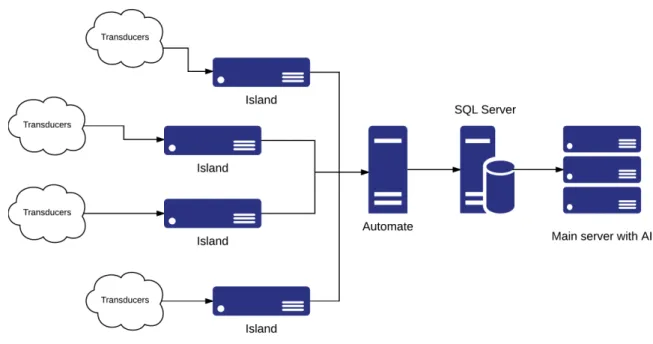
LIARA and DOMUS laboratories aim to study how smart homes can assist people with cognitive
57
deficiencies. They both created a very similar architecture, represented in Figure 1, to test their
58
algorithms and solutions [15]. Inherited from the industry, they use some islands, made of industrial
59
grade hardware, to agglomerate transducers. Then, an automate is in charge of getting back, from
60
the islands, the values of the sensors or changing the values of the effectors. To end this process,
61
the automate will update a relational database hosted on a SQL Server in order to provide a simple
62
interface for other systems like, in this case, an artificial intelligence.
63
These two smart homes present some interesting features we have to discuss. First, the use of
64
industrial grade hardware means that all the components have been tested for a continuous use in
65
a far much harder environment than just a house (e.g. production line in a factory). Therefore it
66
demonstrates an excellent reliability even if the smart home has to operate at all times. The second
67
main advantage of these environments comes from the highly centralized architecture itself. Indeed,
68
all the values coming from sensors and all the actuator controls end up in the same database. As a
69
result, it facilitates interaction with the home since this kind of storage offers an easy way to retrieve
70
sensors values or interact with actuators.
71
Nevertheless, industrial material suffers from two main drawbacks. The first one is the
72
introduction of black boxes in a research environment. As a matter of fact, the communications
73
between all these pieces of hardware often rely on proprietary libraries that can impact future
74
evolution. The second main disadvantage is the price of such an architecture. Based on the hardware
75
presented byBouchard et al.and the price of it, we were able to compute the total price of the chain
76
Island-Automate-Main Server. With 2000 dollars each island [16], 1500 dollars the automate [16] and
77
4000 the server [17], the architecture reaches 13,500 dollars without any transducers or backbone
78
structure (e.g. networking, cooling for the server, maintenance). Finally, the highly centralized
79
architecture presented here creates many Single Points of Failure (SPoFs) like the automate, the
80
Islands and the main server hosting both the AI and the SQL server. So if one of these SPoFs fails,
Figure 1.The LIARA and DOMUS architecture.
at least a quarter of the environment and its assistance will fail too. Moreover, these points represent
82
some serious bottlenecks in the architecture preventing a real scalability.
83
2.2. Gator Tech
84
Gator Tech [3] is a project funded in Florida. Its main goal is to prove the feasibility of a low-cost
85
smart home where the integration of new transducers will be easy. In order to accomplish that the
86
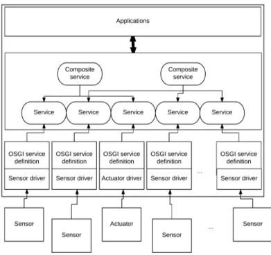
authors present an OSGI [18] based architecture sums up in Figure2. In this last one, each transducer
87
has a simple EEPROM memory containing the driver to communicate with it. Once powered, the
88
transducer registers itself by sending its driver to an OSGI service definition. This last one will act
89
as an abstraction layer to create basic services that allow the consumption of highly abstracted data
90
(e.g. "Sunny" instead of 10 000 lumen for a light sensor) or the combination of basic services to a
91
composite service (e.g. create a voice recognition service on all the different microphone services).All
92
this architecture allows developers to create applications without any knowledge of the underlying
93
communication and with only highly abstracted data which simplify the development.
94
This environment has some really good advantages. First of all, the automatic transducer
95
registration really helps the scalability of such an environment (e.g. add new sensors or replace
96
some of them). Secondly, the high abstraction of the data generates by this system greatly helps
97
the application development. For example, it is straightforward to enable the air conditioning when
98
the temperature is "Hot.” However, it is more complicated when the decision is only based on the
99
microcontroller value since this one depends on the hardware (e.g. the microcontroller itself, the
100
temperature sensor or even the analog to digital chips). Finally, the price of such infrastructure is as
101
low as possible as every transducer is designed to be the most affordable possible by using Atmega128
102
as the main processor unit which is a low-cost platform [19]. Moreover, because every transducer is
103
wireless, there is no need of Islands or Automate as in LIARA and Domus homes. Despite all these
104
great advantages, the use of OSGI on a unique server create a SPoF which is a big problem in a high
105
reliability architecture.
Figure 2.The Gator Tech architecture.
2.3. CASAS
107
CASAS [1], or the Smart Home in a box, is an infrastructure where the accent was put on the price
108
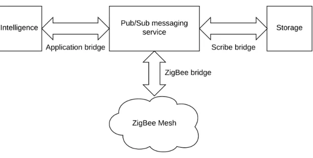
and the ease of installation. Depicted in Figure3, the architecture is divided in four main elements.
109
The first one is the ZigBee mesh which represents all the transducers communicating between them in
110
a network where every node relay the information to its neighbors by using the ZigBee protocol. This
111
mesh sends events on a Publish/Subscribe (Pub/Sub) messaging service through a ZigBee bridge
112
in charge of converting events to higher-level XMPP messages. The messaging service allows other
113
applications to easily integrate the infrastructure and use the transducers. By default, there are two
114
services which are the Storage and the Intelligence. The first archives all the events occurring in the
115
environment by using the Scribe Bridge. As for the intelligence, it is in charge of energy monitoring
116
and the discovery and recognition of any activity that can happen in the house.
117
CASAS has two main benefits : the price and the ease of installation. For the first, the authors
118
present a detailed summary of the cost. They state that their solution cost only 2,765 dollars which
119
is really a great achievement. Regarding the ease of installation, they demonstrate it by conducting a
120
test on people aged from 21 to 62 and it requires only an hour to set up the whole environment. In
121
spit of these qualities, CASAS, as the other architecture, suffer from the existence of many SPoFs like
122
the ZigBee bridge or the Application Bridge which can stop the assistance or the Pub/Sub-messaging
123
service which is a sensitive component.
124
2.4. Software Defined Smart Home
125
The works previously described are the old founders of the Smart Home architecture. However,
126
some more recent papers exist in this particular domain [13,14]. One of them introduce the idea
127
of Software Defined Smart Home or SDSH for short [13]. This concept is a new way to integrate
128
heterogeneous smart appliances (e.g. Smart Light, Smart Flowerpot, etc.) in one homogeneous
129
platform creating a Smart Home from the chaos of the different hardwares and communication
130
protocols implemented by the companies who create these devices. To achieve such a goal, the
131
authors propose a three layers architecture derived from software defined networks [20]. First, the
132
Smart Devices layer includes all the different kinds of smart hardware in a home (a.k.a. the smart
Figure 3.The CASAS architecture.
appliances). Next, the controller layer is a centralized management service locally implemented or
134
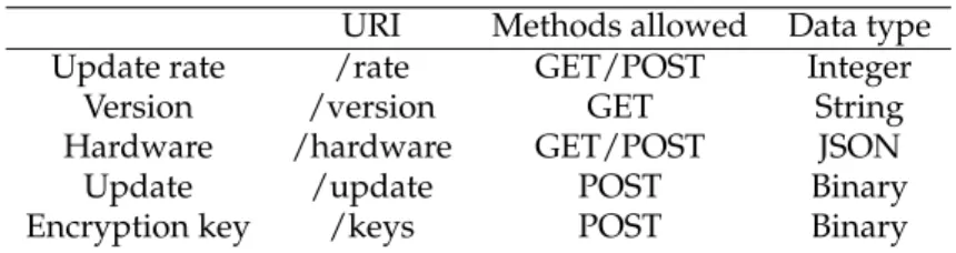
deployed in the cloud. Its main goal is to hide the implementation details of the hardware layer,
135
retrieve and analyze the user demands and manage the whole smart home. Moreover, it is in charge
136
of encapsulates information extracted from the smart home and provide them to the last layer : the
137
external service layer. This last one uses the smart home resources to provide some smart services
138
like home security or medical attention.
139
SDSH offers some great features. First of all, as Gator Tech, this architecture offers a strong
140
separation between raw sensors and final services via its controller layer. Next, it uses OpenFlow
141
[21] as its main protocol which is a well-known protocol widely implemented in software defined
142
network. Finally, it uses smart appliances already in the market and standardize the access to their
143
data. Unfortunately, the centralized controller depicted as one of the main advantages of this work
144
is also a great default because, if it allows to configure the whole Smart Home at the same place,
145
it represents a severe single point of failure. To answer this problematic, the authors introduced
146
visualization techniques but these one require either an Internet cloud connection (which cannot be
147
tolerated in some applications) or a server strong enough to deal with many systems started on the
148
same hardware which can be very expensive for a single house.
149
2.5. Conclusion on existing architectures
150
All these existing architectures have some common points. First the majority of their components
151
are transducers. Moreover, according to the Gator Tech and CASAS cases, it seems that embed
152
some intelligence and communication abilities in them helps to reduce costs and ease installation
153
and scalability. Finally, we have to point out the common problem in all these architectures: the
154
centralization. This weakness creates single points of failure which can lead to a complete stop of the
155
assistance. In corporate computing and Web domains, this particular issue has been solved ten years
156
ago by using redundancy, clusters and distributed computing [22–25].
157
The ideal architecture appears to be composed of many smart transducers easing the scalability
158
of such architecture. This specific attribute bring our environment closer to another computer science
159
domain which is the Internet of Things (IoT). In this last one, already used in the Smart Home [26,27],
160
a multitude of smart objects communicate in a uniform manner and generates a huge amount of data
161
often associate to "Big Data" [28]. In this last case, it is not conceivable to handle the information in a
162
centralized way any more, even if we use server clusters. It is more appropriate to use decentralized
methods relocating the intelligence as close as possible to the units composing this huge data pool 164 [28,29]. 165 3. Technological breakthroughs 166
The transducers (i.e. sensors and actuators) are the essential basis of every Smart Home
167
architecture. CASAS and Gator Tech case studies proved that embed intelligence and communication
168
in these entities allow to reduce costs while improving the ease of implementation and the scalability.
169
In this part, we are going to study the concept of a smart transducer such as designed by the
170
standards. Then, we will review some hardware evolution realized since the creation of the first
171
Smart Homes.
172
A smart transducer is clearly defined in the IEEE 1451.2 standard [30]. To sum up, it is an entity
173
providing more features than the one’s mandatory to generate a good representation of the controlled
174
quantity. Some of these attributes can be sensor identification, a process to simplify the installation or
175
the maintenance, network interfaces or the coordination and synchronization with other entities [31].
176
In order to guide the community,Lewis[31] proposed three objectives for these transducers. The first
177
one is to move the intelligence closest to the sensing point. The second one is to make the installation
178
easier, and the maintenance of massive distributed sensor networks less expensive. The last one is to
179
facilitate the interfacing of many different sensors. Now that the concept of a smart transducer is well
180
defined, we can work at the different technological breakthroughs that occur during the last ten years
181
and allow us to finally design and build inexpensive smart sensors for the smart environments.
182
Many prototypes of smart environment have emerged during the last decade (e.g. Gator Tech in
183
2005 or LIARA/DOMUS in 2009 [3,12]. They have been built on top of existing technologies, which
184
for the most part are anterior to great innovations made recently. One of these is the apparition and
185
especially the democratization of System on Chip (SoC) which are full systems integrated on a single
186
substrate providing all the elements to run an application (e.g. processor, memory, radio). The SoCs
187
are the cutting edge of the modern electronic and can be found everywhere from smart sensors to
188
nano-computers and drive the price and power consumption reduction in all the modern devices
189
[32].
190
To illustrate the growth in power and integration, we propose to make a quick comparison
191
between two microcontrollers platforms and some nano computers. The first two are the Arduino
192
USB, easily accessible at the time of the creation of the first smart homes, and the latest released
193
ESP 32 from the Espressif company. Concerning the nano computers, we chose the evolution of
194
the Raspberry Pi since its creation. The attributes we compare are the released year, the processor
195
frequency, the memory available, the connectivity, the relative size and the price. Tables1 and 2
196
both represents the different values for the attributes retain respectively for the micro controllers and
197
the Raspberry Pi. The first thing that jump out from these tables is the increase in both processor
198
frequency and memory with 16 MHz and 1 kB of RAM for the Arduino USB to a dual core 240 MHz
199
with 512 kB of RAM for the ESP 32. And the phenomenon is the same for the different Raspberry Pi
200
with 700 MHz and 512 MB of RAM for the Pi1 to 1 GHz and the same amount of memory but with
201
half the size of the Pi Zero W and four cores at 1.2GHz with 1 GB of RAM for the Pi3 but with the
202
same form factor. Moreover, it is pretty obvious that the embedded connectivity became a must in
203
this period with the integration of Wi-Fi and both Bluetooth and BLE on the ESP 32 and Wi-Fi/BLE
204
for the Pi Zero W and Pi3. Finally, it must be noted that the price of these platform stay the same of
205
decrease drastically even if the platforms increase in power and connectivity.
206
Technological evolution since the beginning of the 2000s was impressive. The democratization
207
of the SoC permits an increase of power for such piece of hardware while reducing costs and power
208
consumption. In parallel, SoC integrate much more advanced features like Wi-Fi and Bluetooth
209
communication. Subsequently, it seems now possible to create powerful applications on embedded
210
hardware and one of these applications is the creation of more intelligent transducers as depicted in
211
the IEEE 1451 standard.
Table 1.Arduino USB and ESP 32 comparison Arduino USB ESP32 Thing
Released Year 2005 2016
Processor Frequency 16 MHz 2 x 240 Mhz
Memory 1 kB 512 kB
Connectivity None Bluetooth + BLE and WiFi
Relative size 1 0.5
Price (USD) 35 7
Table 2.Raspberry Pi platform over time Pi 1 Pi Zero W Pi 3
Released Year 2012 2017 2016
Processor Frequency 700MHz 1 GHz 4 x 1.2GHz
Memory 512 MB 512 MB 1 GB
Connectivity None BLE/WiFi BLE/WiFi
Relative size 1 0.5 1
Price (USD) 35 9 35
4. Proposed solution
213
We saw that existing smart homes had some weaknesses in both reliability and scalability. Yet
214
these kinds of weak points are not bearable in the assistance domain. Here, we propose a new kind
215
of architecture using the latest technological advances to provide a reliable and scalable distributed
216
environment to safely run the assistance.
217
The main concept behind our solution is that the only non-removable elements of a smart
218
environment are the transducers themselves. And if we think about it, they represent a vast number
219
of distributed entities. With the latest hardware innovations it is feasible to equip each of them with
220
an intelligent entity with both communication and processing capabilities creating a huge network
221
with highly distributed computation potential and no single point of failure. In this vision, the
222
generic smart entities have to answer the three main objectives firstly formulated byLewis [31]. It
223
means that they must allow to move the artificial intelligence to the closest sensing point, provide
224
methods to easily install, configure and maintain this smart network and finally ease the interfacing
225
between many different sensors. The first issue that such an architecture has to deal with is the
226
difference between all the intelligent entities we can use. Indeed, if we want our solution to be
227
the most generic possible we have to cope with the most different hardware and operating systems.
228
Thus, we want to make feasible the integration of sensors based on different operating systems (e.g.
229
Linux or FreeRTOS) implemented on different hardware but also to be able to interface different
230
communication protocols (e.g. ZigBee, Wi-Fi or BLE). In order to answer this problem, we had to
231
think of a new way to communicate between all these entities.
232
4.1. Communication protocol
233
There are many ways to communicate by using messages in the literature or industry. As far
234
as we know the most popular ones are MQTT, RabbitMQ and ZeroMQ [8,9,33]. The first of them is
235
mainly used in the Internet of Thing application by its high portability and its reduce footprint in
236
terms of memory and power. It’s a publish/subscribe protocol where clients connect to a centralized
237
instance named broker. It supports different type of quality of service which affects the reliability
238
of communication (message is delivered at most once, at least once or exactly once). Finally, it can
239
support a “Last will and testament” (LWT) which allows to send a specific message on a specific
240
subject when the entity disconnect in an abnormal way from the network. RabbitMQ, on the other
241
hand, is a leading messaging protocol mainly use in distributed architectures. It implements the
Advanced Message Queuing Protocol (AMQP) and consequently has a broker architecture which
243
provides ease of development in favor of scalability and speed since the broker adds latency and
244
treatment and the message exchanged are pretty big. Finally, ZeroMQ is a messaging system which
245
allows developers to create themselves the architecture including brokerless ones. The main problem
246
with this approach is the portability since ZeroMQ relies on POSIX sockets which are only supported
247
in Unix and Windows operating systems. To conclude, none of the leading messaging protocol fit in
248
our application since we want one without a centralized unit like a broker and heavily portable in
249
order to deal with the most part of the possible entities in a Smart Home which can be composed of
250
embedded systems running on top of different Real Time Operating Systems (RTOS) like FreeRTOS
251
or RiotOS.
252
The contribution we make in this paper is a new communication protocol with two main
253
characteristics. First, it can be embedded on any device from computers to microcontrollers as long
254
as they implement an IP stack (over Wi-Fi, 6LowPan or ZigBee IP). Second, our protocol does not
255
have the need for any main server also known as a broker. This last point was an issue in the most
256
popular solutions (e.g. MQTT, NATS, etc.). To build our solution, we made two basic assumptions.
257
The first one is that all our messages will stay in the smart home network. The second is that UDP is
258
the minimum requirement for any device that wants to communicate over a network as it is the base
259
of many network configuration protocols (e.g. DHCP or DNS).
260
One of the first issues we ran into is the fundamental difference between configuration and
261
data streams. The first one has to be based on a reliable delivery system allowing point to point
262
communication without the urge of the highest data speed. The second one, have to be able to stream
263
a huge quantity of information in a minimum of time without the highest reliability to many different
264
listeners. In order to answer this problematic, we propose to use two different channels like the FTP
265
protocol [34]. We will now explain how these two channels work in order to offer all the features we
266 want. 267 4.1.1. Configuration channel 268 269
As said sooner, the configuration of a smart entity has to be distributed over a reliable
270
communication. In order to achieve this objective, we propose to use CoAP, a well-known IoT
271
protocol, already implemented in many platforms [35]. It allows us to use HTTP-like request to get
272
or change values represented by URI in a fail-safe manner based on an acknowledgment system for
273
important messages (i.e. messages with high reliability). We propose to use this URI representation
274
for the entity configuration. In order to facilitate the understanding of such a concept, we present a
275
simple example in Table3. In this table, each line represents a possible configuration variable with
276
its CoAP URI, the methods allowed in order to get or set the information and the type of data that
277
is asked by the entity. The first one is pretty obvious and represents the update frequency used by
278
a potential sensor. It is a simple integer, represents by the URI /rate and that can be obtained or
279
modified by using respectively GET or POST request. The usage of a HTTP-like protocol allows us
280
to define read-only values like the version which is a string that is only reachable via a GET request
281
on the /version URI. Moreover, we can exchange much more complex data types like JSON to clearly
282
define hardware configurations and interaction. Another interesting feature of CoAP that we use
283
in our configuration sample is the block-wise extension of the protocol that permit the transfer of
284
large binary file like updates for the embedded software. Finally, the last feature of CoAP we use
285
in this configuration channel is the ability to encrypt the communication by the usage of DTLS. To
286
demonstrate the utility of such a feature we propose to change symmetric encryption keys on the
287
device. This kind of operation is critical since it has to be highly secured in order to guarantee the fact
288
that nobody can intercept these keys to listen and speak over a secure network. With our method, we
289
simply exchange keys by using CoAP protected by SSL which guarantees both confidentiality and
Table 3.A configuration example based on CoAP
URI Methods allowed Data type
Update rate /rate GET/POST Integer
Version /version GET String
Hardware /hardware GET/POST JSON
Update /update POST Binary
Encryption key /keys POST Binary
authentication. Now that the configuration channel operation is explained, we can think about how
291
to exchange information through the data channel.
292
4.1.2. Data channel
293 294
In addition to a reliable communication channel to ensure the good configuration of any
295
device, we have to provide a method to exchange data messages between the smart entities in our
296
architecture. We want to be able to transfer huge data in a minimal amount of time, to discover smart
297
sensors connected to the network and to give the ability to encrypt sensitive information. To attain
298
these aims, we propose a simple publish/subscribe messaging protocol based on UDP multicast
299
chosen for its ability to transfer to one or many listeners at once in addition to its low-latency. To
300
sum up the protocol work-flow, users join the multicast group, they register to any topic, represented
301
by a simple character string, and will receive any messages labeled by this topic. They may also ask
302
for any sensors connected to the network group by sending a discovery packet with a request in it
303
(e.g. sensors with service "temperature") and those sensors will answer with their IP address and the
304
different topics they expose. We are now going to explain the three different modes of our messaging
305
protocol which are data, discovery and encrypted data.
306
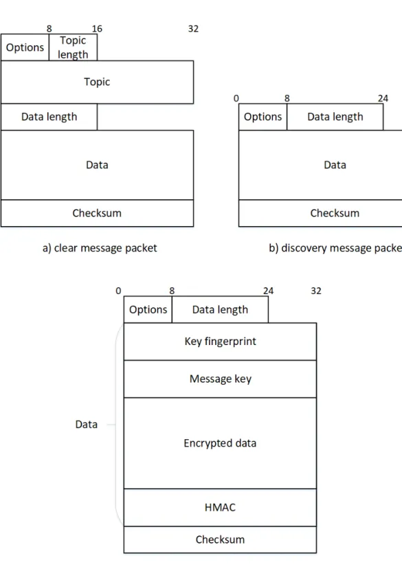
4.1.3. Data message
307 308
Figure4a represents a single and unencrypted data message in our solution. Every packet begins
309
with an options byte, divided in two parts. The first three most significant bits (MSB) compose the
310
version number of this packet and is all set to 0 for the version we present here. The other bits
311
are reserved and unused except for the two least significant bits (LSB) who represent flags used in
312
discovery and encrypted mode and have to be set to 0. These options are followed by the topic length
313
which can go from 1 to 255 characters encoded on a single byte. Any message without topic has to
314
be considered as an error and forget. Next come the topic with a variable length defined previously
315
followed by the data length encoded on two bytes (the protocol tolerate empty data packages) and
316
the data associated. Finally, a checksum is computed with the whole packet by using the CRC-32
317
algorithm already used in the Ethernet frame which is a fast and lightweight hash algorithm. It has
318
to be noted that the maximum size of one packet is limited by the theoretical limit of UDP which is
319
65,535 bytes. When a client receives a packet, the first operation he has to do with it is the checksum
320
validation. If this fails, the packet has to be dropped as the protocol does not have any mechanisms
321
to send the packet again. Otherwise, the packet can be split by using the different sizes and the data
322
and topic can be easily read.
323
4.1.4. Discovery message
324 325
A really interesting feature we have to provide is a mechanism to discover entities in the network.
326
To achieve this, each of them can register custom key-value pairs in addition to any readable (i.e.
327
allowing GET method) configuration values that will be exposed to any discovery request. Figure4b
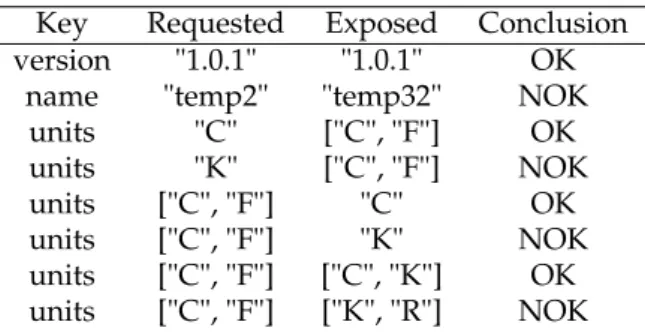
Table 4.An example of the discovery decision process Key Requested Exposed Conclusion version "1.0.1" "1.0.1" OK
name "temp2" "temp32" NOK units "C" ["C", "F"] OK units "K" ["C", "F"] NOK units ["C", "F"] "C" OK units ["C", "F"] "K" NOK units ["C", "F"] ["C", "K"] OK units ["C", "F"] ["K", "R"] NOK
represents a single discovery packet. As the data packet, the options come first. The only difference is
329
the LSB of this particular byte which is set to 1 representing a discovery packet. Next come the length
330
of the data containing the request, a simple key-value data structure represented in JSON format.
331
For security reasons, data has to be set in order to limit the number of answers. Consequently, any
332
discovery packets with a zero-length data have to be ignored and consider as an error. When the
333
frame is received, receivers will have to decide if they have to answer or not. To achieve this, they
334
check every key in the request if they do not have one of them they can drop the packet they must
335
not answer. Regarding the associated values, two cases are possible : either the key contains a single
336
value or an array of values. Consequently, four situations can occur depending on the combination of
337
two different data type on the receiver and the sender. Examples of each case are presented in Table
338
4. The first case shown here is when both requested and exposed are single value. In this case, the
339
two values have to be exactly the same as presented in the first two lines of the table. Next, come the
340
case where one has an array and the other a single value here, the single value has to be in the array
341
like in the lines 3 to 6 in the Table4. Finally, when both have arrays as values, at least one value in the
342
requested array has to be present in the exposed one.
343
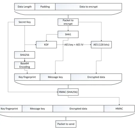
4.1.5. Encrypted data message
344 345
As we deal with sensitive information inside a smart environment, our protocol has to provide
346
an easy way to secure the communications. We adapt a well-known secure chat found in the Telegram
347
[36] application to achieve this goal.
348
The encryption process starts by adding random padding to the message. Indeed, Advanced
349
Encryption Standard (AES), the encryption algorithm we use, is a block cipher so our data have to
350
be a multiple of the block size Bs. The number of random bytes Ps we have to add is defined by
351
the formula1. We always add Bs bytes in order to always put some randomness in the original
352
message then, we add enough bytes to be a multiple of Bs (16 in the case of AES). In formula1we
353
use DataLength+2 because the last step in the packet preparation is the prepending of the data size
354
a two-byte long number.
355
Ps =Bs+ (Bs− (DataLength+2)%Bs) (1)
When the packet is ready to be encrypted, we create the message key used to generate the AES
356
key and IV by computing the SHA1 of the packet to encrypt. This hash is given to a Key Derivation
357
Function (KDF) with the Secret Key preconfigured by using the configuration channel. The KDF
358
presented in algorithm 1 is a sequence of different SHA1 hash and will result in two values, the
359
128-bit AES Key and AES IV used to encrypt the packet with AES. Next, in order to identify the secret
360
key used to encrypt, we compute a unique fingerprint of it by using the Base64 representation of the
361
key SHA256. Finally, the hash message authentication code (HMAC) is computed by using the secret
362
key with the SHA1 hashing algorithm.
Figure 5.The encryption process.
Data:secret_key[16], msg_key[20]
Result:aes_key[16], aes_iv[16]
sha1_a = sha1(msg_key + secret_key[0...3]);
sha1_b = sha1(secret_key[4...5] + msg_key + secret_key[6...7]); sha1_c = sha1(secret_key[8...11] + msg_key);
sha1_d = sha1(msg_key + secret_key[12...15]); aes_key = sha1_a[0...3] + sha1_b[0...7] + sha1_c[4...7]; aes_iv = sha1_a[12...15] + sha1_b[12...19] + sha1_d[0...3];
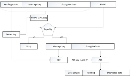
Figure 6.The decryption process.
In order to decrypt an encrypted packet (identified by a 1 at position 1 in the option byte of the
364
header) the receiver has to do some operations sum up in Figure6. The first task to accomplish is to
365
verify the HMAC to ensure the authentication and the integrity of the packet. To accomplish this, we
366
first have to retrieve the preconfigured secret key used to encrypt identified by its fingerprint. Next,
367
we can compute the HMAC of the packet (without the sender HMAC) and check for equality. If
368
the two hash message authentication codes are different, the packet must be dropped otherwise, the
369
decryption process can begin. First, we have to reconstruct the AES key and IV used to encrypt the
370
message by passing the preconfigured secret key and the message key received in the KDF algorithm
371
presented earlier. Next, we can use AES 128 algorithm in decrypt mode with the generated key and
372
IV to finally decrypt the whole message. The final step is to remove the padding bytes which can be
373
easily done with the message size store in the first two bytes.
374
4.2. Tests and discussion
375
In order to validate the proposed protocol, we have made three tests on it. The first one is about
376
bandwidth and try to maximize the number of messages per second exchanged to demonstrate the
377
speed of our protocol. The second one answers a question about the UDP protocol. Indeed, UDP does
378
not provide safety mechanisms about lost, corrupted or disordered network packet. Consequently we
379
decide to show the number of packets we did not receive because of this lack. Finally, we want to
380
demonstrate the fact that even with the same message and secret key, our encrypted packet is always
381
totally different in order to prevent semantic attack since our Initialization Vector is not randomly
382
generated. To accomplish that, we will compute a similarity measure between encrypted packets
383
containing the same message with the same encryption key. The hardware used in our tests was a
384
laptop (MSI GT62VR), a Raspberry Pi 3 and a Raspberry Pi Zero W. The first one was connected to a
385
Gigabit wireless router (LinkSys WRT1900AC) through its Gigabit wired and wireless (AC Wi-Fi) card
386
and the other ones over a simple Wi-Fi connection. Concerning the implementation of our solution,
387
we used C++ with the libraries Boost ASIO (for the network) and Crypto++ (for the encryption
388
algorithms).
389
In order to test the bandwidth capabilities of our protocol, we first generate 9 random messages
390
with different sizes from 16 bytes to 60 kibibytes (kiB). Then, we bound a listening process on the
391
wired network card on the laptop in order to monitor the packets transiting through the network
392
while we use wireless connections to send 20 000 packets for each different sizes with 10 000 encrypted
393
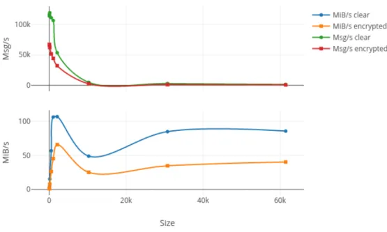
and another 10 000 not. Results from this test are summed up in Figures7to9where the upper plot
represents the messages per second (Msg/s) and the lower one the data rate in mebibytes per second
395
(MiB/s) transmitted by our protocol both depending on the message size. Figure7,8,9respectively
396
show the laptop, Raspberry Pi 3 and Raspberry Pi Zero W results. The first thing we can note is the
397
important drop in both data rates and message per second occurring for packet larger than 2kiB on
398
every platform and for both encrypted and non-encrypted messages. With respectively 10.9, 13.1, 3.8,
399
4.6, 2.2 and 2.78 times fewer messages sent depending on the platform and encryption, our solution
400
seems to present a limit concerning high-frequency large messages (greater than 1000 per second). We
401
investigate the reason for such a decreasing in performances and it seems to be fragmented Ethernet
402
packets that appear when the length of the transported data is greater than the maximum data size
403
of an Ethernet packet which is 1522 bytes. The second observation is pretty obvious and is the fact
404
that message rate and data rate decreased when using encryption. This is due to the computation
405
of different cryptographic algorithms like AES or SHA but we can say that for a packet under the
406
2kiB limit the encryption process does not impact too much our protocol. Finally, we can say that our
407
protocol does not overload the Raspberry Pi Zero W, the smallest platform, since both encrypted and
408
clear tests give nearly the same results in terms of data rates which can be explained by a fully used
409
network adapter.
410
Figure 7. Bandwidth results in terms of Msg/s and MiB/s for 10,000 send on the laptop of an increasing message size in both encrypted and clear mode
Figure 8.Bandwidth results in terms of Msg/s and MiB/s for 10,000 send on the Raspberry Pi 3 of an increasing message size in both encrypted and clear mode
Figure 9.Bandwidth results in terms of Msg/s and MiB/s for 10,000 send on the Raspberry Pi Zero W of an increasing message size in both encrypted and clear mode
UDP is a protocol without any reliability mechanisms. It means that packets can be lost or
411
corrupt and the protocol does not support any means to retrieve this packet unlike TCP. As our work
412
is based on UDP and does not provide such mechanisms either, we wanted to show and quantify
413
the risk of data loss. To do so, we create 10 000 messages of 1kiB composed by a two-bytes long
414
sequence number and some random padding. While the wired interface on the laptop monitor the
415
packet arrival (order, corruption using the embedded checksum or loss) the wireless connections
416
send 10 000 packets in order. The results of this test are summed up in Table5 where each line
417
represents a different platform (laptop, raspberry Pi 3 and raspberry Pi zero W) and the three columns
418
are respectively the number of lost packet, corrupted ones and finally the number of sequencing
419
problems. As we can see, on the same network, we did not lose or receive corrupted packets but we
420
had some problem in the sequence (2 for the laptop and Raspberry Pi 3 and 3 for the Raspberry Pi
421
Zero W). That means that over 10 000 messages only 2 or 3 arrive before the previous one a result that
422
tends to prove the relative reliability of our protocol even if we use UDP as our transport protocol.
423
Table 5.Number of lost, corrupted or misplaced packets over 10,000 send of a 1kiB message Sender Packets lost Packets corrupted Sequence problem
Laptop 0 0 2
Pi 3 0 0 2
Pi Zero W 0 0 3
The last test we did is a similarity test. Indeed, while we ensure the confidentiality of the data in
424
encrypted mode, we did not randomly generated our Initialization Vector (IV) for the AES encryption.
425
Instead, we use an algorithm (KDF described in algorithm1) to be able to compute the IV based on
426
information found in the encrypted packet and the secret key. And yet, the randomization of this IV
427
guarantees the semantic security of AES. Consequently we wanted to know if our algorithm using
428
random padding bytes is random enough to ensure a non-similarity between encrypted packets with
429
the same secret key and containing the same data. To validate this point, we compute the Euclidian
430
distance between 1000 secured packets containing the same 1kiB message of random data. The results
431
of this test are summed up in table6. In this last one, the first line represents the maximum distance
432
we can obtain by having one packet with all bytes set to 0 and the other 255 this maximum distance
433
will be used as a reference to compute the percentage of difference between packets. Next comes the
434
mean distance computed on all the packets, with a value of 3458.79, together with a maximum of
435
3775.54 and a minimum of 3175.23, we can say that our algorithm guarantee a relative non-similarity
436
between those packets. Finally, we report the mean difference percentage of 42.39% in the last line
437
of the results table. This means that for the exact same packet encrypted with our algorithm we
438
generate encrypted packets that are on average 42.39% different. Consequently, we can say that our
439
encryption process, even if it does not use a full random one, compute sufficiently different IV for the
440
same packet in order to protect it from semantic and similarity attacks.
441
Table 6.Distance between 1000 packets containing the same message of 1kiB on the same topic and encrypted with the same encryption key
Variable Value
Maximum theoretical distance 8160 Mean distance 3458.79 Maximum distance 3775.54 Minimum distance 3175.23 Mean difference percentage 42.39%
In conclusion, we can say that our tests were divided in three. The first one was to compute the
442
speed capabilities of our protocol. In this case the results demonstrate that for data under 2kiB we
assure a very high speed with nearly a thousand messages per second on the lightest platform we
444
executed the test on. Another conclusion that we made thanks to this test is the relative low-impact
445
of the encryption even on light platform. The second test was realized to ensure the reliability of
446
UDP multicast on a single network. Indeed, this communication protocol does not provide reliability
447
insurance mechanisms and we wanted to put a number on the risks inherent in its usage. With 0
448
packet lost or corrupted and a maximum of 3 order problems over 10 000 messages sent we can safely
449
say that even if we use UDP as our base communication protocol, our method seems to be reliable
450
enough for data streaming inside a Smart Home. Finally, the last test we executed was to compute
451
the similarity between secured packets containing the same message and encrypted with the exact
452
same secret key. Indeed as our Initialization Vector is computed instead of randomly generated we
453
had to prove that the semantic security of AES is guaranteed. Our results show that our algorithm to
454
derive the AES key and IV from the message itself and the secret pre-shard key is random enough to
455
an average of 42.39% difference between 1000 encrypted packets containing the same data.
456
5. Conclusions and future works
457
In this paper, we introduced a new distributed way to communicate between smart entities
458
distributed in an environment. Unlike MQTT or RabitMQ, well-known protocols, we don’t need
459
to have a centralized broker instance and unlike ZMQ, a well-known framework to implement
460
messaging protocols, we don’t rely on POSIX sockets which are hard to embed on tiny devices
461
without a Linux or Windows operating system. Our protocol, like FTP, relies on two channels. The
462
first one is for the configuration of every entity in the network and is based on COAP, a well-known
463
protocol in the field of the Internet of Thing, for its reliability. The other one is a data channel, based
464
on multicast messages with a protocol entirely define in this paper. This last one permits to send
465
discovery requests to the network as well as messages encrypted or not. For the encrypted way, we
466
adapt the Telegram protocol a well-known secure instant messaging protocol in order to work on tiny
467
devices and provide an easy authentication with a HMAC.
468
In this paper, we realized three different tests to ensure our capabilities in terms of speed,
469
reliability and security. In the light of the results, we can say that for data under 2kiB we ensure
470
a very high speed with nearly a thousand messages per second on the lightest platform we executed
471
the test on. Moreover, with no packet lost or corrupted and a maximum of 3 order problems over
472
10 000 messages sent we can safely say that our method seems reliable enough for data streaming.
473
Finally, our results show that our algorithm to derive the AES key and IV from the message itself and
474
the secret pre-shard key is random enough to generate an average of 42.39% difference between 1000
475
encrypted packets containing the same data ensuring the security against semantic attacks.
476
Ultimately, we can say that our protocol with its two channels allows to make a difference
477
between configuration values which need a high reliability but won’t be changing every millisecond
478
and data values or streaming which need higher data rates but less reliability. Moreover, our protocol
479
support a native encryption mode which provides security for sensitive information we can easily
480
find in a Smart Home. In addition, we designed our innovation to be both brokerless, which is
481
the main difference between many existing messaging protocol, and easily portable as it only relies
482
on UDP, a communication protocol found in every network applications. Lastly, as a future work,
483
we want to realize more tests including tests on embedded environment, like a Real Time OS on a
484
microcontroller and tests with a lot more entities in the network.
485
Abbreviations
486
The following abbreviations are used in this manuscript:
487
AES: Advanced Encryption Standard
488
AI : Artificial Intelligence
489
Amb. I: Ambiant Intelligence
AMQP: Advanced Message Queuing Protocol
491
BLE: Bluetooth Low-Energy
492
CoAP : Constrained Application Protocol
493
CRC: Cyclic Redundancy Check
494
EEPROM : Electrically Erasable Programmable Read-Only Memory
495
GHz: gigahertz
496
HMAC : keyed-Hash Message Authentication Code
497
HTTP: Hypertext Transfer Protocol
498
IEEE: Institute of Electrical and Electronics Engineers
499
IoT: Internet of Things
500
IV: Initialization Vector
501
KDF : Key Derivation Function
502
LNCF: Lght Node Communication Framework
503
LIARA: Laboratoire d’Intelligence Ambiante pour la Reconnaissance d’Activités
504
LSB : Least Significant Bit
505
LWT: Last Will Testament
506 kB: kilobyte 507 kiB: kibibyte 508 kiB/s: kibibyte/second 509 MHz: megahertz 510 MiB: mebibyte 511 MiB/s: mebibyte/second 512
MSB : Most Significant Bit
513
Msg/s: messages/seconds
514
OSGI: Open Service Gateway Initiative
515
RAM: Random Access Memory
516
RTOS : Real Time Operating System
517
SDSH: Software Defined Smart Home
518
SHA: Secure Hash Algorithms
519
SoC: System on Chip
520
SPoF: Single Point of Failure
521
UDP: User Datagram Protocol
522
XMPP : eXtensible Messaging and Presence Protocol
523
ZMQ : ZeroMQ
524 525
Author Contributions:All the authors contributed equally to this work.
526
Conflicts of Interest:The authors declare no conflict of interest.
527
Bibliography
528
1. Cook, D.J.; Crandall, A.S.; Thomas, B.L.; C., K.N. CASAS: A Smart Home in a Box 2012. 100, 130–134.
529
2. Ghayvat, H.; Mukhopadhyay, S.; Gui, X.; Suryadevara, N. WSN- and IOT-based smart homes and their
530
extension to smart buildings. Sensors (Switzerland) 2015, 15, 10350–10379.
531
3. King, J.; Jansen, E. The Gator Tech Smart House. Computer 2005, 38, 50–60.
532
4. Patterson, D.J.; Liao, L.; Fox, D.; Kautz, H. Inferring High-Level Behavior from Low-Level Sensors.
533
International Conference on Ubiquitous Computing, 2003.
534
5. Augusto, J.C.; Nugent, C.D. Designing smart homes: the role of artificial intelligence; Vol. 4008, Springer, 2006.
535
6. Roy, P.C.; Bouchard, B.; Bouzouane, A.; Giroux, S. Ambient Activity Recognition in Smart Environments
536
for Cognitive Assistance. International Journal of Robotics Applications and Technologies 2013, 1, 29–56.
537
7. United Nations.; Department of Economic and Social Affairs.; Population Division. World Population
538
Ageing 2015. Technical report, 2015.
8. Hunkeler, U.; Truong, H. MQTT-S—A publish/subscribe protocol for Wireless Sensor Networks. systems
540
software and . . . 2008.
541
9. Videla, A.; Williams, J. RabbitMQ in action: distributed messaging for everyone 2012.
542
10. Zeromq, 2016.
543
11. Cook, D.J.; Youngblood, M.; Heierman, E.; Gopalratnam, K.; Rao, S.; Litvin, A.; Khawaja, F. MavHome:
544
an agent-based smart home. Proceedings of the First IEEE International Conference on Pervasive Computing
545
and Communications, 2003. (PerCom 2003). 2003, pp. 521–524.
546
12. Giroux, S.; Leblanc, T.; Bouzouane, A.; Bouchard, B.; Pigot, H.; Bauchet, J. The Praxis of Cognitive
547
Assistance in Smart Homes. BMI Book 2009, pp. 183–211.
548
13. Xu, K.; Wang, X.; Wei, W.; Song, H.; Mao, B. Toward software defined smart home. IEEE Communications
549
Magazine 2016, 54, 116–122.
550
14. Patel, S.M.; Kanawade, S.Y. Internet of Things Based Smart Home with Intel Edison. Proceedings of
551
International Conference on Communication and Networks. Springer, 2017, pp. 385–392.
552
15. Bouchard, K.; Bouchard, B.; Bouzouane, A. Guidelines to Efficient Smart Home Design for Rapid AI
553
Prototyping: A Case Study. PETRA 2012.
554
16. Advantech. Automation Controllers & I/Os, 2016.
555
17. Dell. Dell PowerEdge Rack Servers, 2016.
556
18. OSGiTMAlliance – The Dynamic Module System for Java, 2016.
557
19. Drumea, A.; Popescu, C.; Svasta, P. GSM solutions for low cost embedded systems for industrial control.
558
28th International Spring Seminar on Electronics Technology: Meeting the Challenges of Electronics
559
Technology Progress, 2005. IEEE, 2005, pp. 240–244.
560
20. Li, C.S.; Liao, W. Software defined networks. IEEE Communications Magazine 2013, 51, 113–113.
561
21. McKeown, N.; Anderson, T.; Balakrishnan, H.; Parulkar, G.; Peterson, L.; Rexford, J.; Shenker, S.; Turner, J.
562
OpenFlow: enabling innovation in campus networks. ACM SIGCOMM Computer Communication Review
563
2008, 38, 69–74.
564
22. Chu-Sing, Y.; Mon-Yen, L. Realizing Fault Resilience in Web-Server Cluster. ACM/IEEE SC 2000
565
Conference (SC’00). IEEE, 2000, pp. 21–21.
566
23. Lu, F.; Parkin, S.; Morgan, G. Load balancing for massively multiplayer online games. Proceedings of
567
5th ACM SIGCOMM workshop on Network and system support for games - NetGames ’06; ACM Press:
568
New York, New York, USA, 2006; p. 1.
569
24. Mon-Yen, L.; Chu-Sing, Y. Constructing zero-loss Web services. Proceedings IEEE INFOCOM 2001.
570
Conference on Computer Communications. Twentieth Annual Joint Conference of the IEEE Computer
571
and Communications Society (Cat. No.01CH37213). IEEE, 2001, Vol. 3, pp. 1781–1790.
572
25. Schroeder, T.; Goddard, S.; Ramamurthy, B. Scalable Web server clustering technologies. IEEE Network
573
2000, 14, 38–45.
574
26. Atzori, L.; Iera, A.; Morabito, G. The internet of things: A survey. Computer networks 2010.
575
27. Liu, B.; Cao, S.G.; He, W. Distributed data mining for e-business. Information Technology and Management
576
2011, 12, 67–79.
577
28. Chen, M.; Mao, S.; Liu, Y. Big data: A survey. Mobile Networks and Applications 2014, 19, 171–209.
578
29. Hey, A.; Tansley, S.; Tolle, K. The fourth paradigm: data-intensive scientific discovery 2009.
579
30. IEEE Standard for a Smart Transducer Interface for Sensors and Actuators, 1998.
580
31. Lewis, F. Wireless sensor networks. In Smart Environments: Technology , Protocols, and Applications; 2005;
581
chapter 2.
582
32. Martin, G.; Zurawski, R.; Philips, C. Trends in embedded systems Opportunities and challenges for
583
System-on-Chip and Networked Embedded Systems technologies in industrial automation. ABB Review
584
2006, 2.
585
33. Hintjens, P. ZeroMQ: messaging for many applications; 2013.
586
34. Postel, J. User Datagram Protocol. RFC 1980.
587
35. Shelby, Z.; Hartke, K.; Bormann, C. The constrained application protocol (CoAP) 2014.
588
36. Telegram. Telegram Protocol, 2013.
589
c
2017 by the authors. Submitted to Sensors for possible open access publication under the terms and conditions
590
of the Creative Commons Attribution license (http://creativecommons.org/licenses/by/4.0/)