HAL Id: hal-02954399
https://hal-mines-albi.archives-ouvertes.fr/hal-02954399
Submitted on 8 Oct 2020HAL is a multi-disciplinary open access archive for the deposit and dissemination of sci-entific research documents, whether they are pub-lished or not. The documents may come from teaching and research institutions in France or abroad, or from public or private research centers.
L’archive ouverte pluridisciplinaire HAL, est destinée au dépôt et à la diffusion de documents scientifiques de niveau recherche, publiés ou non, émanant des établissements d’enseignement et de recherche français ou étrangers, des laboratoires publics ou privés.
Eco-friendly foam biocomposites based on cellulose
extracted from date palm leaves and low-density
polyethylene
Hanna Maria, Adriaan, Luyt, Anton Popelka, Ange Nzihou, Vladimir
Valentinovich Egorov, Igor Krupa, Mariam Al-Ali Al-Maadeed, Sabu Thomas
To cite this version:
Hanna Maria, Adriaan, Luyt, Anton Popelka, Ange Nzihou, Vladimir Valentinovich Egorov, et al.. Eco-friendly foam biocomposites based on cellulose extracted from date palm leaves and low-density polyethylene. Functional Composites and Structures, 2020, 2 (4), pp.1-13. �10.1088/2631-6331/abbb10�. �hal-02954399�
Eco-friendly foam biocomposites based on cellulose extracted
from date palm leaves and low-density polyethylene
Hanna J Maria1,2Adriaan Stephanus Luyt,1Anton Popelka ,1, Ange NZHIOU3 Vladimir
Valentinovich Egorov 4,Igor Krupa1, Mariam A S Al-Ali Al-Maadeed1* Sabu Th mas,1,5
1School of Energy Materials, International and Inter-University Centre for Nanoscience nd
Nanotechnology, Mahatma Gandhi University, Kottayam, Kerala, Ind
2Centre for Advanced Materials, Qatar University, State of Qat r 3RAPSODEE Research Centre - CNRS, IMT Mines Albi, France
4Russian Academy of Sciences, Photochemistry Center, Moscow 119421, R ssian Federation 5School of Chemical Sciences, Mahatma Gandhi University, Kottayam, Kerala, India
m.alali@qu.edu.qa, sabuthomas@mgu ac.in
Abstract: The design of composite materials using environmentally compatible materials
and adopting sustainable preparation techniques are highly required for a better environment. The present study is a step towards developing an environment friendly alternative to foam-based composites. The aim of the study is to know the effect of natural fibers from date palm on the property of foam biocomposites. We adopted an env ronment friendly method of compatibilization between the polymer and the fibers for tter reinforcement. The compatibility was done by environment-friendly physical modification using plasma treatment. Plasma treatment provides surface modification a d this is an economical solution for further processing. In fact three types of interfaces have been created: 1) by the addition of maleic anhydride, 2) use of plasma trea LDPE, 3) the combination of maleic anhydride and plasma. The overall perform nce was the best by the use of plasma treatment alone. The effect was carefully nalyzed based on the morphological, mechanical and thermal studies. Finally, morphology-property correlation was established
1. Introduction :
The awareness to protect our environment ha brought out an overwhelming change in the research field in developing products based on env nment friendly polymer materials [1-4].The art of making polymer comp site d on the requirement of the industry has brought out novel materials with excellent properties. Perceptively designed polymer composites possess unique physi al, mechanical and thermal properties which are governed by the polymer matrix. Other major pa meters that can change the final properties are the fillers and additives. Polymer foam mposites are lightweight materials with many attractive properties such as low density, impact damping, thermal insulation, flexibility etc. Polymer foams have wide ra ge of applications in offshore exploration of oil and gas, in electromagnetic shieldi g thermal and acoustic insulation [5]. The properties of polymer foams not only depend on the intrinsic properties of the polymer, but also on the foam morphology, such as cell density, cell size and size distribution[6].It is important to improve the properties of the e composite foams, which is still not yet explored completely. Addition of fibers long or short) to composite foams provides modified microstructure with improved strength and damage tolerance. Fillers in micro or nano level can be used to prepare polymer nanocomposite for foams. One of the reasons for adding fillers while synthesising polymeric foam nanocomposites is to improve the strength of the foam without affecting its light weigh . Recent research focuses on adding micro and nanofillers so that they can act as
nucleation sites to decrease cell size along with reinforcing the composite. Lee et al.[7] have studied the foaming behaviours of wood fiber/high density polyethylene (HDPE) composites with small amounts of nanoclay. The results suggested that the addition of nanoclay improved the cell morphology of the wood fiber/HDPE composite foams as its content and degree of dispersion increased. The research in foam industry mainly aims at producing n environment friendly foam product which uses natural resources and non-haza dous materials. It is expected that these foams during processing can impart excellent prop rties to the final product. Natural fiber based biodegradable polymer foam composites are yet to be produced in high quantities in foam industry. Cellulose fibers have been foreseen to be used as the potential fillers in foam composites. There are many concerns relati g to environment protection which leads to the development of biocomposites through environment friendly methods. The greater usage of natural fibers and the environm tal friendly methods for foam preparation are a viable alternative to produce environmental friendly polymeric foams with comparable properties. Although the uses of natural fibe s have successfully been used to prepare good composite materials with excellent prope ties, they are not widely used in designing foam materials. However, recently the use of n tural fibers in foam composite also gained recognition due to the wide scope of product de lopment using natural resources as well as property enhancement. Andre et al. [8] h e studied new applications for foam composites of polyurethane and recyc ed b Rubber was supported in a polyurethane matrix generating two new products of distinct characteristics and properties. [9-13]. Usually
in polymer composites the foam g agents are blended with the polymer or added directly into the hopper and from there down th ough the barrel to the mold. Thermal decomposition of chemical reaction of the ma i l may be either endothermic (heat absorbing) or exothermic (heat generating). Endothermic foaming agents primarily produce CO2 while
exothermic mostly ge rate N2. The blowing agents like chlorofluorocarbons, (CFC's)
hydrochlorofluoroca bo s (HCFC's) hydrofluorocarbons (HFC s)are mostly not preferred because of their neg tive environmental impact on the ozone layer. These have high global warming potential although these are ideal blowing agents. Liquid CO2 are also used as a
blowing agent ecau e it does not have the same environmental issues as CFC's and HCFC's. It has a low global warming potential and is inexpensive. However endothermic chemical blowing ag s such as mixtures of sodium bicarbonate and citric acid are gaining in popularity for foaming thermoplastics because of properties such as: fast degassing times, improved cell structure, and endothermic decomposition and is also environment friendly.
The present study is a step toward developing a comparatively environment friendly alternative to foam-based composites usually prepared by using foaming agents like CFC's HCFC's and HFC's which are harmful to environment. For environmentally friendly blowing agents the by-products are not harmful. The blowing agents used wer citric acid and sodium bicarbonate The aims of the study are; (1) to have a de p understanding of the effect of natural fibers from date palm trees on foam biocomp ite, (2)to adopt an environment friendly method of compatibilization between the polymer and the fibers for better reinforcement. Considering the use of cellulose from agro waste and the
introduction of eco-friendly blowing agents, we have adopted a process which is environmentally friendly. Plasma treatment provides surface treatme and it is an
economical solution for further processing. Plasma treated LDPE urface can modify the interfacial properties and thus improve ultimate composite chara teristics. The method is economic also as the materials used for the preparation is not c stly[14,15,16]. A lot studies are reported that explains the significance of plasma treatmen on polymers which shows the improved adhesion to natural fibers[17,18,19,20]
The current study employs low-density po yethylene (LDPE) as a resilient and non-brittle material. LDPE offers several advantages such s lightweight, low cost, flexibility (low modulus), toughness, chemical resistance and ease of seal ability etc[21]. An environment-friendly procedure for compatibility between date palm fibers and LDPE has been adopted by plasma treatment (physical modification) of the LDPE surface.. The work will pave way in the value addition of date palm l ves which is widely available especially in the middle east.
2. Experimental
2.1. Materials and methods
The base polymer which was used for the preparation of foam composite was LDPE (grade Lotrène ® FD0274) supplied by QAPCO with melt flow index 2.4g/10 min. The blowing agents used were citri acid and sodium bicarbonate supplied by Sigma Aldrich. The date palm leaves were collected locally from the Qatar University gardens.
2.1.1. Preparation of microfibers from date palm leaves
The date palm leaves were washed well with water to remove the dirt and other pollutants. It was dried and was cut into small pieces of about 1cm length. The leaves were then dried in an ov for overnight. It was then ground into fine fibers using a blender. The powder was separated into 40µm, 60 µm and100 µm particles using a micro sieve shaker. 45 g of
100µm powder was taken and was treated with 2%NaOH for 3 hrs at 90℃ to remove the hemicellulose, lignin, and other substances in small amount like pectin bounded to the cellulose. The fibers were then washed with water till it became neutral.
Fiber-OH +NaOH Fiber O Na+H2O
The alkali treated fibers were then bleached with an equal volume of sodium hypochlori e (1:3) and buffer solution (NaOH and acetic acid).The process was repeated 5times to remove as lignin content, and the white fibers obtained after the bleaching was washed with distilled water several times. Finally, the fibers were dried for analysis.(Scheme 1)
Scheme 1: The microfibers prepared from date palm leaves
2.1.2. Preparation of polymer foam composite 2.1.2.1. Preparation of masterbatc
10g of the polymer was melted mixed in xylene and was mixed with fiber and maleic anhydride. It was then cast and xylene was removed by placing it in the oven at a temperature of 55⁰C for one week, fter th it was dried and powdered.
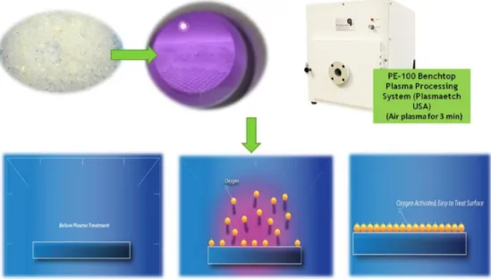
2.1.2.2. Preparation of pl sma modified LDPE(PLDPE) as a compatibilizer.
LDPE was treated with air plasma under the following condition: The LDPE pellets were put in the chamber and subjected to air plasma treatment. Prior to the plasma treatment, the vacuum in the chamber was maintained to 0.2 mtorr. After the pressure became stable, the plasma treatment was carried out by a radio frequency power generator operating at 80 W for 3 minutes The plasma modification was done using PE-100 Benchtop Plasma System (Plasma Etch, Inc Drive Carson City, USA) in a 12” X 12” X 12” Welded Aluminum Vacuu Chamber. (Scheme 2). The plasma modified LDPE is coded as PLDPE.
Scheme 2: Plasma modification of LDPE
2.1.2.3. Preparation of LDPE foam composites
LDPE was mixed with 8g (i.e. 4phr) of endothermic b wing agent(a mixture of sodium
bicarbonate and citric acid) along with the repared master batch. The mixture was then
extruded using a twin screw extruder(Twin Extrude (KETSE 20/40D - Brabender)with the temperature of zone 1,2,3,4 and 5 as 1 0, 70 180,180and 1900C. The extruded composite in
the sheet foam was then analyzed.
The different foam compositespr pared and their code is given in Table 1. The explanations for the codes are as follows. G stands for gum compound without fiber, F stands for fiber filled composite, B stands for blo ing agent, M stands for maleic anhydride, P stands for plasma modified LDPE and the digits 3 and 5 indicate the amount of fiber in the composite. For example, FMPB5 dicates a fiber filled composite having 5 phr fiber containing maleic anhydride, plasma modified LDPE and blowing agent.
Table 1 :The differ nt foam composites prepared and their code CODE Composi ion
GB LDPE + Blowing Agent
FB3 LDPE+ Blowing Agent+3phr Fiber FB5 LDPE+ Blowing Agent+5phr Fiber
GMB LDPE+ Maleic Anhydride + Blowing Agent
FMB5 LDPE+ Maleic anhydride + Blowing Agent+ 5phr Fiber GMPB LDPE+ PLDPE+ Maleic anhydride + Blowing Agent
FMPB3 LDPE+ PLDPE+ Maleic anhydride + Blowing Agent+3phr Fiber FMPB5 LDPE+ PLDPE+ Maleic anhydride + Blowing Agent+5phr Fiber FPB5 LDPE+ PLDPE+ Blowing Agent+5phr Fiber
2.2. Characterisation techniques 2.2.1. Mechanical properties
The tensile properties of the films were measured using the RSA-G2 (TA Instruments, USA) according to ASTM D638-5 at 25°C and at across head speed of 10 mm/mi Dumbbell-shaped specimens were cut with a dimension of 65 mm x10 mm x3 mm. Five spe imens of each sample were tested; the tensile strength, elongation at break and Young’s modulus we e calculated as an average of five measurements.
2.2.2. Scanning electron microscopy
Nova Nano SEM field emission Scanning electron microscopy with an accelerating voltage of 5.0 kV and Joel Benchtop SEM- JCM 6000 with an accelerating oltage of 10kV was used. The samples were cryocutin liquid nitrogen and the surface w s plasma treated to remove the impurities.
2.2.3. Fourier transform infrared spectroscopy (FT R)
The FT-IR spectra of the films were measured using a Perkin Elmer Spectrum 100. The Fourier-transform infrared (FTIR) spectroscopic analysis of the samples was done from 400 to 4000 cm-1 in a Perkin Elmer Spectrum 400 FTIR with an ATR detector at a resolution of
4cm-1.
2.2.4. Differential scanning calorimetry
DSC analyses were performed on a Perkin Elmer DSC4000 differential scanning calorimeter. The samples were scanned in two cycles at a heating rate of 10⁰C/min from 40 to 140⁰C in nitrogen atmosphere.
2.2.5. Thermogravime ric nalysis.
Thermal gravimetri analysis (TGA) was done using a Perkin Elmer Pyris 6 TGA in a controlled atmosphere of itrogen, with scan range from 35° to 800° at a constant heating rate of 10 °C/m n an continuous nitrogen flow.
3. Results and Discussion
3.1Ch racterisation of micro-fiber 3.1.1Scann ng electron microscopy
Figure 1(a-b). SEM images of the a) raw fibers. and (b & c) bleached fiber.
The comparison between the treated and untreated fibers hown in Figure 1 (a-b)shows the structural differences affected by bleaching. The arrang ment of cellulose fibers within the matrix of lignin is clearly seen in this pic re. Figure.1a and b show defibrillation by dissolving the lignin that gets depolymerized. Bleac ed fiber shows a thickness in the range of 5–10µm. Each elementary fiber (figur 1 &d) shows a compact structure showing aligned fibers. The analysis shows that microfiber manufacturing using the above-mentioned method was successful. However, the fig re shows the presence of some compacted structure which can be due to the presence of residual lignin content.
3.1.2 Fourier transform infrared pectroscopy.
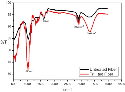
The FTIR spectra of raw f ber and alkali treated fiber are presented in Figure.2.which shows a change in the spectrum Conside ble changes were noticed in alkali treated fibers and are also supported by the SEM image It is reported that alkali treatment reduces hydrogen bonding by reacting with sodium hydrox de which results in an increase in -OH concentration which is evident from the increased inten it of the peak between 3300 and 3500 cm-1 bands as compared to the raw
fibers and this orresponds to the stretching of hydroxyl (O–H) groups in cellulose. The peak at 1600 cm-1 is rela ed to he absorbed water. The peak appearing around 1508 cm-1 is due to the
CH2 stretching from cellulose. The peak around 1236 cm-1 is considered due to C =O stretching of
acetyl in lignin which disappeared after treatment. The peak at around 1072 cm-1 is assigned to C-O
deformation in secondary alcohol and aliphatic ether. The peaks around 1515 cm-1 and 1240 cm-1 seen
in untreated fiber disappear after alkalization. The disappearance of the peak around 1515 cm -1 indic tes that the non-cellulose such as pectin, and fats are removed during the alkalization. The
disappearance of the peak around 1240 cm-1 after alkalization indicated that the removal of
hemicelluloses[22,23,24]
Figure 2.FTIR spectra of raw fiber a d alka i treated fiber 3.2 Characterisation of foam composites
3.2.1 Effect of filler loading 3.2.1.1 Morphological Analysis
Figure 3 shows the SEM analysis of foam composites with different fiber loading and compatibilizers. The figure shows that adding 5phr of fiber without any compatibilizer, increases in the number of cells dramatically. It can be observed from Figure 3a and b that on adding fibers, the cell size of the foam decreases. Foamed plastics exhibit reduced apparent densities due to the presence of numerous cells dispersed throughout the mass of the polymer. Foamed samples of all composites fiber show cells with finer average sizes in comparison to those of virgin LDPE.
Figure 3 c, d, e&f shows respectively the SEM micrographs of the 5 phr fiber reinforced foam composites with PE-g-. MA as the compatibilizers, hybrid compatibilizer of PE-g-. MA & plasma mod fied LDPE and with plasma modified LDPE (PLDPE) alone. The micrographs show that for the foam composites the addition of compatibilizer causes a change in the sh pe of the cells. However, cell density is found to decrease for compatibilized foam composites and the addition of the compatibilizers reinforces the foams which are confir ed by the mechanical property data.
500 1000 1500 2000 2500 3000 500 4000 4500 70 75 80 85 90 95 100 cm-1 Untreated Fiber Tr ted Fiber 3340cm1 1602cm1 2920cm-1 1041cm-1 %T
The size distribution of the pores for each sample was found by measuring the area using ImageJ software and is plotted in figure 3g.The comparatively smaller pore size was found for the composite when maleic anhydride alone was used as the compatibilizer. Howev r for all the composite the pore size was found to be reduced compared to the sample withou natural fiber. The mechanical properties of foam depend on the cell structure and cell distribution of foam. [25] However, for plasma modification alone, the cell shape seems t be the same although the mechanical properties were improved by plasma modificati n alone showing an improvement in the interfacial adhesion.
0 2 4 6 8 10 12 14 GB FB FMB5 FMPB5 FPB5 N o :o f co u n ts
Pore diameter (µm) distribution in different foam composites
0.14-0.20 0.06-0.10 0.001-0.02 0.10-0.14 0.02-0.06
Figure 3.1.SEM images of the foam composites a) GB without any fiber b) FB5 with 5phr micro fiber c)FMB3
with 3phr fiber and PE-g-. MA as compatibilizer d) FMPB3 with 3phr fiber and with hybrid compatibilizers
(PE-g-. MA and PLDPE) e) FMPB5 with 5phr fiber with hybrid compatibilizers(PE-g- MA and PLDPE) f) FPB with 5phr fiber and PLDPE g)The pore size distribution in each compositi n
3.2.1.3 Mechanical properties
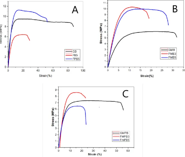
Figure 4A shows the stress-strain behaviour of the foam composites without fi ler (GB 5) with 5 phr microfiber alone (FB5), and with 5 phr micro fiber with PLDPE(FPB5). It is reported that the mechanical behaviour of polymer foams are dependent on the density, size, and shape of the cells and of the nature of the material,[26] The value shows that for the foam composite with plasma modified LDPE, the tensile strength was impr ved showing the better adhesion of fiber and polymer. The decrease in a number of cells in the case of plasma modified composite is also a reason for its influence o the ten ile strength. The interaction between the fiber and the polymer in the case of PE g-. MA incorporated foam composites results in the deformation of cells. Figure 4B shows the stress-strain behaviour of the foam composites with PE-g-MA as the compatibilizer without filler (GB 5) with 3 phr microfiber (FMB3), with 5 phr micro fiber (FMB5). Compared to neat foam composite, it can be observed from the stress-strain graph of the 3 and 5 phr fiber (with PE-g-. MA as the compatibilizer) that fiber incorporation could reinforce the foam composite to a good extent. The value of tensile strength is alm st doubled with a higher toughness for the5phr sample. Figure 4C shows the stress-strain behaviour of the foam composites with both PE-g-MA and plasma modified LDPE as the compatibilizer without filler (GMPB 5) with 3 phr microfiber (FMPB3), with 5 phr micro fiber (FMPB5). For both PE-g-MA and plasma modified LDPE incorporated foam composites, it is observed that the presence of both PE-g-MA and plasma modified LDPE have eff cted better reinforcement at 3 phr fiber loading. However, the toughness of both composites was lower than neat foam composites. This is due to the availability of interaction s tes which is explained later in each paper. An addition of more compatbilis r can fect in more property and this can be a scope for future studies which can be done y varying the compatbilizer concentration. The increase in a number of cells as observed from the morphological data (SEM) for the hybrid compatibilizer incorporated foam composites agrees with this.The incorporation of 5phr fiber shows better toughness.The increase of the maximum strength and the modulus due to the addition of compatiblizers
was due to an improvement in the mechanical adhesion that is promoted by the generation of greater surface area and roughness on the fiber as a result of the plasma treatment, the increase in the compatibility between the fiber and the matrix which decreased the fibres’ polarity,the formation of more bonds with the hydroxyl groups (OH) of the fiber and th organofunctional group with the polymer. An explanation of this is given later in the pape
Figure 4. A)Stress-strain graph of the foam composites with different fiber loading A)without any compatibilizer B) with PE g-. MA compatibilizer C) with hybrid compatibilizers (PE-g-. MA and PLDPE)
3.2.1.2 Differential s anning calorimetry(DSC)
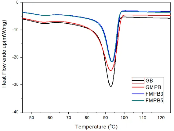
The DSC thermogram of th foam composite with various loading is given in figure 5.LDPE contains both alline and amorphous regions. The crystalline region consists of spherulites where the polymeric chains form an organized structure.27 The short branches in
LDPE lead to the formation of amorphous regions. From the DSC analyses during heating it is possible o determine the melting point, level of crystallinity and the presence of different phases in semi-crystalline polymers. The figure presents exothermal curves of foam
composites at different cooling rates. It could be observed that incorporation of fibers makes crystallization peak temperature (Tc) move slightly to higher temperature compared to neat foam composites, indicating some nucleation effect of fibers. The increase in crystallization temperature associated with the addition of micro and nano fillers in semi-crystallin polymers has been extensively reported (ref). The change confirms that fibers affect the phase formation in LDPE crystallization and shows that it affects the crystalliz tion behaviour too. The level of crystallinity of PE was enhanced with the incorpo ation of fibers. Moreover the nucleating effect is stronger for compatiblized system where parti les are better dispersed than for uncompatilized system where the dispersion of the fibers was poorer.
Figure 5. DSC thermogram f images of the foam composites -GB without fiber, GMBP foam composite without fibe , MPB3 with 3phr fiber and hybrid compatibilizers(PE-g-. MA and PLDPE), FMPB5 with 5phr fiber and hybrid compatibilizers(PE-g-. MA and PLDPE)
3.2.1.4 Thermogravimetri analysis (TGA)
Thermograms of ifferent foam composites are shown in figure 6. It is evident from the figure that the thermal decomposition of plasma modified foam composite with 5 phr fiber loading is comparatively higher showing more number of fiber polymer interactions and good adhesion between fiber and the polymer when PLDPE is added. This increased thermal tability indicates that the incorporation of the fibers into the material introduces more
number of nucleation points that increase the crystallinity of the polymer, and, which then results in improved thermal properties. However, the presence of fibers in the foam
composite with PE-g-.MA is not showing any increase thermal stability. This difference can be described to be due to the nature of the interaction between fiber and LDPE on varying th nature of compatibilizer which will be discussed in the next section.
Figure 6. TGA curve of the foam composites
Pl correct the Y axis of the figure 6, 2 times percent appeared.
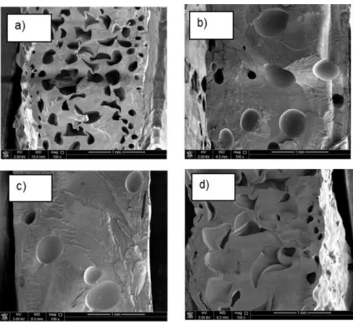
3.2.2 Effect of plasma modifi ions and its hybrid effect
The morphological, thermal mechanical and thermo mechanical analysis of the foam composites with nd without fibers and different compatibilization methods show that compared to oth foam composites, the plasma-treated LDPE based foam composite could improve all the properties. The morphological interpretation of the SEM images showed more cells in the case of foam composites with no compatibilizer.However there was a noticeable hange in the cell shape upon adding PE-g-. MA. Although the cell density values were comparatively decreased for the foam composite with PLDPE, the composite showed excellen reinforcement with appreciable cell density. The difference in the shape of the cells comp ed with PE-g-. MA can be due to the difference in the nature of the interaction. As a
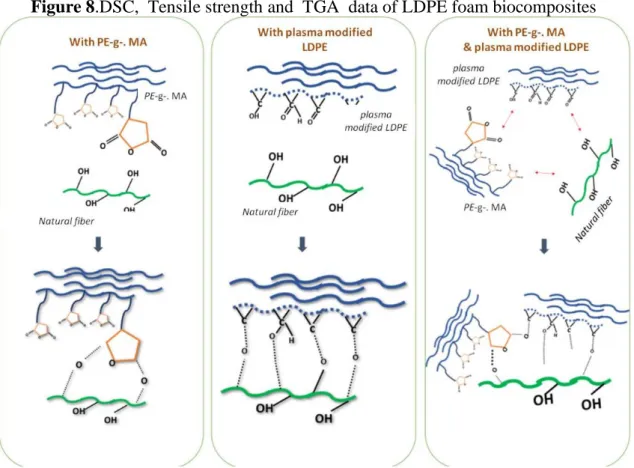
result of the superior compatibilization process arising from the plasma surface treatment, the LDPE matrix is well bonded to the fiber surface. This infact caused the deformation of the cells. The thermal properties showed comparatively more thermal stability for the foam composite with PLDPE (Fig 8a).The mechanical property (Fig 8b)also could support superio reinforcement when P LDPE was used. Both the tensile strength and toughness were improved. This improvement in PLDPE incorporated foam composites is supported by the well-known fact that the plasma treatment of the polymer surface results in the cr tion of new reactive sites on the polymer surface and can produce a variety of atomic functional groups, like carbonyl, carboxyl, and ester groups etc at the surface. Usually plasma treatment results in two simultaneous processes, one which increases the surface ughness by the process of etching of the polymer surface and other the formation of unct onal groups at the polymers surface by the interaction between the active species from the plasma and the surface atom .Such a modification for polymer is favourable for subsequent grafting on account of increased surface area. Thus the presence of both th surface roughness and that of the polar group on the LDPE must have caused superior int raction with the natural fiber and this must have thereby increased the adhesion between th two. However, on comparing the maleic anhydride grafted PE and the PLDPE foam mposites the improvement is quite higher for PLDPE foam composites and this can be c rified by the fact that, while for maleic anhydride grafted PE, the two carbonyl g p n each of it causes an interaction with the hydroxyl group of cellulose as represented (scheme 1 )in the case of PLDPE foam composites. In other words, more number of polar group on the surface of the LDPE causes more sites for interaction and thereby using an improvement in the overall properties. In the case of hybrid compatibilizer, th umber of sites for the interaction is reduced because of the additional possibility of interaction between maleic anhydride and PLDPE[ 28, 29 ]as represented in schemat c 1,which causes a reduction in the number of interaction sites with the natural fiber.
Figure 7. SEM images of 5phr fiber a) FB5-without any comp tibilizer – b) FMB5-with 5phr fiber and maleic anhydride as compatibilizer c) FPB5 with 5 phr micro fiber and plasma modified LDPE and d) FMPB5 with 5 phr micro fiber and hybrid compatibil zers(PE-g-. MA and PLDPE)
Figure 8.DSC, Tensile strength and TGA data of LDPE foam biocomposites
Scheme 1: Possible interaction betw en the compatibilizers and natural fiber 4. Conclusion
From the overview of the results, it was found that both PE-g-.MA and plasma modified LDPE (PLDPE) could impart modification and could reinforce the foam composites. In fact, three different types of interfaces have been created using PE-g-.MA, PLDPE and a combination of PE-g-.MA , PLDPE. Among them, PLDPE gave the best results. Morphology of the foam composites revealed that the difference in fiber loading and compatibilizers could show a relevant modification in the foam morphology and microstructure.The mechanic l pr perty data and thermal analysis could support the better adhesion in the case of PLDPE incorporated foam composite and the study could bring about the idea that the incorporation of PLDPE as the compatibilizer is an environment-friendly method and could reinforce the natural fiber-LDPE foam composite. The study gives scope for improvement of other properties like cell density,cell size etc by varying the other parameters. Studies are in progress to scale up the process to commercial scale.
This work was supported mainly by Centre for Advanced Materials, Qatar University, State of Qatar and partly by Ministry of Science and Higher Education within the State assignment Federal Scientific Research Center “Crystallography and Photonics” Russian Academy of Sciences.
References
1Al-Maadeed, M. A., Shabana, Y. M., & Khanam, P. N. (2014). Processing, haracterization and modeling of recycled polypropylene/glass fiber/wood flour composites. Materials &
Design, 58, 374-380.
2Khanam, P. N., & AlMaadeed, M. A. (2014). Improvement of t nary recycled polymer blend reinforced with date palm fiber. Materials & Design, 60, 532-539.
3AlMaadeed, M. A., Kahraman, R., Khanam, P. N., & Madi, N (2012). Date palm wood flour/glass fiber reinforced hybrid composites of recycled polypropylene: Mechanical and thermal properties. Materials & Design, 42, 289-294
4Al-Ma'adeed, M., Ozerkan, G., Kahraman R., Rajendran, S., & Hodzic, A. (2011). Life Cycle Assessment of Particulate Recycled ow Density Polyethylene and Recycled Polypropylene Reinforced with Talc and Fiberglass. In Key Engineering Materials (Vol. 471, pp. 999-1004). Trans Tech Publications.
5Gladysz, G. M., & Chawla, K. K Composite foams. Encyclopedia of polymer science and
technology.
6Mrlík, M., & Al Maadeed, M. A A. (2016). Tailoring of the thermal, mechanical and dielectric properties of the polypropylene foams using gamma-irradiation. Polymer
Degradation and Stability, 133, 234-242.
7Lee, Y. H., Kuboki, T., Park, C. B., & Sain, M. (2011). The effects of nanoclay on the extrusion foaming of wood fiber/polyethylene nanocomposites. Polymer Engineering &
Science, 51(5), 1014-1022.
8 Cachaço, A. G., Afonso, M. D., & Pinto, M. L. (2013). New applications for foam comp sites of polyurethane and recycled rubber. Journal of Applied Polymer Science,
129(5), 2873-2881.
9 Friedrich J. F., Geng Sh., Unger W., Lippitz A., Erdmann J., Gorsler H. V., Wöll Ch.,Schertel A., Bierbaum K. Plasma functionalization and reorientation of
macromole‐cules at polymer surfaces. Surface and Coatings Technology 1995; 74–75 664–669.
10Riekering M. B. O. Structural and chemical modification of polymer surface by gasplasm etching. Ph.D. dissertation. University of Twente, Enschede, The Nether‐lands: 2001.
11 Ferreira B. M. P., Pinheiro L. M. P., Nascente P. A. P., Duek E. A R. Plasma surfacetreatments of poly(l-lactic acid) (PLLA) and poly(hydroxybutyrate-co-hydroxyvaler‐ate) (PHBV). Materials Science and Engineering C 2009; 29 806 813.
12 Goddard J. M., Hotchkiss J. H. Polymer surface modification fo the attachment of bi‐oactive compounds. Progress in Polymer Science 2007; 32 698–725
13 Morent R., De Geyter N., Desmet T., Dubruel P., Leys C. Plasma surface modificationofbiodegradable polymers: a review. Plasma P ocesses and Polymers 2011; 8 171– 190
14Chevallier, P., Castonguay, M., Turgeon, S., Dubrulle, N., Mantovani, D., McBreen, P. H., ... & Laroche, G. (2001). Ammonia RF− plasm on PTFE surfaces: Chemical characterization of the species created the surface by vapor− phase chemical derivatization. The Journal of Physical Chemistry B, 105(50), 12490-12497.
15 Olander, B., Wirsén, A., & Albertsson, A. C. (2002). Argon microwave plasma treatment and subsequent hydrosilylation grafting as a way to obtain silicone biomaterials with well-defined surface structure Biomacromolecules, 3(3), 505-510.
16Kim, S., Rahardianto, A., Walker . S., Wolfe, T., Coleman, K., & Cohen, Y. (2020). Upgrading polyamide TFC BWRO and SWRO membranes to higher SWRO membrane performance via surface na structuring with tethered poly (acrylic acid). Journal of Membrane Science 597, 117736.
17Sari, P. S., Th mas, S., Spatenka, P., Ghanam, Z., & Jenikova, Z. (2019). Effect of plasma modification of polyethylene on natural fibre composites prepared via rotational moulding. Co posites Part B: Engineering, 177, 107344.
18Fazeli, M., Florez, J. P., & Simão, R. A. (2019). Improvement in adhesion of cellulose fibers the thermoplastic starch matrix by plasma treatment modification. Composites Part
19Macedo, M. J., Silva, G. S., Feitor, M. C., Costa, T. H., Ito, E. N., & Melo, J. D. (2020). Surface modification of kapok fibers by cold plasma surface treatment. Journal of Materials
Research and Technology.
20Macedo, M. J., Silva, G. S., Feitor, M. C., Costa, T. H., Ito, E. N., & Melo, J. D. (2020). Composites from recycled polyethylene and plasma treated kapok fibers. Cellulose, 27( ) 2115-2134.
21 Lee, Y. H., Kuboki, T., Park, C. B., & Sain, M. (2011). The effects of nanoclay on the extrusion foaming of wood fiber/polyethylene nanocomposites. Polym Engineering &
Science, 51(5), 1014-1022.
22 Ashori, A., Ornelas, M., Sheshmani, S., & Cordeiro, N. (2012). I fluence of mild alkaline treatment on the cellulosic surfaces active sites. Carbohydr t polymers, 88(4), 1293-1298.
23 Mwaikambo, L. Y., & Ansell, M. P. (2002). Chemical modification of hemp, sisal, jute, and kapok fibers by alkalization. Journa of applied polymer science, 84(12), 2222-2234.
24 Wang, H., Yao, X., Sui, G., Yin, L., & Wang L. (2015). Properties of Xanthoceras sorbifolia husk fibers with i al treatment for applications in polymer composites. Journal of Materials Science & Technology, 31(2), 164-170.
25 Lee, Y. H., Kuboki, T., Park, C B., & Sain, M. (2011). The effects of nanoclay on the extrusion foaming of wood fiber/po yethylene nanocomposites. Polymer Engineering &
Science, 51(5), 1014-1022
26Lee, Y. H., Kuboki T., P rk C. B., & Sain, M. (2011). The effects of nanoclay on the extrusion foaming of wood fiber/polyethylene nanocomposites. Polymer Engineering &
Science, 51(5) 1014-1022.
27 Butler, T. I , “Chap r 19A - Low Density Polyethylene”, Film extrusion manual,Process, Materials and properties, TAPPI press, 453 -470, 1992.
28 Thakur, V. K., & Singha, A. S. (Eds.). (2015). Surface Modification of Biopolymers. John Wiley & Sons.
29Sari, P. S., Spatenka, P., Jenikova, Z., Grohens, Y., & Thomas, S. (2015). New type of thermoplastic bio composite: nature of the interface on the ultimate properties and water absorption. RSC Advances, 5(118), 97536-97546.