HAL Id: hal-00112494
https://hal.archives-ouvertes.fr/hal-00112494
Submitted on 17 Feb 2020
HAL is a multi-disciplinary open access
archive for the deposit and dissemination of
sci-entific research documents, whether they are
pub-lished or not. The documents may come from
teaching and research institutions in France or
abroad, or from public or private research centers.
L’archive ouverte pluridisciplinaire HAL, est
destinée au dépôt et à la diffusion de documents
scientifiques de niveau recherche, publiés ou non,
émanant des établissements d’enseignement et de
recherche français ou étrangers, des laboratoires
publics ou privés.
Basic fracture modes and breakage resistance of granite
M. P. Luong
To cite this version:
M. P. Luong. Basic fracture modes and breakage resistance of granite. Advances in Rock Mechanics,
pp.3-17, 1998, �10.1142/9789812839640_0001�. �hal-00112494�
BASIC FRACTURE MODES
AND BREAKAGE RESISTANCE OF GRANITE
M.P. LUONG
CNRS-IMS, Ecole Polytechnique 91128 Palaiseau Cedex, France E-mail: [email protected]
The paper presents an investigation on fundamental fracture modes of granite, using specific testing devices in order to highlight the salient features of fracture processes in granite such as path dependence (mode I tension fracture, mode II shear fracture and mode III torsion fracture), and shear transfers due to aggregate interlock (crack dilatancy), cross effect (frictional contact slip). Experimental results provided useful mechanical characteristics such as cracking strength, stiffuess, toughness index and fracture energy according to the three basic fracture modes, and particularly the Hillerborg characteristic length of granite in tension readily derived from direct tension testing. In addition, computerized X -ray tomography analysis evidences localization of cracking in specimens subject to different fracture modes, readily detected by a non-linear analyser based on Volterra series expansion.
1 Introduction
The literature on rock excavation technology often includes such terms as grinding, wearing, cutting, breaking, shearing, scraping, melting, chipping, scabbing, slabbing, or spalling, but these terms are seldom defined. A realistic mechanical understanding of fundamental rock fracture modes is thus necessary in the search for greater efficiency and effectiveness of excavation techniques, particularly relevant in cases of rock fragmentation by blasting (Fourney 6 1983). The majority of rock drilling and boring techniques employ principles of mechanical attack by means of which stresses are induced in the rock by impact, abrasion, wedge penetration or cutting, erosion, and sometimes by a combination of these methods.
Interest in the strength and deformation characteristics of rock materials has increased in these last decades because they are directly applicable to the design of large underground structures, and to studies of rock mining, tunnelling, drilling, cutting, crushing and blasting, and sometimes indirectly applicable to consideration of the behavior of large jointed rock masses. This is also due to the need for an understanding of rock response as a structural material to various types of loading,
and because non-linear fracture mechanics has entered the field as an aid to understanding rock damage and failure. In addition, techniques for numerical analysis, such as finite element methods have been developed which require comprehensive material models.
Failure, in the form of cracks, involves not only mode I in pure tension, but also mode II and mode III shear fracture. Experimental observations show that the shear displacement or shear slip is affected not only by the shear stress, but also, by the normal displacement owing to rough asperities of aggregate or surface roughness and variable granite strength. The normal stresses across the interface in mode II shear tests and mode III torsion tests are measured and applied in different ways, which result in the different numbers of Belleville springs, ensuring different shear stiffness. These factors must be taken into account when measuring toughness indices of the brittle disordered materials, and particularly hard rocks such as granite. Many types of tests have been devised, using equipment and techniques that range from the crude and empirical, with results that are almost impossible to interpret analytically, to the theoretically elegant, which are almost impossible to execute practically (Lama and Vutukuri 15 1978, Roberts 27 1977, Hawkes and Mellor 7 1970).
2 Direct tension strength
Tensile strength of quasi brittle materials is one of their most fundamental and important properties, particularly because these materials are very much weaker in tension than in compression. Fracture processes in blasting mainly involve tensile strength. Most rock materials are more or less brittle. When unconfined, test samples cannot yield plastically to relieve the stress concentrations that are produced at the localised points around the specimens, where these are gripped to be pulled apart by the testing machine. Consequently premature failure is generated from these points. Difficulties in ensuring truly axial loading also exist, so that the specimen is liable to be twisted or bent when gripped and pulled from either end. Different fracture energy values were obtained if different specimen geometries were used (Jenq and Shah 10 1989). Does this difference result from different testing set-ups involved: different degrees of eccentricity, alignment and support conditions, etc.?
Direct tension applied to a specimen is theoretically the simplest method of determining the tensile strength. It is both practical and theoretically meaningful. The direct test is of more fundamental value because the stress field of an isotropic specimen is determined directly by the applied loading and the boundary conditions, irrespective of the material properties. indirect tests have the inherent disadvantage
that a stress strain relationship must be assumed in order to obtain usable results; the usual assumption of linear elasticity, with equal moduli in compression and tension, is invalid for many rocks. However the greatest difficulty is the gripping the specimens and applying a load parallel to the axis of the specimen.
The proposed test specimen (Luong 18 1989) is a cylindrical tube (Figure
1)
easily prepared, with two parallel flat ends and two inverted tubular coaxial borings. The external surface requires no particular preparation. This configuration converts the applied load on the specimen into a tension cr1=
F I rc(r/
-r;2) applied on the intermediate tube, defined by internal radius r; and external radius r •. Thus the usual compressive test machine can be used. The cylindrical symmetry permits self alignment of loads parallel to the axis of the specimen. The test requires no special device for specimen gripping, and compressive loads for example can be applied without any precaution. There will be no tendency to cause bending so that abnormal stress concentrations are avoided. The main advantage of this direct tensile test is evidenced by the uniformity of uniaxial tension stress throughout the test volume. Thanks to its cylindrical symmetry, there is no bending or torsion stresses, no stress concentrations arising from geometrical irregularities and no end restraint effects perturbing the stress field: most of observed failures occur in the central part of the specimen. The complete stress-deformation properties of granite (Figure 2) can be described by means of two relations, one stress-strain relation (cr -E),
including unloading branches, which is valid for all the material, and one stress-displacement relation (cr - w), also including unloading branches, which gives the additional deformation due to fracture zone (Hillerborg 8 1989).3 Direct shear strength
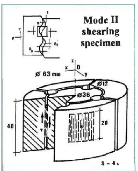
Shear strength is often used to cover several different concepts (Everling 5 1964) such as (i) strength against pure shear, (ii) shear stress required for failure without normal stress, (iii) shear diagram on solid interface depending upon normal stress and (iv) Mohr's stress envelope. Several methods have been devised for measuring the shear strength of rock: torsion test, single shear test, double shear test, punch test, shear loaded beam with starter notches according to mode II of fracture mechanics. The main requirements of a mode II test specimen must be: simple compact geometry, ease of preparation, simple loading system and stress conditions little affected by extremely small geometric alterations. Attempts to realize mode II crack propagation on a laboratory scale usually fail because mode I growths become predominant. On the other hand, traces of mode II growth are often detected at or
z � >20
�
- -
--•i'./
fil20 .. 22J
>80 X�!I"' !'I r--..
t"
1'-y',I/
'\40 1&42-�&63mm >20
Figure I: Direct tension (mode I) test specimen
(Young's modulus Er = 80 GPa, Poisson's ratio v = 0.27 and Tensile strength cr1 = 6.6 MPa).
d
Damage zone
/
L':!.L= c L•w
Figure 2: The basis of the fictitious crack model (Fracture energy GF = 10 J.m·2, Characteristic length t. = 20 mm).
after earthquake slipping. The present paper uses a direct shear test (Luong 19 1990a) that maximizes mode II conditions of crack propagation.
The axial load F is applied on the central cylinder of the specimen, which is retained by the four concentric tubular parts (Figure 3). The notches define the sheared zone S = 4s. The specimen geometry has been optimized by a numerical
analysis of stress intensity factors in mixed modes problems by path independent integrals
Jr
andJrr
(Bui 3 1982). A criterion for deciding whether the crack will grow in mode I by formation and extension of a kink or in mode II in the original crack direction, was established similarly as done by Melin 26 (1986), by comparing the stress intensity factors KJmax for a small kink with KrJmax for the main crack. If Krc and Knc denote the critical stress intensity factors for mode I and II respectively, mode II growth will be preferred to mode I ifX= Kumax I Krmax > Knc I Krc = Xc (1)
It is commonly considered that the strength of rock will become constant if sufficient relative movement is developed (Barton 2 1976). Some authors have suggested that the displacement necessary to develop the residual state increases with rock strength (Krsmanovic et al.14 1966). Various rocks behave differently with regard to relations of the peak and the residual strengths.
The main parameter is the stiffness of the normal loading, able to partially prevent the aggregate interlock breakdown, which softens the mechanical response of the materials. When the tangential displacement or shear slip Ot occurs along the crack interface, the shear stress 't working parallel to the crack is induced and is accompanied by the compressive stress cr and the normal displacement 8n or crack width normal to the crack plane. These four parameters define the deformation characteristics of the cracked interface (Yoshikawa et al.32 1989).
4 Toughness index
A simple method of evaluating the post-cracking performance of rock materials is based on a toughness index that ideally should be a material characteristic, independent of test specimen geometry, dimensions and loading conditions. For ease of comparison and quality control, it should be readily obtained from a load deflection curve of simple tests. Some toughness indices reported in literature (Barr
'I
'
i
Modell.-+
-t 1 shearing 6; specimen . a. •11o
!li63u�Y
s = ••Figure 3 : Direct shear (mode II) test specimen.
ACI
JOHNSlON
BARR 01 •I
s •• s, 4S,
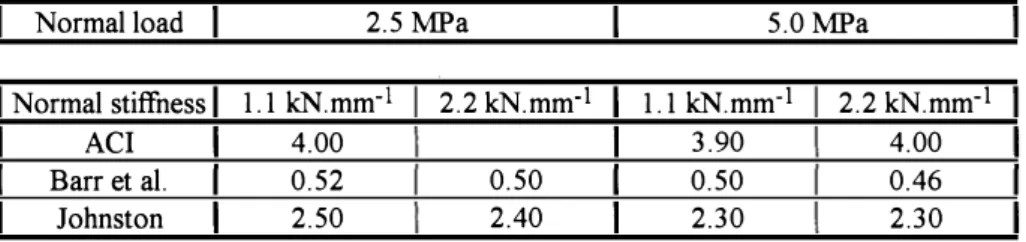
et al.1 1982, Wang and Backer 30 1989) are defined in Figure 4. The toughness index is a measure of the energy absorbed during fracture in the non-linear portion of the load-deflection curve. It gives the numerical value to the toughness and is independent of the units used. The index is particularly useful in analyzing the rheological behavior of rock materials. Using the so-defined toughness indices based on the load-deflection curves, dilatancy effects can be evaluated for mode II and mode III conditions as a function of the normal stiffness (Luong 22 199Ib).
Several series of tests under direct shear loading were performed on specimens of quasi-brittle materials subject to diverse values of normal stress and different types of loading on the sheared interface, in order to analyze the dilatancy effects. The nominal mode II shear strength is given by Ru = F I 4s = 't in relation with the normal
stress cr = Fn I s where Fn denotes the lateral force directly applied on the failure
surface using a variable number of coned discs or Belleville springs for the control of normal loading stiffness.
Table I: Toughness indices of granite subjected to direct shear loading.
Normal load 2.5 MPa 5.0MPa
Normal stiffness 1.1 kN.mm-1 2.2 kN.mm-1 1.1 kN.mm·1 2.2 kN.mm-1
ACI 4.00 3.90 4.00
Barr et al. 0.52 0.50 0.50 0.46
Johnston 2.50 2.40 2.30 2.30
These experimental values show that toughness indices of granite, subjected to direct shear loading, decrease slowly when normal load and normal stiffness increase, demonstrating that dilatancy effects decrease with the occurrence of plasticity, generated by increased mean stresses.
5 Direct torsion strength
When studying the torsion responses of members, it is convenient to identify two different modes of torsion resistance: (i) circulatory torsion and (ii) warping torsion (Krpan and Collins 13 1981). In the former case, the torsion shear stress remains
constant in magnitude from point to point around the cross section and there is no change in magnitude of the longitudinal stresses. In the latter case, torsion shear stresses are not uniform and account must be taken of the variable effects of dilatancy in regard to the difference of normal stiffuess.
Conventional techniques of determining shear strength of rock materials used indifferently tests that promote predominantly mode II or . mode III of fracture mechanics (Lama and Vutukuri 15 1978). In this study, a tubular cylindrical specimen for direct anti-plane shear or torsion testing (Figure
5)
is proposed for the determination of mode III fracture strength of quasi-brittle materials (Luong 21 1991a). It is a square cross section prism with a thin cut turned in its central part. It is assumed that, in spite of the low tensile strength of granite, fracture will occur from shearing stresses in mode III, since the screw-shaped surface of tensile fracture would be much larger than the thin round neck under torsion (Luong 23 1992).(2) The fracture surfaces appear complex, consisting of inclined facets, known as factory roof fracture surfaces by metallurgical workers, formed by the intersection of a large number of independently initiated mode I cracks. Thanks to the thin round neck, mode III or torsion fracture has been preferred as shown by the fracture surfaces, mode I fracture being controlled by the stiffness of normal stress loading or dilatancy effect. The normal stress cr = Fn I 1tr (1 - m2) is applied on the specimen by means of a long screw. The stiffness of normal stress loading on the failure surface is controlled by one or several Belleville springs. The dilatancy effect is evidenced by an increase of nominal torsion strength with the normal loading stifthess.
6 Fracture energy
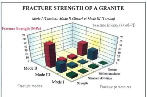
The majority of rock drilling and boring techniques employ principles of mechanical attack by means of which stresses are induced in the rock by impact, abrasion, wedge penetration or cutting, erosion, and sometimes by a combination of these methods. Thus there is a need to evaluate energy spent for fragmentation of rock (Luong and Hoteit 25 1997). Under torsion loading, Figure 6 presents the relationship between fracture energy and strength. The performed tests in this work readily provide energy characteristics to bring the rock materials to fracture in different modes (Figure 7).
Figure 5: Direct torsion (mode III) test specimen.
Fracture energy of a granite under torsion
,.-_ � 50 �
6
= 40 C> ... � C> -30 ... � 'Q = = -= 'Sil = 20 t -{I) 10 0 --·- - -•-J.
• • •JA----'
• 0 w � � � ·l Fracture energy (kJ.m )Figure 6: Fracture energy of granite subject to torsion loading.
FRACTURE STRENGTH OF A GRANITE
70 60
so
Mode 1 (/'ens ion), Mode 11 (Shear) el Mode Ill (l'orsion)
Fracture Energy (kJ.m[-2]}
70 60 so
Fracture modes Fracture parameters
Figure 7: Mechanical characteristics of the tested granite.
Figure 8: Testing arrangement for microcracking detection in granite.
7 Detection of microcracking in granite
In most rocks, both the acoustic velocity and the attenuation vary greatly. According to Koltonski and Malecki 12 (1958), granite, for instance, depending on its grain
·1
structure can reach values from 1.7 to 5.0 km.s . The nondestructive testing (NDT), most extensively used at present, is probably the ultrasonic technique. Several researchers (Jones 11 1952 for instance) used sonic and ultrasonic method to study the fracture of concrete and reported that cracking noises occurred at about 25 % to 75 % of ultimate load. It was recognized that these significant changes in the property of concrete and rocks are probably caused by microcracking, resulting in the increase of volume under compression and the increase of Poisson ratio.
An input-output non parametric procedure (Liu and Vinh 17 1991, Thomas 28 1995), based on ultrasonic pulse propagation and using a non-linear analyser for data reduction, has been chosen to portray the non-linear behavior of rock (Luong 24 1995). The pulse transmission method, using video scan piezoelectric transducer VI 50 (250 kHz), has been applied in conjunction with a pulser-receiver Panametrics 5052PR that provides high-energy broad band performance. The pulser section produces an electrical pulse to excite a piezoelectric transducer, which emits an ultrasonic pulse. The pulse travels through the specimen that is subjected to a given static shearing, to a second transducer acting as a receiver. The transducer converts the pulse into an electric signal that is then amplified and conditioned by the receiver section and made available for non-linear analysis.
The arrangement, used for the detection of microcracking in granite subjected to direct shear loading, is described in Figure 8. Signal records indicate that at 42 % of mode II shear strength, the high order kernels are still negligible. They become very significant at 70 %. They evidenced:
(I)
the occurrence of microcracking that modifies the longitudinal part (the faster) of the pulse signal, and (2) the effects of micro cracking that affect its transversal part (the slower).A simple quantitative parameter on which a criterion could be applied is necessary to characterize the material response. Data reduction based on Volterra series required identification of Volterra kernels through a multi-amplitude procedure, giving access to energy of different terms of the series. Comparison of these energies provides a quantitative evaluation of the significance of non-linear phenomena (Luong 24 1995). The non-linear ratio p(a) is defined as follows:
( ) non-linear energy
p
a
=It expresses the energetic part of non-linear components in the response of the material when subject to an impulse excitation of intensity a. In order to compare two different measurements, it is interesting to use an other parameter called non linear contrast (Thomas 28 1995).
where
8�(a)
=P8(a)- PA (a)
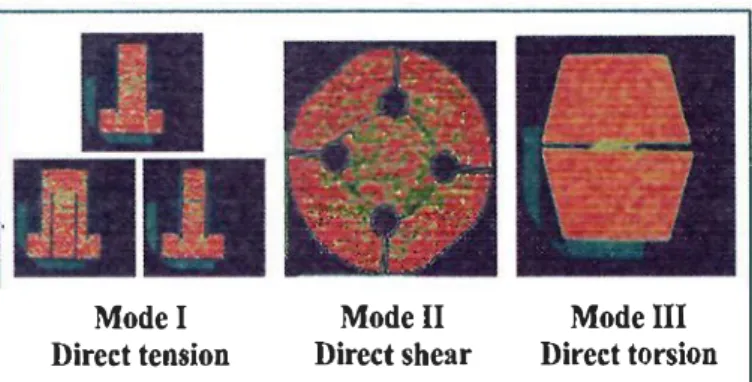
(4)8 X-ray tomodensitometry of granite
Originally used for medical analysis (Hounsfield 9 I 973), the X-ray computerized tomography (CT) technique has been recently used for engineering materials (Vinegar 29 I 986, Latiere and Mazerolle 16 I 987, Withjack 31 I 987, Colleta et al. 4 I 99I). As for conventional radiography, the basic principle of the CT technique is the attenuation of X radiations through materials. This attenuation is mainly dependent on material density, effective atomic number, and thickness. In computerized tomography, a planar fan of rays penetrates the object, and I 024 detectors measure attenuation. Source and detector are attached to a rotor and move on a circular track around the object.
Attenuation is determined at a rate of I 50 measurements per second on each of the I 024 detectors during a 360° rotation, which lasts for 3.4, 6.8 or 13.6 s. During the rotation the X-ray fan investigates a slice of the object that may be 1.5 mm, 3 mm or 8 mm thick. The large number of measurements (about 106 for a 6.8 s time of acquisition) enables attenuation values to be computed for a 5I2 x 5I2 matrix of elements of volume (voxels) in the investigated slice. The computed values produce a 5I2 x 5I2 pixel image, which represents a cross section of the object.
The scanned specimen is translated horizontally through the investigation plane by a motor-driven bed with an accuracy of I mm. Thus it is possible to obtain serial
cross sections of the model. Attenuation values, which are given in Hounsfield units (HU) for 130 kV energy, are compatible with the range of the medical scanner. One of the most significant advantages of computed tomography is its sensitivity to very small differences in density (Figure 9). The internal cracks are visualized. Voids and inclusions can be identified and localized. Figures I 0 and I I demonstrate the great interest of coupling these two non-destructive techniques for the detection of the occurrence of micro cracking in granite.
Model Direct tension Modell Direct shear Mode III Direct torsion Figure 9: Tomography of a granite under fundamental modes of fracture.
Under low shear loading, non-linearities are negligible
Figure 10: Coupled non-destructive techniques used for the detection ofrnicrocracking in granite.
VO&.:I'W.M"-A �K.Nt:t.J.,.S
A..I'.Zf'a..N I'I.'I'QOR.1'1'
Under higher shear loading, non-linearities become predominant
9 Concluding remarks
The versatility of these new testing devices allows a ready evaluation of the behavior of granite during mode I direct tension, mode II direct shear and mode III direct torsion loading.
The proposed testing arrangements for both direct shear and torsion shear strength measurements simplifY the loading equipment by the use of a uniaxial test machine with the combined compression, shear and torsion loading frames described in the paper.
The test set-up allows the normal stresses to be monitored and measured during the experiments under varying shear stresses. The resulting responses are shear stress versus slip and shear stress versus normal stress, which are of course very useful in the interpretation of conventional pull-out tests. They are practical and reliable. They also facilitate the testing procedure when the materials are subject to severe and hostile environmental conditions. They can be used as routine tests more readily achieved than on the conventional triaxial tests in the cases of low mean stress level. In addition they demonstrate the significance of fracture modes on the mechanical behavior of granite.
This ultrasonic technique, using ultrasound propagation characteristics in non linear cracked medium, provides a ready mean to analyze the non-linear response of granite. This method relies on the fact that during the process of micro cracking, rock material is locally unstable and hence obstructs the propagation of ultrasound pulse. The non-linear analyser reveals to be very useful for the detection of the micro cracking process announcing the occurrence of propagating damage. It can be used to monitor nondestructively and continuously the whole fatigue damage process of rock infrastructure so that the damage mechanisms can be quantitatively interpreted.
X-ray computerized tomodensitometry is also of great interest for studying cracking occurrence of rock specimens in mechanical tests. Serial cross-section,s provide useful data for morphological analysis and three-dimensional descriptions of fractures.
Acknowledgments
The support of ANDRA (French Agency for Radioactive Waste Management) is gratefully appreciated.
References
1. B.I.G. Barr et a!., Int. J. Cem. Comp. Light. Concr., 4(4), 221 (1982). 2. N. Barton,Int. J. RockMech. MiningSc., 13,255 (1976).
3. H.D. Bui, C.R. Acad. Sci. Paris, 235, 521 (1982). 4. B. Colletta eta!., Geology, 19, 1063 (1991).
5. G. Everling, Int. J. RockMech. Mining Sc., 1, 145 (1964). 6. W.L. Fourney, Comprehensive Rock Engineering, 4(2), 39 (1983). 7. I. Hawkes and M. Mellor, Engineering Geology, 4(3), 177 (1970). 8. A Hillerborg, Fract. Mech.: Appl. Concrete, ACI SP-118, 157 (1989). 9. G.N. Hounsfield, British J. Radiology, 46, 1016 (1973).
10. Y.S. Jenq and S.P. Shah, Report to RILEM, Committee 89-FMT, (1989). 11. R. Jones, British J. Applied Physics, V, 3(7), 229 ( 1952).
12. W. Koltonski and I. Malecki, Acoustica, 8, 307 (1958).
13. P. Krpan and M.P. Collins, J. Struct. Div., 107(6), 1107 (1981).
14. D. Krsmanovic eta!., Proc. 1st Cong. Int. Soc. RockMech., 1, 537 (1966). 15. R.D. Lama and V.S. Vutukuri, Handbook on mechanical properties of rock,
Trans Tech Pub., 1, (1978).
16. H.J. Latiere and F. Mazerolle, Engineering Fract. Mech., 27(4), 413 (1987). 17. H. Liu and T. Vinh, Mechanical Systems Signals Processing, 5(1), 61 (1991). 18. M.P. Luong, Fracture Concrete & Rock, Elsevier Appl. Sc., 18 (1989). 19. M.P. Luong, Micromechanics of failure of quasi-brittle materials, Elsevier
Appl. Sc., 275 (1990a).
20. M.P. Luong, Engineering Fracture Mechanics, 35(1/2/3), 127 (1990b). 21. M.P. Luong, Fracture Processes in Concrete, Rock and Ceramics, E & FN
SPON, 727 (1991a).
22. M.P. Luong, Mech. Behaviour Materials, Pergamon Press, 4, 141 (1991b). 23. M.P. Luong, J. Nuclear Engineering and Design, 133, 83 (1992).
24. M.P. Luong, Rock Foundation, Balkema , 157 (1995).
25. M.P. Luong and N. Hoteit, Environmental and Safety Concerns in
Underground Construction, Balkema , 525 (1997).
26. S. Melin, Int. J. Fracture, 30, 103 (1986).
27.A Roberts, Geotechnology, Pergamon Press, 103 (1977). 28. J.J. Thomas, Doctorate Ecole Polytechnique, (1995). 29. H.J. Vinegar, J. Petroleum Technology, 257 (1986).
30. Y. Wang and S. Backer, Int. J. Cem. Comp. Light. Concr., 11(1), 11 (1989). 31. E.M. Withjack, Society Petroleum Engineers, SPE 16951, 183 (1987). 32. H. Yoshikawa eta!., J. Struct. Div., ASCE 115(4), 771 (1989).