HAL Id: hal-01349730
https://hal-mines-nantes.archives-ouvertes.fr/hal-01349730
Submitted on 28 Jul 2016
HAL is a multi-disciplinary open access
archive for the deposit and dissemination of
sci-entific research documents, whether they are
pub-lished or not. The documents may come from
teaching and research institutions in France or
L’archive ouverte pluridisciplinaire HAL, est
destinée au dépôt et à la diffusion de documents
scientifiques de niveau recherche, publiés ou non,
émanant des établissements d’enseignement et de
recherche français ou étrangers, des laboratoires
Angle Effect Analysis using PIV Technique and POD for
Post-Processing
Emma Berrich Betouche, Fethi Aloui, Jack Legrand
To cite this version:
Emma Berrich Betouche, Fethi Aloui, Jack Legrand. Turbulent Flows Structures Crossing Conical
Diffusers: Angle Effect Analysis using PIV Technique and POD for Post-Processing. Journal of
Applied Fluid Mechanics, Elsevier, 2016, 9 (Special issue 1), pp.155-164. �hal-01349730�
Journal of Applied Fluid Mechanics, Vol. 9, Special Issue 1, pp. 155-164, 2016. Selected papers from the 7th
International Exergy, Energy
and Environment Symposium, IEEE7-2015
Available online at www.jafmonline.net, ISSN 1735-3645, EISSN 1735-3645.
Turbulent Flows Structures Crossing Conical Diffusers:
Angle Effect Analysis using PIV Technique and POD for
Post-Processing
E. Berrich Betouche
1, F. Aloui
2†, J. Legrand
31 LUNAM Université, Université de Nantes, CNRS, GEPEA, UMR6144, École des Mines de Nantes,4 rue
Alfred KASTLER - BP20722 44307 Nantes Cedex 03 - France -
2. Université de Valenciennes et du Hainaut-Cambrésis (UVHC), LAMIH UMR CNRS 8201, Département de
Mécanique, Campus Mont Houy F-59313 Valenciennes Cedex 9 - France
3. LUNAM Université, Université de Nantes, CNRS, GEPEA, UMR6144, CRTT, -37 Boulevard de l'Université
BP 406, 44602 Saint-Nazaire Cedex-France
†Corresponding Author Email: [email protected]
(Received October 20, 2015; accepted December 10, 2015)
A
BSTRACTIn this work, we investigated experimentally the hydrodynamics of flows crossing conical diffusers. On our previous work (Aloui et al. 2011) CFD turbulent models were validated for flows crossing the critical angle (2=16°). Indeed, the PIV data base constructed was exploited to validate a variant of SST-RLC model. Taking into account the conical diffuser angle effect, the apparition and the development of vortices were observed and studied. The dynamics of the recirculation zones which may be observed at the lower and higher parts of the singularity, has not formed the subject of numerous studies. There were no studies that characterize the vortices at the conical diffusers in terms of size, centre positions, and vortex intensity. Consequently, two conical diffusers were studied using the Particle Image Velocimetry technique (PIV). The results illustrate effects of “opening angle” (2=16°) and (2=30°) on the flow structures developed in such type of diffusers. From such opening angle of conical diffusers, the progressive angle increasing generates a detachment of the boundary layer of the conical diffuser depending on the turbulence level. This detachment may lead to a coherent flow structures. We applied the coherent structures criterion 2 to the recorded
velocity fields to detect and characterize the vortices at the conical diffusers. We used the Proper Orthogonal Decomposition (POD) to filter the PIV data base constructed and to extract the most energetic modes. The results illustrate that the turbulent flow structures can be constituted using a limited number of energetic modes.
Keywords: Conical diffusers; Opening diffuser angle; Flow dynamics; Turbulence; Coherent structures; PIV
technique; 2 criterion; Proper Orthogonal Decomposition POD.
NOMENCLATURE
ai,j temporal coefficient relating to a mode S the surface which surrounds the point P,
D measurement field (m2) t time,
Dh upstream hydraulic diameter (m) u axial velocity component (m/s),
p
d polyamide diameter v radial velocity component (m/s) K Temporal correlation matrix of the Velocity field ub mean inlet velocity (m/s)
L length (m) X, Y, Z coordinates (m)
Q second invariant (m/s) n normal vector in the measurement plan M point of the wide S λ proper value of the matrix,
p pressure 2 kinematic criterion,
PIV velocimetry by Image of Particles vorticity criterion (s-1),
POD Proper Orthogonal Decomposition ρ density
Rc curvature radius of elbow (m) Ω vorticity vector The surface which surrounds the point P,
Re Reynolds number
1. INTRODUCTION
Whether in the fields of energy, chemical engineering, food processing, or more generally in the capital foods industry, the extreme increase of industrial facilities production constraints such as cost, reliability, safety, performance, durability, requires a precise understanding of flows structures through a network of processing elements. Conical diffusers, frequently re-encountered on factories, can modify the flow structures and can generate vortices which, if sufficiently developed, may affect the performance of the production or cleaning in place processing or may even lead to the early exhaustion of the process circuits. The appearance and the amplification of vortex structures involve significant kinetic energy or significant oscillations in the flow or highly asymmetrical recirculation zones.
We focus on turbulent flows structures in conical diffusers by studying experimentally the behaviour of turbulent flow crossing two conical diffusers with opening angle respectively equals to 2α = 16 ° and 30°. This provides a profile of established flow (L/Dh>> 70).
Few studies have been interested to diffusers, either by numerical or experimental approaches. Regarding the first approach, the diffuser was generally considered as isolated element. The problem was reduced to a symmetric or axisymmetric form (Armfield and Fletcher, 1989). Edimilson et al. (2004) studied numerically turbulent flow in small-angle diffusers and contractions using a new wall treatment and a linear high Reynolds κ-ε model. The turbulent flow field was confined in a circular duct with varying cross section. Both expansions and contraction sections were investigated. Equations of boundary-layer type were used and the linear κ-ε model, in its high Reynolds form, was applied. This can limit the representatively of the predicted three-dimensional structures. In experimental studies, the authors do not consider that either moderate angles <16 ° (Cockrell and Bradley, 1971; Spencer et al. 1995) or are restricted to high values of Reynolds number (Re> 1.5 105 (Okwuobi et al. 1989)), or still
consider the output of the diffuser as free (Okwuobi
et al., 1989; McDonald and Fox, 1971). However,
for lower values, the flow through a conical diffuser with opening angle 16 ° may reveal a tendency to cause an intense stable vortices but limited compared to the periphery of the diffuser, a relatively small angular sector (Okwuobi et al. 1989). This phenomenon rarely discussed for conical diffusers, may be closer to the asymmetry observed for planar diffusers (Kline, 1959; Johnston, 1998). However, the specific geometry of
the latter makes it difficult to transpose the analysis of their behaviour to that of conical diffusers. To study the hydrodynamic behaviour of the diffuser, especially the variation of the velocity profile, the researchers has focused mostly on the effect of "swirl" considering that the diffuser exit is free (McDonald and Fox, 1971; Clausen, 1993). Meyer and Nielsen (2004) have more recently looked at the effect of a deviation of the incident flux on the flow at the outlet of the diffuser, generated by a deflection angle of 30 ° elbow placed at the inlet diffuser, but have limited their analysis to output plane (Meyer, Nielsen; 2004).
Most of theoretical studies are interested to planar diffusers. The few studies found for conical diffusers include studies for moderate angles less than 16° or more than 16° (Cockrell et Bradley, 1971; Spencer et al., 1995; Johnston, 1998) with large Reynolds numbers (more than 15 104) or
consider the diffuser exit as being free (Okwuobi et Azad, 1973; Mc Donald and Fox, 1971). All these works consider that the turbulent flow is fully developed in the inlet of the diffuser. For non developed turbulent flows in the upstream of confined axi-symmetric diffusers, no experimental study was found for the critical angle (2=16°). In addition, more interest has been conserved to this particular singularity. On our previous primary work (Aloui et al. 2011), we have qualified the setup and validate CFD turbulence model.
A series of data base including PIV measurements, POD post- processing and structures detection criterions has been constituted for the conical diffusers of “opening angle” (2=16°) and (2=30°); specially designed for this work. The paper proposes an answer to the questions “How does the opening angle affect the hydrodynamic structures of flows crossing conical diffusers?”; “What are the size, the centre positions, and vortex intensity which characterize the vortices at the conical diffusers?”
2. EXPERIMENTAL
INSTALLATION
Nowadays, computer control and data analysis software package are available. In this work, a specially designed setup was constructed for the study of the angle effects of conical diffusers on flows crossing it. We have used the “DANTEC” software “Flow Manager” for the PIV measurements.
2.1 Experimental facility and measurement
techniques
E. Berrich Betouche et al. / JAFM, Vol. 9, Special Issue 1, pp. 155-164, 2016.
157
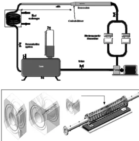
1a. It includes a hydraulic test-section, a tank, a heat exchanger, two parallel electromagnetic flow meters, a pump, and a frequency variator. The hydraulic test-section is made of transparent Plexiglas. The choice of this material is justified by the laser technique used, the Particles Image Velocimetry PIV technique. The diffusers have respectively an angle 2α=16° with a length of
L=75mm and an angle 2α=30° with a length of L=41mm. The upstream diameter of the test section
is Dh = 41mm. We determined how the opening
angle affects the structures of flows crossing these conical diffusers. A specific conception is adopted. It allowed realizing PIV measurements in different geometrical configurations. The idea behind this is to assure that the experimental device can easily be adapted to the different angles, by replacing the conical diffusers. Fig. 1b shows the specific device that ensures a perfect alignment of the different geometries (Fig. 1b). The whole section is integrated in a closed-circuit with a large capacity tank (4m3), in order to guarantee an efficient
degasification of the turbulent flow from small bubbles. The used fluid is water, and its temperature is maintained constant at 20
0.5°C thanks to aheat exchanger. The flow rate is measured by using two parallel electromagnetic flow meters with an accuracy of 0.5% for the measured ranges. The pump, which has a power of 2.5 kW, is placed around its optimal operation output points using a frequency variator. A sufficient straight length has been placed upstream of the test section (L/ Dh >
100), where Dh is the hydraulic diameter of the
conduct in the upstream of the singularity, ensuring a fully developed turbulence upstream of the diffuser (Dh=2*R1).
Fig. 1. Hydraulic channel: (a) Schematic view of the installation, (b) Test section and conical
diffusers (2α=16° and 2α=30°).
The “Velocimetry by Image of Particles” (PIV) is a non-instructive technique used to provide instantaneous velocity field. This technique was used for measurements in a longitudinal cross-section of the conical diffuser in order to determine the instantaneous velocity field in three particular
localizations. The first one is located on the upstream of the conical diffuser. The second one is the total section of the conical diffuser and the third one is located downstream of the progressive enlargement.
In practice, the velocity of micron-sized particles following the flow is measured. In our case, particles of polyamides, with diameters dp20 are m
used.
To apply the PIV technique, the cross-section of flow has to be lighted with a luminous plane via a laser. The recording of the displacement by diffusers of light necessitate a special camera. For the purpose, the PIV system used was composed of a pulsed Nd-Yag 15 mJ laser (New wave Solo), a CCD camera of 1600-1186 pixels resolution (Dantec Dynamics Flow Sense M2/E 8 bit) with an objective Nikon (60 mm) and a “DANTEC” correlator. The whole system is driven by the “DANTEC” software “Flow Manager”.
The flow field’s area studied is the central section of the conical diffuser. For this position, the horizontal laser plane was reflected vertically at z = 0 using a 45° mirror. The CCD camera was placed in front of the lighted diffuser section. For the treatment of measurements, two interrogation areas were been tested: 32 x 32 pixels and 16 x 16 pixels. A comparative study of the treatment results obtained allows choosing 32 x 32 pixels interrogation areas for the study. The PIV measurements are done in three principals positions: in the singularity, upstream and downstream of it. The choice of the measurements plan to position the laser plane and CCD camera is delicate. Indeed, this depends on the localization of the turbulent structures. For certain cases and reasons of checking the appearance of the recirculation zones, series of measurements are added for moderated Reynolds numbers in two other zones of the test section.
2.2 Coherent structures and POD
technique
Chassaing (2000) made a synthesis of several definitions of coherent structure concept: “Anthony Perry, taking a suggestion of John Lumley, defines coherent structure as being recurring reasons for the flow. That does not imply the concept of order, the scales velocity can be unsystematic, but the reasons must have fixed characteristics of orientation to which they become identifiable. It is, according to Kline, of the recurring events which are essential with dynamics such as the production of Reynolds tensions, kinetic dissipation of turbulence energy, and the entities which ensure a momentum transport according to Stull. Wygnanski defines it as being the prevalent mode of instability”. In practice, many criteria are used (Haller, 2005). They play an important role in the study of generation and dissipation mechanisms in fluid mechanic problems. They are usually deduced from the velocity gradient tensor. Among all coherent structures identification techniques, Proper Orthogonal Decomposition (POD) is one of the most objectives, because it does not make
assumptions on the flow (Aloui et al., 2007; Aloui
et al., 2008). The first experimental application was
carried out by Payne and Lumley (1967). Sirovich (1987) introduced the Snapshots method, which is carried out classically from the data characterized by an important space resolution and a few temporal resolutions (measurements PIV unsolved in time). The POD is a promising technique thanks to its various advantages (Rehimi et al., 2011). Indeed, it is optimal in term of energy conservation, and requires only the provision of the flow velocity data. It permits to compress data because a reduced number of modes is enough for well describing and rebuilding the flow structures. These various modes resulting from the decomposition can have a physical direction especially in the presence of coherent structures in the flow.
The analysis of the major structures of turbulent flows crossing the conical diffusers is realized. The determination of the flow coherent turbulent structures was of a big interest.
The vorticity vector is one of the criteria most easily accessible to visualize the turbulent structures of the flow. It permits the measure of the flow rotation rate. Its direction, specifying the rotation axes, is written:
V (1)
where
V
is the velocity vector,
is the rotational operator, and indicates the vector product. Strawn et al. (1999) defined the vortex centre as being a local maximum of the vorticity module. In 2D, the vorticity
is written as follows:1 ( , ) 2 v u x y x y (2)
The swirl centre is identified as a local extremum of the vorticity function.
Taking in consideration the swirl local convection, the
2criterion is defined as follows:
2 . 1 .
M M M S PM U u Z P dS S PM U u (3)where the local velocity of convection is written as: 1
S u UdS S (4)The criterion is a Galilean invariant (Graftieaux 2
et al., 2001).
The objective of criterion is to extract the 2 turbulent structures based on their rotations in the flow, because the vorticity does not make it possible to distinguish between shearing and rotation.
At the moment
t
k, the velocity field ( , , )U x y t is kwritten: ( ) ( ) 1 ( , , ) ( , ) ( ) ( , )
N i i k m k i U x y t U x y a t x y (5)where the coefficient of projection
( )i ( ) k
a t checking the following relation:
( ) ( ) 1 ( ) ( )
N i j k k i ij k a t a t (6)To suitably filter the various velocity fields measured by PIV, the decomposition can be limited to M modes.
According to Sirovich (1987), the POD is a good technique if the number of modes M verifies:
1 1 90%
M i i N i i (7)where N is the number of Snapshots (velocity fields obtained by PIV).
The POD decomposition permits to filter the PIV measurements: ( ) ( ) 1 ( ) ( ) 1 ( , , ) ( , ) ( ) ( , ) ( , , ) ( , ) ( ) ( , )
M i i f m i M i i f m i U x y t U x y a t x y x y t U x y a t x y (8)3.
RESULTS AND DISCUSSION
The main purpose of this paper is to illustrate the conical diffusers opening angles effects on the structures of the turbulent flows crossing it, as it is a topic source of vortex creation. In fact, they may generate the apparition and the development of repetitive and stable vortices. In addition, two configurations are adopted: The first one corresponds to a conical diffuser with an opening angle equal to 2α=16°. The second configuration corresponds to 2α=30°. More interest has been conserved to the conical diffuser (2α=16°) as it presents a critical case i.e no results for this kind of conical diffusers have been found in the literature. In fact, few studies found for conical diffusers include studies for moderate angles less than 16° or more than 16° with large Reynolds numbers (more than 1.5 105) (Cockrell et Bradley, 1971; Spencer et
al., 1995; Johnston, 1998, Jiang et al., 2008; Lee et al., 2012) or consider the diffuser exit as being free
(Okwuobi et Azad, 1973; Mc Donald and Fox, 1971). All these works consider that the turbulent flow is fully developed in the inlet of the diffuser. For non developed turbulent flows in the upstream of confined axi-symmetric diffusers, no experimental study was found for the critical angle (2=16°). In addition, a series of PIV data has been realized. In particular, on the conical diffuser
2α=16° specially designed for this work. It allows
E. Berrich Betouche et al. / JAFM, Vol. 9, Special Issue 1, pp. 155-164, 2016.
159
velocity. We have used the data base constructed to validate CFD simulations. The accuracy of the PIV measurments is about 1% to 2%. The results are obtained from the temporal average (1500 fields).
3.1 Structures of flows crossing conical
diffusers
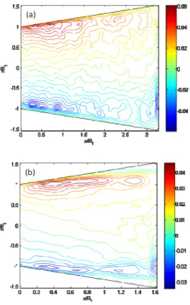
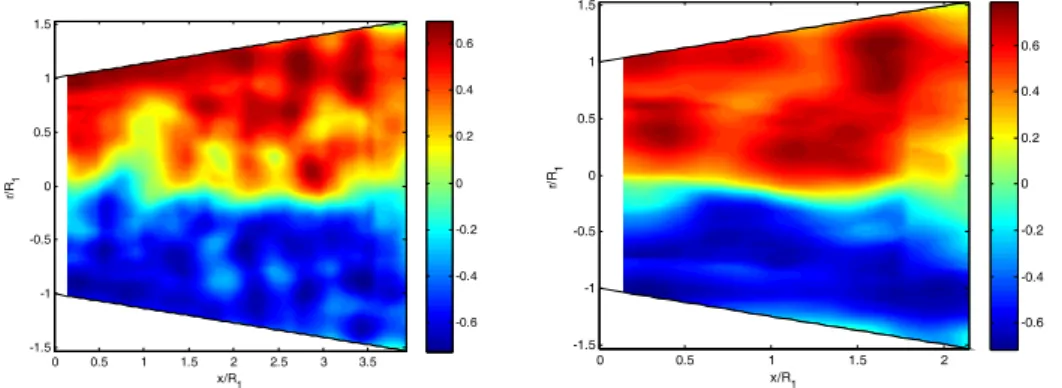
The iso-values lines of the axial component velocity, the iso-values lines of the RMS of the axial component velocity and the iso-values lines of the Reynolds tensor in the conical diffuser (2=16°) for a Reynolds number Re=37000, are presented respectively in Figs. 2. a, 3. a and 4. a. While Figs. 2.b, 3.b and 4.b show the results in the conical diffuser (2=30°).
The Reynolds tensor is defined as:
' '
ij
R u v (9)
The figs show mainly three different regions in the singularity whatever the opening angle considered. The first region was observed in the approximate of nearly aty R/ 1 0.75 from the wall in the direction of mean flow. The second region corresponds to the zone where the pressure gradient is important i.e. at the upper part of singularity. The third region is the lower part near the wall where the pressure gradient is less. This let one deduce that there is a slight dissymmetry of the flow. When the conical diffuser’s section increases progressively; the turbulence level in the singularity increases. Even in the presence of this slight dissymmetry, the turbulence level visualized in the conical diffuser (2=16°) does not generate repetitive and stable vortices. However, when the diffuser opening angle is increased twice i.e. (2=30°), fromr R/ 1 0.4, the iso-values lines
of the axial velocity component have a strong curvature, change directions and generate two circulation zones at the upper and lower part of the diffuser. To conclude, for turbulent flows, when the opening of a symmetrical diffuser exceeds a significant angle, an important separation of the boundary layer of the wall appears. Generally, it induces the formation of a stable recirculation zone characterized by negative values of the axial velocity component close to the wall (Yang and Hou, 1998; Braga and de Lemos, 2004; Mondal et
al., 2004). In a perfectly axi-symmetric diffuser
with a great angle (in our case, 2=30° and a
length of 41mm, a separation alternatively occurs in the top and in the bottom sides. It produces strong vibrations of the flow. This detection is in agreement with the observations of Idel' ick (1969) for diffusers having large point angles, going up to
50 at 60°. The comparison of turbulent flows
behaviours in the diffusers (2α=16°) and (2α=30°) lets deduce that the separation of layers is accompanied by the formation of symmetrical recirculation zones consisted of repetitive and stable contra-rotating swirls when the angle of the diffuser becomes important.
Fig. 2. Iso-values Lines of the axial component velocity for Re=37000: (a) (2=16°); (b)
(2=30°).
Fig. 3. Iso-values Lines of the RMS of the axial component velocity for Re=37000: (a) (2=16°);
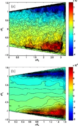
Fig. 4. Iso-values Lines of the Reynolds tensor of the conical diffuser for Re=37000:
(2=16°); (b) (2=30°)
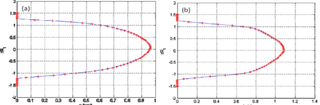
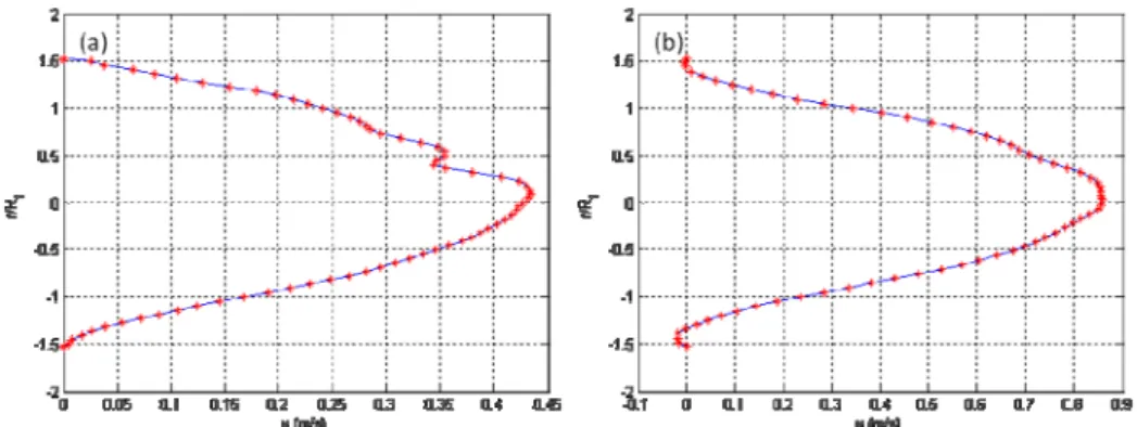
3.2. Velocity profiles of turbulent flows
crossing conical diffusers
The unsteady nature of the flow does not allow an easy interpretation of the charts presented on the preceded section. For more understanding of the opening angle effect on the flow structures variations, we carried out the velocity profiles at different positions along the conical diffusers. This choice was governed by a desire to illustrate the possible apparition of recirculation zones on the diffusers. It allows the localisation of the probable positions of existence of such bifurcations. Indeed, Fig. 5, 6, 7, 8, 9, 10 and 11 demonstrate the velocity axial component profiles along the conical diffusers for Re=37000; respectively at the entry of the diffusers, then at 0.234, 0.42, 0.598, 0.79, 0.88 and 0.97 of the conical diffuser length: (a) (2=16°); (b) (2=30°). These different plots show the evolution of the velocity profiles along the conical diffuser. It illustrates particular shapes with maximum velocity slightly shifted upward relative to the principle flow axis. Indeed, for the conical diffuser with opening angle (2=16°), the slight asymmetry of the profiles, observed compared to the diffuser axis, reveals that the flow dynamics are not amplified by the appearance of a strong dissymmetry, even if it is not the same one in the higher and lower parts of the diffuser. At the wall vicinity, the velocity are lower but still positive both above and below, which proves that there is no recirculation zone in the immediate vicinity of the wall for this type of conical diffuser, under the conditions of the flow tested. However, the asymmetry of these profiles, observed with
respect to the central axis of the singularity, shows that the flow dynamics on the expansion is not the same in the upper and lower parts. However when the opening angle of the conical diffuser increases twice (2=30°), there are negative values of the velocity axial components, in the top and in the bottom of the close zones to the wall. This proves clearly the existence of a recirculation zone (Fig. 9; 10 and 11 (b)). Thus, the negative values of the axial velocity component close to the wall induce the formation of a stable recirculation zone characterized by (Yang Hou, 1998).
Fig. 5. Velocity axial component profile at the beginning of the conical diffuser for Re=37000,
x/Dh = 0: (a) (2=16°); (b) (2=30°).
Fig. 6. Velocity axial component profile at 0.234 of the conical diffuser length for Re=37000:(a)
(2=16°): x/Dh = 0. 4; (b) (2=30°): x/Dh =
E. Berrich Betouche et al. / JAFM, Vol. 9, Special Issue 1, pp. 155-164, 2016.
161
Fig. 7. Velocity axial component profile at 0.42 of the conical diffuser length for Re=37000: (2=16°):
x/Dh = 0. 709; (b) (2=30°): x/Dh = 0.354.
Fig. 8. Velocity axial component profile at 0.598 of the conical diffuser length for Re=37000: (a) (2=16°): x/Dh = 1.0227; (b) (2=30°): x/Dh = 0.5111.
Fig. 9. Velocity axial component profile at 0.79 of the conical diffuser length for Re=37000:(a) (2=16°): x/Dh = 1.338; (b) (2=30°): x/Dh = 0.6687.
Fig. 10. Velocity axial component profile at 0.88 of the conical diffuser length for Re=37000: (a) (2=16°): x/Dh = 1.4963; (b) (2=30°): x/Dh = 0.747.
Fig. 11. Velocity axial component profile at 0.97 of the end of the conical diffuser for Re=37000: (a) (2=16°): x/Dh = 1.634; (b) (2=30°): x/Dh = 0.806.
3.3. Vortex criterion of detection
The vorticity allows the visualization of vortices in a turbulent flow. The instantaneous fields of the vorticity ω in the conical diffusers respectively (2=16°) and (2=30°) obtained after the PIV data processing for Re=37 000 are presented in Fig. 12 (a) and (b). The charts of instantaneous vorticity ω of the flow, through the singularity, show that the behavior of the boundary layer in the critical case i.e. diffuser (2=16°) evolves to a convection mechanism of vortices, without revealing stable and fully developed recirculation zone. The flow visualization in the progressive expansion of low angle (2=16°) revealed a slight disturbance of the global dynamics with a detachment both above and below, from a length of about ¼ of the total length of the cone. This separation is more significant and appears a little early at the bottom than the top of the cone. This is due to the asymmetry already detected in accordance with the Idelc'ick deductions (1969). The vortex structures are not observed and followed by the creation of a stable and well developed recirculation zone. While a stable and fully developed one appears in the conical diffuser (2=30°). The sub-layers separation and the vortices formation phenomena are related to the presence of velocity difference across a given section and a positive pressure gradient along the flow.
The use of the vorticity as a criterion for detecting vortex structures is not suitable in the presence of significant shear wall. In this case, the use of the 2 criterion is generally preferable because they are not sensitive to shear.
The instantaneous field of the 2 criterion obtained
after the post-processing of PIV data on 7 layers for Re=37000 respectively for the conical diffuser (2=16°) and the conical diffuser (2=30°) is illustrated on Fig. 13. The results for the conical diffuser (2=16°) show the presence of high levels of turbulence and detachment of the boundary layer near the wall with a concrete existence of vortex but not necessary repetitive (no recirculation zones) . As it can be seen, there is a detachment without stable turbulent zones. By
Fig. 12. Sampling of detection criterion, instantaneous , in isolated conical diffusers for
Re=37000: (a) (2=16°); (b) (2=30°). comparing the instantaneous field of the 2
criterion obtained for the conical diffuser (2=16°) to this obtained for the conical diffuser (2=30°) under the same conditions, we conclude that no strongly developed dissymmetrical structure appears in the first one while in the second one, a strong level of turbulence is detected and which caused the apparition of a strongly developed dissymmetrical structure in the singularity (2=30°).
3.4. Proper Orthogonal decomposition
The instantaneous vorticity field ω obtained after thepost-processing of the PIV data by POD (11 modes), superimposed with the streamlines, respectively in the conical diffusers 2=16° and 2=30° is presented on Fig. 14. As it can be seen, two results were demonstrated. The first one concerns the effect of the opening angle. In fact, the instantaneous vorticity field obtained respectively in the conical diffuser 2=16°, after
E. Berrich Betouche et al. / JAFM, Vol. 9, Special Issue 1, pp. 155-164, 2016.
163
x/R1 r/ R1 0 0.5 1 1.5 2 2.5 3 3.5 -1.5 -1 -0.5 0 0.5 1 1.5 -0.6 -0.4 -0.2 0 0.2 0.4 0.6 x/R1 r/ R1 0 0.5 1 1.5 2 -1.5 -1 -0.5 0 0.5 1 1.5 -0.6 -0.4 -0.2 0 0.2 0.4 0.6Fig. 13. Instantaneous 2 criterion obtained for the conical diffuser from PIV measurements after
post-processing, and for Re=37000: (a): (2=16°); (b) (2=30°).
the post-processing of the PIV data by POD (11 modes), superimposed with the streamlines, shows that when the opening angle is 2=16°, the recirculation zones are not present. While, the instantaneous vorticity field smoothed by POD, obtained in the conical diffuser (2=30°) illustrate the presence a fully and developed recirculation zone. The second result concerns the analysis of the POD decomposition effect. In addition, the comparison of the PIV field with that obtained following the treatments by POD (filtering with 11 modes) illustrates that smoothing by POD of measurements resulting by PIV permits to stress the important turbulence level. Following this filtering, we noted the existence of a three-dimensional effect of the flow which cannot be highlighted by the single post-processing of the 2D PIV data. However, while being limited to the energy modes, the POD has allowed us then to collect this phenomenon of three-dimensionality.
4. CONCLUSION
The behaviours of flows crossing conical diffusers of opening angles respectively equals to (2=16°) and (2=30°) were studied using PIV and POD techniques and some criterions for the detection of the turbulent flows structures such as the instantaneous vorticity and the 2 criterion.
Many differences were found in comparing results. In the two conical diffusers, the PIV data base illustrate that the flow crossing the singularities was fully developed and turbulent. The iso-values lines of the axial component velocity, the iso-values lines of the RMS of the axial component velocity and the iso-values lines of the Reynolds tensor were presented for the two diffusers. They highlighted the strong variations of the flow depending on the diffuser opening angle. The comparative analysis achieved illustrate that the opening angle strongly affect the turbulence level of flow crossing the conical diffusers and more generally the hydrodynamic structures of the flows. In fact, the analysis of the velocity profiles evolution along the conical diffusers demonstrates a detachment on the near vicinity of the wall. Symmetrical recirculation zones appear in the upper and lower parts of the conical diffuser
X/Dh Y/ Dh 0 0.25 0.5 0.75 1 1.25 1.5 1.75 -0.75 -0.5 -0.25 0 0.25 0.5 0.75 -0.15 -0.1 -0.05 0 0.05 0.1 0.15 X/Dh Y/ Dh 0 0.1 0.2 0.3 0.4 0.5 0.6 0.7 0.8 0.9 -0.75 -0.5 -0.25 0 0.25 0.5 0.75 -0.15 -0.1 -0.05 0 0.05 0.1 0.15
Fig. 14. Instantaneous vorticity field
obtained By POD (11 modes), superimposed with the streamlines, in the conical diffuser for
Re=37000: (a): (2=16°); (b) (2=30°).
(2=30°). It consisted of repetitive and stable contra-rotating swirls. While the opening angle of the diffuser is reduced to approximately 2=16°, for the minimum Reynolds number generally used in agri-food industries for the cleaning in place processes, even the slight dissymmetry detected does not generate a sufficient turbulence level which can be followed by the creation of repetitive and stable vortices.
The instantaneous field of the 2 criterion obtained after the post-processing of PIV data on 7 layers for Re=37000 respectively for the conical diffuser (2=16°) and the conical diffuser
(2=30°) was shown. It illustrates the presence of high levels of turbulence and a detachment of the boundary layer near the wall with a concrete existence of vortex but not necessary repetitive for conical diffuser (2=16°).
The POD technique was used in order to extract the coherent flow structures and to filter the different Snapshots. The POD decomposition allowed the reconstruction of the flow structures with limited energy modes. Indeed, the instantaneous vorticity field obtained directly by PIV and by POD (11 modes), superimposed with the streamlines, in the conical diffusers are presented. It allows the visualization of vortices in a turbulent flow. The POD results detect the presence of 3D effects.
REFERENCES
Aloui, F., E. Berrich, and D. Pierrat (2011). Experimental and Numerical investigation of a turbulent flow behavior in isolated and Nonisolated Conical diffusers, J. Fluids Eng.,
133 (1), 011201-10.
Armfield S. W. and C. A. J. Fletcher (1989) Comparison of k –ε and algebraic Reynolds stress models for swirling diffuser flow, Int. J.
of Num. Meth. In Fluids, 9(8), pp. 987-1009
Chassaing, P. (2000) Turbulence en mécanique des fluides : Analyse du phénomène en vue de sa modélisation à l’usage de l’ingénieur, Édité par CÉPADUÉS., Coll. POLYTECH de l’INP de Toulouse, 255.
Clausen P. D., S. G. Koh, and D.H. Wood (1993) Measurements of a swirling Turbulent Boundary Layer Developing in a Conical Diffuser, Experimental Thermal and Fluid
Science, 6, pp.39-48.
Cockrell, D. J., and C. L. Bradley (1971) The
response of diffusers to flow conditions at their inlet. Symp. On Internal Flows, University of
Stanford, pp. 32-41.
Edimilson J. Braga, and J.S Marcelo. de Lemos, Numerical Simulation of Turbulent Flow in Small-Angle Diffusers and Contractions using a New Wall Treatment and a Linear High Reynolds k-e Model, Num. Heat Transfer, A,
45: pp.911-933.
Graftieaux, M., L. Lollini, and N. Grojean (2001) Combining PIV, POD and Vortex identification algorithms for the study of unsteady turbulent swirling flows,
Measurement Science and Technology, 12, pp.
1422-1429.
Guo, J, and Y. J. Pierre (2003) Modified log-wake law for turbulent flow in smooth pipes, Journal
of Hydraulic Research, 41 (5), pp. 493-501.
Haller, G. (2005) An objective definition of a vortex. Journal of Fluid Mechanics 525, pp. 1– 26.
Hunt, J. C. R., A. A. Wray, and P. Moin (1988) Eddies, Stream and convergence zones in Turbulent flows, Center for Turbulence Research, Report CRT-S88, 193.
Idelc'Ick, I. (1969) Memento des pertes de charges, Edition EYROLLES, Paris.
Jiang, G., Y., S. He Shu, and Y. Xiao (2008) Numerical prediction of inner turbulent flow in conical diffuser by using a new five-point scheme and DLR k-ε turbulence model,
J.Cent.SouthUniv, 15, pp. 181–186.
Johnston, J. P. (1998) Review: Diffuser design and performance analysis by a unified integral method, J. of Fluids Engineering, 120, pp. 6-17.
Kline S. J. (1959) On the nature of stall, Transactions of the ASME, J. of Basic
Engineering, 21, D (3), pp. 305-320.
Lee J., S. Jae Jang, and H. Jin Sung, (2012) Direct numerical simulations of turbulent flow in a conical diffuser, Journal of Turbulence, 13 (30), pp. 1–29.
Mc Donald, R. V., and R. W. Fox, (1971) Effects of Swirling Inlet Flow on Pressure Recovery in Conical Diffusers, AIAA Journal, 0001-1452,
9(10), pp. 2014-2018.
Meyer, K., and L. Nielson (2014) Flow Structures in Large-angle conical diffusers measured by PIV, 12 th int. Symposium on application of laser techniques to fluid mechanics, Lisbon, Portugal, 12-15 July, 2004.
Okwuobi, P. A. C, and R.S. Azad (1973) Turbulence in a conical with fully developed flow at entry, J. Fluid Mech. 57(3), pp. 603-622.
Payne, F., and J. Lumley (1967) Large eddy structure of the turbulent wake behind a circular cylinder, Phys. Fluid. 182, pp. 1-22. Rehimi, F., F. Aloui, and S. Ben Nasrallah (2011)
Reorganization of Coherent Structures Downstream a Circular Cylinder Located between Two Parallel Walls, Journal of
Applied Fluid Mechanics, 4(2), Issue 1, pp.