HAL Id: hal-02115618
https://hal-univ-rennes1.archives-ouvertes.fr/hal-02115618
Submitted on 7 Jul 2020HAL is a multi-disciplinary open access archive for the deposit and dissemination of sci-entific research documents, whether they are pub-lished or not. The documents may come from teaching and research institutions in France or abroad, or from public or private research centers.
L’archive ouverte pluridisciplinaire HAL, est destinée au dépôt et à la diffusion de documents scientifiques de niveau recherche, publiés ou non, émanant des établissements d’enseignement et de recherche français ou étrangers, des laboratoires publics ou privés.
Communication Systems
Hamsakutty Vettikalladi, Waleed Tariq Sethi, Ahmad Fauzi Bin Abas,
Wonsuk Ko, Majeed A. Alkanhal, Mohamed Himdi
To cite this version:
Hamsakutty Vettikalladi, Waleed Tariq Sethi, Ahmad Fauzi Bin Abas, Wonsuk Ko, Majeed A. Alkan-hal, et al.. Sub-THz Antenna for High-Speed Wireless Communication Systems. International Journal of Antennas and Propagation, Hindawi Publishing Corporation, 2019, 2019, pp.9573647. �10.1155/2019/9573647�. �hal-02115618�
Research Article
Sub-THz Antenna for High-Speed Wireless
Communication Systems
Hamsakutty Vettikalladi
,
1Waleed Tariq Sethi,
2Ahmad Fauzi Bin Abas
,
1Wonsuk Ko,
1Majeed A. Alkanhal,
1and Mohamed Himdi
21Department of Electrical Engineering, College of Engineering, King Saud University, 11421 Riyadh, Saudi Arabia
2IETR University of Rennes 1, France
Correspondence should be addressed to Hamsakutty Vettikalladi; hvettikalladi@ksu.edu.sa
Received 9 October 2018; Revised 27 December 2018; Accepted 1 January 2019; Published 27 March 2019 Academic Editor: Ikmo Park
Copyright © 2019 Hamsakutty Vettikalladi et al. This is an open access article distributed under the Creative Commons Attribution License, which permits unrestricted use, distribution, and reproduction in any medium, provided the original work is properly cited.
Terahertz (THz) links will play a major role in high data rate communication over a distance of few meters. In order to achieve this task, antenna designs with high gain and wideband characteristics will spearhead these links. In this contribution, we present
different antenna designs that offer characteristics better suited to THz communication over short distances. Firstly, a
single-element antenna having a dipole and reflector is designed to operate at 300 GHz, which is considered as a sub-terahertz
band. That antenna achieves a wide impedance bandwidth of 38.6% from 294 GHz to 410 GHz with a gain of 5.14 dBi. Secondly, two designs based on the same dipole structure but with added directors are introduced to increase the gain while maintaining almost the same bandwidth. The gains achieved are 8.01 dBi and 9.6 dBi, respectively. Finally, an array of 1 × 4 elements is used
to achieve the highest possible gain of 13.6 dBi with good efficiency about 89% and with limited director elements for a planar
compact structure to state-of-the-art literature. All the results achieved make the proposed designs viable candidates for high-speed and short-distance wireless communication systems.
1. Introduction
Over the last few years, wireless data traffic has been drasti-cally increasing due to a change in the way today’s society creates, shares, and consumes information. This change has been accompanied by an increasing demand for much higher speed wireless communication anywhere at any time. In particular, wireless data rates have doubled every eighteen months over the last three decades and are quickly approaching the capacity of wired communication systems. Following this trend, wireless terabit-per-second (Tbps) links are expected to become a reality within the nextfive to ten years [1]. Advanced physical layer solutions and, more importantly, new spectral bands will be required to support these extremely high data rates [2].
Terahertz (THz) and sub-THz communication refers to the use of the band that coves region from (0.1–10) THz and sub-THz region is covered from (0.1–0.3) THz [1].
THz communication links will play a major role in which very high data rates are required over short distances. Tera-hertz band can be used for high-speed data transmission within a range of 10 m. This coverage area consists of small cells of cellular networks. Terahertz communication is appli-cable in the indoor as well as outdoor environments with sta-tionary and mobile users. Terabit wireless local area networks (T-WLAN) can provide flawless communication between high-speedfiber optical links and personal laptops and tab-lets. Wired and wireless links enjoy the same speed in tera-hertz communication [2]. Very high path loss is imposed as one of the main challenges at THz band frequencies, which poses a major constraint on communication distances. Addi-tional challenges range from the implementation of compact high-power THz band transceivers, the development of efficient ultra-broadband antennas at THz Band frequen-cies, and characterization of the frequency-selective path loss of the THz band channel to the development of novel
Hindawi
International Journal of Antennas and Propagation Volume 2019, Article ID 9573647, 9 pages https://doi.org/10.1155/2019/9573647
modulations, transmission schemes, and communication protocols tailored to the peculiarities of this paradigm. Many of these challenges are common to mm-wave com-munication systems, and as a result, the THz band is not yet regulated [3].
One of the major advantages of THz and sub-THz fre-quencies is the antenna size, which reduces to about sub-millimeter [4]. The implementation of these systems is now possible due to the advancements in the realization of the photonic and semiconductor devices with an operat-ing frequency in the terahertz band. A common approach is to design the antenna in a low loss substrate and then inte-grate it to the active devices. On-chip antennas are easily integrated to the rest of the system but they have lower effi-ciencies due to the lossy substrate [5–7]. The substrate inte-gration technology, one of the technologies used in THz, converts nonplanar antenna structures into their planar forms. Advanced microfabrication techniques are adopted for the design of terahertz antennas. Some of the
substrate-integrated antenna structures used in THz technology are slot array, dipole, reflector, horn, and leaky wave antennas [8]. For the sub-THz designs, high gain with compact size and wide bandwidth is preferred. Some antennas have been presented in literature such as in [9] where authors pre-sented three antenna designs (rectangular horn, Cassegrain,
h1 h2 Reflector h3 Gold Driven dipole Feed InP BCB (a) Ws Wf Wf g d2 d3 Lf Ld Lr d1 Ls Wf (b)
Figure 1: Geometric design of single-element dipole antenna: (a) perspective view and (b) front view. Table 1: Optimized dimensions of single-element dipole antenna.
Dimensions Value (μm) d1 78 d2 116 d3 82 h1 50 h2 6 h3 2 g 4 Lf 35 Lr 280 Ld 115 Wf 10 dBi 5.74 3.94 2.87 1.79 0.717 −2.14 −8.57 −15 −21.4 −27.8 −34.3 Phi x z y Theta x y z x y z dB 5.14 3.54 2.57 1.61 0.643 −2.18 −8.71 −15.2 −21.8 −28.3 −34.9 y Phi x Theta z
Figure 2: Reflection coefficient (S11) and gain (dB) of
5.74 dBi phi x y z Theta 3.94 2.87 1.79 0.717 -2.14 -8.57 -15 -21.4 -27.8 -34.3
(a) 3D directivity of single-element dipole
5.14 dBi 3.54 y x phi Theta z 2.57 1.61 0.643 -2.18 -8.71 -15.2 -21.8 -28.3 -34.9
(b) 3D gain of single-element dipole
60 30 90 120 150 180 210 6 4 2 0 –2 –4 –6 –8 –10 –12 –12 –10–8 –6 –4 –20 2 4 6 240 270 300 330 0 CST_gain HSFF_gain
(c) E-plane versusϕ: Eϕ at θ=90°
60 30 90 120 150 180 210 6 4 2 0 –2 –4 –6 –8 –10 –12 –12 –10–8 –6 –4 –20 2 4 6 240 270 300 330 0 CST_gain HSFF_gain
(d) H-plane versusθ: Eϕ at ϕ=0°
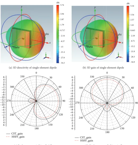
Figure 3: Radiation pattern of the single-element dipole antenna at 300 GHz: (a) 3D directivity, (b) 3D gain, (c) E-plane, and (d) H-plane.
h3 Director Gold Driven dipple Feed Reflector BCB InP h1 h2 (a) Ws Wf Wf Wf Ld d3 d2 d1 d1´ d1´ Ld1 Ls g Lr Lf Wf (b)
Figure 4: Geometric design of single-element dipole antenna with 3 directors: (a) perspective view and (b) front view.
3 International Journal of Antennas and Propagation
and off-set parabolic type) for achieving high gain charac-teristics at 300 GHz. They were able to achieve gains of around 25 dBi for alleviating link noises, but the size was not compact enough. Similarly, authors in [10] presented a rectangular cavity design based on InP substrate having multilayers. They achieved a wide impedance bandwidth of 38 GHz around the center frequency of 300 GHz with limited gain of 4 dBi. In [11], authors used CMOS on-chip technol-ogy to design a broadband sub-THz antenna. Four resona-tors were placed in top of a microstrip patch antenna. The authors were able to achieve a fractional bandwidth of 10% with radiation efficiency of 15% at the center frequency. The complications were in the manufacturing and measuring capability as every step is needed to be as precise as possible. With the above literature review discussion, it can be seen that possibilities of designing sub-THz antenna at 300 GHz are a lot but limitations are presented in terms of trade-off between acquiring wide bandwidths, high gain, and complex structures. In this paper, we propose a simple antenna design solution that presents better results in terms of wide band-width and high gains at the sub-THz band. We propose a single-element design based on dipole technology that offers a much wider bandwidth and acceptable gain. Next, we intro-duce different radiating directors and array design to increase the gain of the structure while maintaining a compact size and wide bandwidth.
2. Antenna Designs and Results
The following sections will discuss the antenna design geom-etry and its simulation results performed in electromagnetic simulator CST Microwave Studio [12] with verifications done on commercially available simulator HFSS [13]. For all the designs, i.e., single element, enhanced gain with 3 directors, enhanced gain with 5 directors, and the array, the substrate materials used were indium phosphide (InP) and benzocyclobutene (BCB).
2.1. Single-Element Dipole with a Reflector. The geometry of the proposed single-element design is depicted in Figure 1. The perspective and front views are presented. The single-element design is based on a dipole antenna resonating at the center frequency of 300 GHz. A reflector element is placed behind the dipole. Both of the elements are made with gold as a conducting material with conductivityσ = 4 561 × 107S/m. The placement of reflector is for the purpose of
increasing the directivity and gain of the single-element antenna. Its distance is approximately λ/4 from the dipole element at the center frequency. All the conducting elements, starting from the bottom layer to top, are placed on InP and BCB substrates. BCB has electrical properties of mittivity (2.5) and loss tangent (0.005) while InP has per-mittivity (12.5) and loss tangent (0.003) [11], respectively. The whole antenna occupies a small footprint of Ls× Ws=
322 × 280 × 58 μm3. The remaining optimized dimensions
of the single-element design are listed in Table 1.
Figure 2 shows the simulated results in terms of reflec-tion coefficient (S11) and gain (dBi) of the proposed
single-element dipole antenna. The results have been verified with another simulator HFSS. The similarity between them confirms the design scenario and its output results. The antenna covers a wide impedance bandwidth of 116 GHz (294-410 GHz) with the gain of 5.14 dBi at the center fre-quency of 300 GHz. Since the antenna is placed parallel to the y-axis, it should radiate in the end-fire direction (x-axis) as per E-field excitation and it is also evident by the place-ment of reflector.
The antenna radiation pattern in terms of directivity and gain is depicted in Figures 3(a)–3(b). The 3D pattern confirms its radiation in the end-fire direction with the directivity and gain of 5.74 dBi and 5.14 dBi, respectively, while the polar plots in both the E-plane and H-plane are depicted as well in Figures 3(c)–3(d). The E-plane (xy or
θ = 90°) presents the antennas side lobe levels at -12.4 dB
and angular beam width of 123.37°. Similarly the H-plane (xz or Ø = 0°) has a side lobe levels of -12.4 dB and angular beam width of 97.9°. Here again, HFSS was used to confirm the simulation results. Good efficiency is obtained and it is about 87%.
Although the proposed single-element dipole antenna produced a wide bandwidth response, but the gain was not enough for sub-THz design. In order to increase the gain of the antenna while maintaining the same wider bandwidth, the next subsections will discuss the effects of adding con-ducting radiators or directors to the design especially in front of the main driven element.
Table 2: Optimized dimensions of single-element dipole antenna with 3 directors. Dimensions Value (μm) d1 135 d2 164 d3 116 d1 125 Ld1 150 Ls 822 Ref lec tio n co ef ficien t (S 11 ) –40 –35 –30 –25 –20 –15 –10 –5 0 5 10 –40 –35 –30 –25 –20 –15 –10 –5 0 5 10 M axim um ga in (dB i) 280 300 320 Freq (GHz) 340 360 380 400 420 Gain-HFSS Gain-CST S11-HFSS S11-CST
Figure 5: Reflection coefficient (S11) and gain (dB) of
2.2. Single-Element Dipole with 3 Directors. The geometric design of the single-element dipole with three directors made of the same conducting material, i.e., gold, is depicted in Figure 4. The same substrate materials InP and BCB have been utilized. Most of the dimensions are the same as was for the single-element design. The addition in terms of dimensions is listed in Table 2.
With these optimized dimensions, the antenna provides an impedance bandwidth of 98 GHz (293-391 GHz) with a gain of 8.01 dBi which can be seen in Figure 5. Optimization was done in such a way that almost wide bandwidth is maintained. The introduction of three directors placed at certain distances proved to be worthy in terms of achieving better gain.
This achievement can be seen from the radiation pattern results in the 3D and 2D polar plots depicted in Figures 6(a)– 6(d). At the center frequency of 300 GHz, the antenna radi-ates with the directivity and gain of 8.44 dBi and 8.01 dBi, respectively. In this case, the efficiency is much better to the last dipole and it is about 90%. From the polar plots, the E-plane has a side lobe levels of -10.8 dB and angular beam width of 77.9°. The H-plane on the other hand offers
a side lobe levels of -10.8 dB and angular beam width of 76.7°.
2.3. Single-Element Dipole with 5 Directors. In order to further increase the gain of the antenna while keeping the size compact and bandwidth wider, two more directors were added to the previous design thus forming the 5-director single-element dipole antenna. Its geometric design with optimized dimensions is presented in Figure 7 and Table 3, respectively.
The antenna was able to maintain a wide bandwidth around 82 GHz (294-376 GHz) and gain of 10.2 dBi which can be seen in Figure 8.
With 5 directors in place, the antenna further enhanced the performance with better gain results. Figures 9(a)–9(d) show the radiation pattern of the antenna in 3D and 2D plots at the center frequency of 300 GHz. The antenna radiates with the directivity and gain of 10.2 dBi and 9.61 dBi, respec-tively. Due to a number of metallic element, the efficiency is reduced compared to the 3 directors but it remains good and it is about 87.3%. Theta Phi x z dBi 8.44 5.8 4.22 2.64 1.05 −1.97 −7.89 −13.8 −19.7 −25.6 −31.6
(a) 3D directivity of single-element dipole antenna with 3 directors
dB 8.01 5.51 4.01 2.5 1 −2 −8 −14 −20 −26 −32 Phi x Theta z
(b) 3D gain of single-element dipole antenna with 3 directors
10 5 0 −5 −10 −15 −15 −10 −5 0 5 10 60 30 90 120 150 210 240 270 300 330 0 180 CST_gain HSFF_gain
(c) E-plane versusϕ: Eϕ at θ=90°
CST_gain HSFF_gain 60 30 90 120 150 210 240 270 300 330 0 180 10 5 0 −5 −10 −15 −15 −10 −5 0 5 10
(d) H-plane versusθ: Eϕ at ϕ=0°
Figure 6: Radiation pattern of the single-element dipole antenna with 3 directors at 300 GHz: (a) 3D directivity, (b) 3D gain, (c) E-plane, and (d) H-plane.
5 International Journal of Antennas and Propagation
From the polar plots, the E-plane has a side lobe levels of -13.3 dB and angular beam width of 63°. The H-plane on the other hand offers a side lobe levels of -13.9 dB and angular beam width of 62.7°.
3. Array Design and Results
Final design improvement was done to the single element with 5 directors in terms of presenting a linear array struc-ture. Figure 10 presents the geometric dimensions of the 1 × 4 linear array with individual excitation. The geometric dimensions were the same as the single-element dipole with 5 directors provided earlier in Table 3. The distance between the array elements (m = 220 μm) was less than λ/2 which gave good isolation among the radiators.
The array provided with a wide impedance bandwidth of 82 GHz (294-376 GHz), better mutual coupling of -20 dB and increased gain of 13.6 dBi. Figure 11 presents the reflection coefficient and mutual coupling coefficient results along with achieved gain at the center frequency of 300 GHz.
Figure 12 shows the gain improvements by depicting the radiation patterns of the 1 × 4 array at the center frequency of 300 GHz. The array achieves directivity and gain of 14.1 dB and 13.6 dB, respectively. The efficiency remains good and it is about 89%. Of course, the final efficiency will depend to feeding array losses. From polar plots, the E-plane has side lobe levels of -10.2 dB and angular beam widths of 55 while the H-plane has side lobe levels of -11.3 dB with angular beam widths of 23.3 .
4. Conclusion
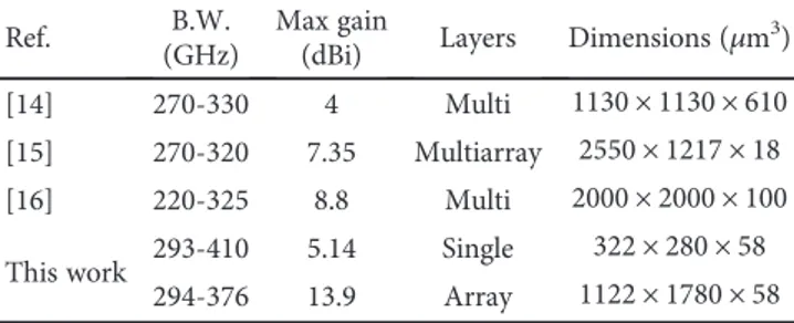
For sub-THz applications working at 300 GHz, we have proposed a single element and an array design based on the dipole technology. The single-element dipole achieved a wide impedance bandwidth of 38% (294-410 GHz) with a gain of 5.14 dBi as compared to other similar works
BCB InP h1 h3 h2 Gold Driven dipole Feed Director Reflector (a) Ws Wf Wf g Wf Ld Lf d3 d1 d2 d1´ d1´ d1´ Ld1 Lr Ls (b)
Figure 7: Geometric design of single-element dipole antenna with 5 directors: (a) perspective view and (b) front view. Table 3: Optimized dimensions of single-element dipole antenna
with 5 directors. Dimensions Value (μm) d2 188 d3 92 Ls 1122 −40 −35 −30 −25 −20 −15 M axim um ga in (dB i) Ref lec tio n co ef ficien t ( S11 ) −10 −5 0 5 10 −40 280 300 320 Freq (GHz) 340 360 380 −35 −30 −25 −20 −15 −10 −5 0 5 10 Gain-HFSS Gain-CST S11-HFSS S11-CST
Figure 8: Reflection coefficient (S11) and gain (dB) of dipole
dB1 Phi Theta x z 10.2 7.01 5.1 3.19 −1.28 −1.86 −29.8 −7.45 −13 −18.6 −24.2
(a) 3D directivity of single-element dipole antenna with 5 directors
dB Phi Theta x z 9.61 6.61 4.8 3 −1.2 −24.7 −30.4 −1.9 −7.6 −13.3 −19
(b) 3D gain of single-element dipole antenna with 5 directors
60 30 90 120 150 180 210 240 270 300 330 0 −5 5 0 10 −10 −15 −15 −10 −5 0 5 10 CST_gain HSFF_gain
(c) E-plane versusϕ: Eϕ at θ=90°
60 30 90 120 150 180 210 240 270 300 330 0 −5 5 0 10 −10 −15 −15 −10 −5 0 5 10 CST_gain HSFF_gain
(d) H-plane versusθ: Eϕ at ϕ=0°
Figure 9: Radiation pattern of the single-element dipole antenna with 5 directors at 300 GHz: (a) 3D directivity, (b) 3D gain, (c) E-plane, and (d) H-plane. d1´ d1´ d1´ m d1´ L s d2 d3 Wf Wf Lr Ws Wf Lf Wf g Ld Ld1
Figure 10: Geometric design of 1 × 4 array having single-element dipole antenna with 5 directors.
7 International Journal of Antennas and Propagation
–40 –35 –30 –25 –20 –15 –10 –5 0 5 10 –40 –35 –30 –25 –20 –15 –10 –5 0 5 10 M axim um ga in (dB i) Ref lec tio n co ef fi cien t ( S11 ) 280 300 320 340 360 380 Gain-HFSS Gain-CST S11-CST S11-HFSS S22-CST S22-HFSS S33-CST S33-HFSS S44-CST S44-HFSS Freq (GHz) (a) S12-CST S12-HFSS S13-CST S13-HFSS Freq (GHz) In se tio n los s (dB) S14-CST S14-HFSS S21-CST S21-HFSS S23-CST S23-HFSS S24-CST S24-HFSS S31-CST S31-HFSS S32-CST S32-HFSS S34-CST S34-HFSS S41-CST S41-HFSS S42-CST S42-HFSS S43-CST S43-HFSS 280 –80 –70 –60 –50 –40 –30 –20 –10 0 300 320 340 360 380 (b)
Figure 11: 1 × 4 array dipole antenna with 5 directors: (a) reflection coefficient (Snn) and gain (b) mutual coupling coefficient (Smn).
phi dBi x 14.1 9.69 7.05 4.41 1.76 −1.62 −6.48 −11.3 −16.2 −21 −25.9 y
(a) 3D directivity of the 1 × 4 array having single-element dipole antenna with 5 directors
dB phi x y 13.6 9.36 6.81 4.26 1.7 −1.65 −6.6 −11.5 −16.5 −21.4 −26.4
(b) 3D gain of the 1 × 4 array having single-element dipole antenna with 5 directors
60 30 90 120 150 180 210 20 10 −10 0 −20 −30 −40 −50 −40 −30 −20 −10 0 10 20 240 270 300 330 0 CST_gain HSFF_gain
(c) E-plane versusϕ: Eϕ at θ=90°
60 30 90 120 150 180 210 20 10 0 −10 −20 −30 −40 −40 −30 −20 −10 0 10 20 240 270 300 330 0 CST_gain HSFF_gain
(d) H-plane versusθ: Eϕ at ϕ=0°
Figure 12: Radiation pattern of the 1 × 4 array having single-element dipole antenna with 5 directors at 300 GHz: (a) 3D directivity, (b) 3D gain, (c) E-plane, and (d) H-plane.
presented in Table 4. The gain of the single-element design was further investigated and increased by adding conducting directors (3 and 5) in front of the dipole driven element. A maximum gain of 9.6 dBi and a compact size of 1122 × 280 × 58 μm3 were achieved. To reach even better gain
values for sub-THz communication, a 1 × 4 array structure was proposed. This array offered a bandwidth of 27.3% (294-376 GHz) with maximum gain of 13.9 dBi with 89% effi-ciency. With these merits, the proposed antenna designs are suitable candidates for high-speed and short-distance wire-less communication in the sub-THz frequency range. All measurements of input impedance and radiation patterns will be published later and will include all details of wave-guide to Yagi antenna transition.
Data Availability
The data used to support the findings of this study are available from the corresponding author upon request.
Conflicts of Interest
The authors declare that there is no conflict of interest regarding the publication of this paper.
Acknowledgments
The authors extend their appreciation to the Deanship of Scientific Research, King Saud University for funding this work through research group no. (RG-1439-028).
References
[1] I. F. Akyildiz, J. M. Jornet, and C. Han,“Terahertz band: next
frontier for wireless communications,” Physical
Communica-tion, vol. 12, pp. 16–32, 2014.
[2] B. Choudhury, A. R. Sonde, and R. M. Jha,“Terahertz antenna
technology for space applications,” in Terahertz Antenna
Technology for Space Applications, SpringerBriefs in Electrical
and Computer Engineering, pp. 1–33, Springer, Singapore,
2015.
[3] J. Zhang, X. Ge, Q. Li, M. Guizani, and Y. Zhang, “5G
millimeter-wave antenna array: design and challenges,” IEEE
Wireless Communications, vol. 24, no. 2, pp. 106–112, 2017.
[4] C. A. Balanis, Antenna Theory: Analysis and Design, Wiley Publishers, Hoboken, NJ, USA, 4th edition, 2017.
[5] L. Guo, M. Deng, Q. Zhang, X. Zhang, and Z. Yuan, “Dual-polarized on-chip antenna for 300 GHz full-duplex
communication system,” International Journal of Antennas
and Propagation, vol. 2017, Article ID 2837629, 7 pages, 2017. [6] F. Gutierrez, S. Agarwal, K. Parrish, and T. S. Rappaport, “On-chip integrated antenna structures in CMOS for 60 GHz
WPAN systems,” IEEE Journal on Selected Areas in
Communi-cations, vol. 27, no. 8, pp. 1367–1378, 2009.
[7] H. M. Cheema and A. Shamim, “The last barrier: on-chip
antennas,” IEEE Microwave Magazine, vol. 14, no. 1, pp. 79–
91, 2013.
[8] M. Nitas, V. Salonikios, S. Raptis, and T. V. Yioultsis,“Analysis
and design of fully planar CSRR-enhanced substrate-integrated waveguides and slot antennas for 5G communica-tions,” in 2018 7th International Conference on Modern
Circuits and Systems Technologies (MOCAST), pp. 1–5,
Thes-saloniki, Greece, 2018.
[9] H. Sawada, A. Kanno, N. Yamamoto et al.,“High gain antenna
characteristics for 300 GHz bandfixed wireless
communica-tion systems,” in 2017 Progress in Electromagnetics Research
Symposium - Fall (PIERS - FALL), pp. 1409–1412, Singapore,
2017.
[10] K. M. Lee, I. J. Lee, S. Jeon, M. Kim, and J. S. You,“300 GHz
InP rectangular cavity antenna,” in 2015 IEEE International
Symposium on Antennas and Propagation & USNC/URSI National Radio Science Meeting, pp. 2105-2106, Vancouver, BC, Canada, 2015.
[11] W. Choe and J. Jeong, “Broadband THz CMOS on-chip
antenna using stacked resonators,” in 2017 IEEE International
Symposium on Radio-Frequency Integration Technology
(RFIT), pp. 208–210, Seoul, South Korea, 2017.
[12] Computer Simulation Tool, Microwave Studio EM Simulator, Dassault Systemes, Deutschland GmbH, 2017.
[13] HFSS, EM Simulator, Ansys, Canonsburg, PA, USA, 2017.
[14] M. Jenning and D. Plettemeier,“Multilayer and
multidirec-tional linearly-tapered slot antenna for 300 GHz applications,”
in 2010 Proceedings of the Fourth European Conference on
Antennas and Propagation (EuCAP), pp. 1–5, Barcelona,
Spain, 2010.
[15] H. Kanaya, T. Oda, N. Iizasa, and K. Kato,“300 GHz one-sided
directional slot array antenna on indium phosphide substrate,”
in Antennas and Propagation (ISAP), 2015 International Sym-posium, pp. 1-2, Hobart, TAS, Australia, 2015.
[16] A. Dyck, M. Rosch, A. Tessmann et al.,“A 300 GHz microstrip
multilayered antenna on quartz substrate,” in 2018
Interna-tional Workshop on Antenna Technology (iWAT), pp. 1–3,
Nanjing, China, 2018. Table 4: Comparison of the single-element design with similar
state-of-the-art work on sub-THz designs at 300 GHz.
Ref. B.W.
(GHz)
Max gain
(dBi) Layers Dimensions (μm
3)
[14] 270-330 4 Multi 1130 × 1130 × 610
[15] 270-320 7.35 Multiarray 2550 × 1217 × 18
[16] 220-325 8.8 Multi 2000 × 2000 × 100
This work 293-410 5.14 Single 322 × 280 × 58
294-376 13.9 Array 1122 × 1780 × 58
9 International Journal of Antennas and Propagation
International Journal of
Aerospace
Engineering
Hindawi www.hindawi.com Volume 2018Robotics
Journal of Hindawi www.hindawi.com Volume 2018 Hindawi www.hindawi.com Volume 2018Active and Passive Electronic Components VLSI Design Hindawi www.hindawi.com Volume 2018 Hindawi www.hindawi.com Volume 2018
Shock and Vibration
Hindawi
www.hindawi.com Volume 2018
Civil Engineering
Advances inAcoustics and VibrationAdvances in Hindawi
www.hindawi.com Volume 2018
Hindawi
www.hindawi.com Volume 2018
Electrical and Computer Engineering Journal of Advances in OptoElectronics Hindawi www.hindawi.com Volume 2018
Hindawi Publishing Corporation
http://www.hindawi.com Volume 2013 Hindawi www.hindawi.com
The Scientific
World Journal
Volume 2018 Control Science and Engineering Journal of Hindawi www.hindawi.com Volume 2018 Hindawi www.hindawi.com Journal ofEngineering
Volume 2018Sensors
Journal of Hindawi www.hindawi.com Volume 2018 Machinery Hindawi www.hindawi.com Volume 2018 Modelling & Simulation in Engineering Hindawi www.hindawi.com Volume 2018 Hindawi www.hindawi.com Volume 2018 Chemical EngineeringInternational Journal of Antennas and Propagation International Journal of Hindawi www.hindawi.com Volume 2018 Hindawi www.hindawi.com Volume 2018 Navigation and Observation International Journal of Hindawi www.hindawi.com Volume 2018