HAL Id: tel-00594726
https://tel.archives-ouvertes.fr/tel-00594726
Submitted on 20 May 2011HAL is a multi-disciplinary open access archive for the deposit and dissemination of sci-entific research documents, whether they are pub-lished or not. The documents may come from teaching and research institutions in France or abroad, or from public or private research centers.
L’archive ouverte pluridisciplinaire HAL, est destinée au dépôt et à la diffusion de documents scientifiques de niveau recherche, publiés ou non, émanant des établissements d’enseignement et de recherche français ou étrangers, des laboratoires publics ou privés.
Mohammed Boutabia
To cite this version:
Mohammed Boutabia. Service continuity in heterogeneous wireless networks for time constrained applications. Other [cs.OH]. Institut National des Télécommunications, 2011. English. �NNT : 2011TELE0011�. �tel-00594726�
Ecole Doctorale EDITE
Thèse présentée pour l’obtention du diplôme de
Docteur de Télécom & Management SudParis
Doctorat conjoint TMSP-UPMC
Spécialité : informatique et réseauxPar Mohammed BOUTABIA Mohammed BOUTABIA Mohammed BOUTABIA Mohammed BOUTABIA Titre
Continuité de service dans les réseaux sans
Continuité de service dans les réseaux sans
Continuité de service dans les réseaux sans
Continuité de service dans les réseaux sans fil hétérogènes
fil hétérogènes
fil hétérogènes
fil hétérogènes
pour les applications à contrainte de temps
pour les applications à contrainte de temps
pour les applications à contrainte de temps
pour les applications à contrainte de temps
Soutenue le 08 avril 2011 devant le jury composé de :
André-Luc BEYLOT ENSEEIHT, Toulouse Rapporteur
Dominique GAITI UTT, Troyes Rapporteur
Guy PUJOLLE LIP6, Paris Examinateur
Laurent TOUTAIN Telecom Bretagne Examinateur
Pascal LORENZ IUT, Colmar Examinateur
Marion BERBINEAU IFSTTAR, Lille Examinateur Hossam AFIFI Telecom SudParis Directeur de thèse
Abstract
Service continuity is an important component in mobile communications. With the coexistence of different access network technologies and the emergence of multi-interface mobile devices, service providers should maintain the ongoing communication when the mobile travels among heterogeneous networks. Services like IPTV, video on demand or voice over IP are widely proposed by operators for which service continuity should be guaranteed. This thesis is devoted to service continuity of real-time applications in heterogeneous networks. We tackle this problem from two perspectives: session mobility and terminal mobility. Although these two mechanisms have the same purpose which is ensuring service continuity when changing the terminal or the access network, each technique has its own challenges and constraints.
As far as session mobility is concerned, a new signaling protocol has been proposed to transfer the session between different terminals. This protocol has been implemented in video streaming scenarios and evaluated in a testbed. Moreover, we address the problem of media adaptation, especially renegotiation of QoS parameters since session might be transferred to a new terminal with different capabilities than the original one. QoS renegotiation can be extended to cover the case where some internal parameters are degraded during the session in the same terminal.
For terminal mobility, we propose a new handover mechanism using IEEE802.21 with Fast handover for Mobile IPv6. The purpose of this proposal is to reduce the handover delay and the dedicated buffer in access routers. In addition, an optimization is proposed for Fast handovers for Mobile IPv6 in order to maximize the probability of its predictive mode. In the same context, mobility in IMS is considered and an appropriate solution is proposed to answer IMS requirements. Finally, we conduct a comparison study between different mobile IP variants in the case of vertical handover. Based on this comparison, we give some guidelines that should help in choosing the most efficient protocol following specific parameters. The proposed solutions and studies have been evaluated analytically or/and using a simulation tool.
Résumé
La continuité de service est un élément important dans les communications mobiles. Avec la coexistence de différentes technologies d'accès au réseau et l'émergence de dispositifs mobiles avec plusieurs interfaces réseau, les fournisseurs de services doivent maintenir la communication en cours lorsque les mobiles voyagent entre des réseaux hétérogènes. Des services comme l'IPTV, vidéo à la demande ou la voix sur IP sont largement proposés par les opérateurs pour lesquels la continuité de service doit être garantie. Cette thèse est consacrée à la continuité du service pour des applications temps réel dans des réseaux hétérogènes. Nous abordons ce problème de deux perspectives: la mobilité de session et la mobilité de terminal. Bien que ces deux mécanismes aient le même but qui est d'assurer la continuité de service lors du changement de terminal ou de réseau d'accès, chaque technique a ses propres défis et contraintes.
En ce qui concerne la mobilité de session, un nouveau protocole de signalisation a été proposé pour transférer la session entre les différents terminaux d’un utilisateur. Ce protocole a été conçu pour les scénarios de streaming vidéo. Son implémentation a permis la validation du protocole proposé ainsi que son évaluation. En outre, nous traitons le problème de l'adaptation des flux multimédias, notamment la renégociation des paramètres de la qualité de service puisque la session pourrait être transféré à un nouveau terminal avec des capacités différentes que le terminal d’origine. Cette renégociation peut être étendue pour couvrir le cas où certains paramètres internes sont dégradés au cours de la session dans le même terminal.
Quand à la mobilité de terminal, nous proposons un mécanisme basé sur l’utilisation de la nouvelle norme IEEE802.21 et du protocole de mobilité FMIPv6. Le but de cette proposition est de réduire le délai du handover et la taille de l’espace mémoire dédiée au niveau des routeurs d'accès. En outre, une optimisation est proposée pour FMIPv6 afin de maximiser la probabilité de son mode prédictive. Dans le même contexte, la mobilité dans l’IP Multimédia Subsystem (IMS) est considéré et une solution adaptée est proposée pour répondre aux exigences de l’IMS. Enfin, nous
menons une étude comparative entre les différentes variantes de Mobile IP dans le cas de handover vertical. En se basant sur cette comparaison, nous donnons quelques directives qui devraient aider à choisir le protocole le plus efficace suivant des paramètres spécifiques. Les solutions proposées et les études ont été évaluées avec des méthodes analytiques et/ou en faisant appel à des simulations.
Acknowledgments
First of all I want to express my profound gratitude to my supervisor, Pr. Hossam AFIFI for his valuable advices, for his guidance and encouragement during my thesis.
I am grateful to the members of my thesis committee, Professors Dominique GAITI, André-Luc BEYLOT, Guy PUJOLLE, Pascal LORENZ, Laurent TOUTAIN and Marion BERBINEAU for their time and effort to evaluate this work.
I am also thankful to the head of RS2M department Pr. Djamal Zeghlache for his collaboration in funding this thesis.
A special thank to Dr. Luis Rojas CARDENAS with whom I worked in SUMO project.
Many thanks go to my friends of mobility and security team especially Abid, Emad, Teck, Aroua, Chedly, Ahmed and Amira for their support and friendship.
Finally this thesis would not have been possible without the unconditional support and encouragement of my father and the endless love of my mother.
To my father,
To my mother,
To my sisters and brother
Table of Content
1. Introduction...1 1.1. Problem Statement ...2 1.2. Motivation ...3 1.3. Contributions...4 1.3.1. Session Mobility...4 1.3.2. Terminal Mobility ...41.4. Structure of The Thesis ...5
2. State of the art: wireless access networks and mobility protocols...8
2.1. Overview of Access Network Technologies...8
2.1.1. IEEE Family...8
2.1.2. Mobile Network Systems ...11
2.1.3. QoS Provisioning in Wireless Access Networks ...13
2.2. Overview of Mobility Mechanisms...15
2.2.1. Types of Mobility...15
2.2.2. Layer 2 Mechanisms ...17
2.2.3. Layer 3 Mechanisms ...18
3. Session mobility for video streaming ...31
3.1. Introduction ...31
3.2. Principle of Session Mobility...31
3.3. Service Continuity and its Constraints...32
3.4. Media Adaptation...33
3.5. Related Work...33
3.5.1. Mobile IP...33
3.5.2. Real Time Streaming Protocol ...34
3.5.3. Session Initiation Protocol: Refer method ...34
3.6. Proposed Session Mobility Mechanism ...35
3.6.1. Session Mobility Operation...35
3.6.3. Implementation ... 37
3.6.4. Testbed... 38
3.6.5. Performance Evaluation... 40
3.7. Renegotiation of QoS Parameters... 44
3.7.1. Related Work ... 45
3.7.2. QoS Management ... 46
3.7.3. Specification of Qos Aspects for Session Mobility ... 47
3.7.4. Negotiation... 49
3.7.5. Renegotiation... 50
3.7.6. Adaptation to Network Conditions... 51
3.8. Acknowledgment... 52
3.9. Conclusion ... 52
4. Analysis of mobility management protocols over IP ... 54
4.1. Introduction... 54
4.2. Movement Detection and Address Allocation... 55
4.3. Traffic Redirection... 56
4.3.1. Network Based Traffic Redirection... 56
4.3.2. End Point Based Traffic Redirection ... 56
4.4. Global Location Tracking Update ... 57
4.5. Handover Smoothing ... 57
4.6. Case Study ... 58
4.6.1. Network Layer Perspective: Mobile IP ... 58
4.6.2. Application Layer Perspective: SIP... 60
4.7. Summary... 62
4.8. Conclusion ... 63
5. Collaborative handover mechanism for real-time services... 64
5.1. Introduction... 64
5.2. FMIPv6 Limitations... 65
5.3. Related Work ... 66
5.4. Media Independent Handover Overview... 67
5.4.2. Transport Protocol...69
5.5. Triggering Mechanisms...69
5.5.1. Horizontal Handover ...69
5.5.2. Vertical Handover ...70
5.6. Collaborative Handover Procedure ...70
5.7. Performance Evaluation ...73 5.7.1. Handover Latency ...73 5.7.2. Buffer Size...75 5.7.3. Packet Loss...76 5.8. Simulation ...77 5.8.1. Handover Delay...78 5.8.2. Buffer Size...79 5.8.3. Packet Loss...79
5.9. Ping Pong Effect...80
5.10. Conclusion...81
6. Maximizing Predictive Mode Probability in Fast Handovers for Mobile IP...82
6.1. Introduction ...82 6.2. FMIPv6 Analysis...83 6.3. Retransmission System ...84 6.4. Enhanced FMIPv6...84 6.5. MN State Machine ...85 6.6. Analytical Study...86 6.7. Numerical Results ...89 6.8. Conclusion...90
7. Mobility management in heterogeneous access networks in IMS...91
7.1. Introduction ...92
7.2. Related Work...94
7.2.1. IMS Architecture...94
7.2.2. Interworking ...94
7.2.3. Mobility Within IMS...96
7.3.1. MIH Integration to IMS Framework ... 98
7.3.2. Hybrid Scheme for IMS Mobility... 100
7.3.3. TCP and UDP Traffic Support... 104
7.4. Performance Evaluation... 105 7.4.1. Handover Latency... 105 7.5. Numerical Results... 108 7.5.1. Handover Delay ... 108 7.5.2. Packet Loss ... 109 7.6. Conclusion ... 109
8. Performance analysis of mobile IP variants in vertical handover ... 111
8.1. Introduction... 111
8.2. Related Work ... 112
8.3. Vertical Handover Process... 112
8.3.1. Vertical Versus Horizontal Handover... 112
8.3.2. Triggering Mechanism... 113
8.3.3. Address Acquisition... 114
8.4. Performance Evaluation... 115
8.4.1. Protocol Operation Delay ... 115
8.4.2. Handover Delay ... 117
8.4.3. Disruption Delay... 118
8.4.4. Packet Loss ... 118
8.5. Numerical Results And Discussion ... 119
8.5.1. Numerical Results... 119
8.5.2. Discussion... 122
8.6. Conclusion ... 122
9. Conclusions... 124
References... 127
Appendix A : List of publications... 135
Appendix B: List of Acronyms ... 137
10. Appendix B: Résumé Long ... 140
10.2. Motivation ...141
10.3. Mobilité de session...142
10.3.1. Adaptation du média ...143
10.3.2. Description du protocole proposé ...143
10.3.3. Implémentation...144
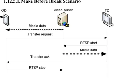
10.3.4. Scenario Make Before Break ...145
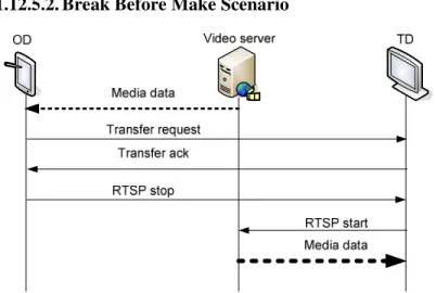
10.3.5. Scenario Break Before Make ...145
10.3.6. Renégociation des paramètres de la qualité de service ...146
10.4. Analyse des protocoles de mobilité sur IP ...147
10.5. Mécanisme collaboratif de handover ...148
10.5.1. Limitations de FMIPv6 ...149
10.5.2. Media Independent Handover ...150
10.5.3. Procedure du Handover Collaboratif...150
10.5.4. Simulation ...152
10.6. Maximisation du mode predictif de FMIPv6 ...154
10.7. Mobilité dans l’IMS ...155
10.8. Comparaison des variantes MIP...156
10.8.1. Resultats numériques...157
10.8.2. Discussion ...158
List of Figures
Figure 1: Cellular IP operation ... 19
Figure 2: IDMP architecture ... 20
Figure 3: Mobile IPv4... 23
Figure 4: MIPv6 route optimization with return routability ... 24
Figure 5: Hierarchical mobile IPv6 ... 25
Figure 6: Proxy Mobile IPv6 architecture ... 25
Figure 7: predictive mode (left) and reactive mode (right) ... 27
Figure 8: push mode and pull mode in session mobility ... 32
Figure 9: Session establishment and termination in RTSP... 34
Figure 10: SESSAMO client graphical interface... 38
Figure 11: testbed snapshot... 39
Figure 12: SESSAMO running on Nokia 770 ... 40
Figure 13: SESSAMO timing ... 40
Figure 14: make before break scenario... 42
Figure 15: break before make scenario... 43
Figure 16: Concept of MPEG-21 DIA... 45
Figure 17: Example of SDPng file [52] ... 49
Figure 18: Classical QoS negotiation procedure ... 49
Figure 19: Remote control QoS negotiation ... 50
Figure 20: Session mobility with QoS renegotiation... 50
Figure 21: Message flow of renegotiation process ... 51
Figure 22: Mobility procedure... 55
Figure 23: MIH function... 67
Figure 24: Mobility scenario... 71
Figure 25: MIH-FMIPV6 message exchange... 72
Figure 26: Remote MIH subscription and indication ... 72
Figure 28: packet loss vs PAR-NAR distance for different buffer sizes ...75
Figure 29: Buffer size vs handover delay (DMN-AR =15ms) ...76
Figure 30: Handover delay versus LGD coefficient ...78
Figure 31: Buffer size versus LGD coefficient ...79
Figure 32: Packet loss versus LGD coefficient...79
Figure 33: Ping pong avoidance Algorithm ...80
Figure 34: FBack forwarding ...85
Figure 35: New MN state machine ...86
Figure 36: Transition state diagram of FMIPv6 retransmission ...88
Figure 37: Number of retransmissions versus estimated LGD-LD time ...89
Figure 38: Retransmission probability versus frame error rate...90
Figure 39: IMS layers...93
Figure 40: Interworking architecture in IMS ...96
Figure 41: IS integration into IMS ...99
Figure 42: Selected handover message exchange ...102
Figure 43: The proposed hybrid handover mechanism...103
Figure 44: Handover delay vs UE-AR delay ...108
Figure 45: Handover delay vs UE-HA delay ...108
Figure 46: Packet loss vs application bit rate...109
Figure 47: delays between different entities ...114
Figure 48: MIPv6 bidirectional tunneling...115
Figure 49: MIPv6 route optimization...115
Figure 50: HMIPv6 inter domain mobility and route optimization ...116
Figure 51: FMIPv6 operation modes (predictive left, reactive right) ...116
Figure 52: Protocol operation delay vs NAR-HA delay ...120
Figure 53: Protocol operation delay vs PAR-NAR delay ...121
List of Tables
Table1: traffic classification in IEEE802.11e... 13
Table 2: traffic classification in WIMAX... 14
Table 3: traffic classification in UMTS ... 14
Table 4: mapping of QoS classes... 15
Table 5: Characteristics of testbed elements... 39
Table 6: make before break results ... 42
Table 7: break before make results ... 43
Table 8: summarizing table... 62
Table 9: list of media independent link events ... 68
Table 10: list of media independent link commands... 68
Table 11: simulation parameters... 77
Table 12: FMIPv6 messages size... 87
Table 13: incremental interworking scenarios... 95
Table 14: Notation table ... 106
Table 15: Simulation values ... 119
Chapter 1: Introduction
I
NTRODUCTION
Mobile and wireless communication networks have known a tremendous progress and expansion in the last few years. The fourth generation telecommunication system intends to provide a broadband wireless access to users anytime and anywhere. 4G users have the possibility to use different access network technologies from wide range to wireless local area networks (WLAN) like WIFI. The low cost of deployment and exploitation of WLANs makes them very attractive to service providers and customers. Currently France is among the countries that have a big number of deployed public WIFI access points with more than 30000 access points in 2010 [1]. Therefore, it occupies the third place after USA and china. This number does not take into account the shared connection done over the box offered by certain Internet Service Provider to their customers to enjoy internet connection when they are away from home (ex: “Free WiFi”, “Neuf WiFi”). The total number of public WiFi access points deployed in the world reaches 310000 in 2010 according to the same study, with a growth rate of 20%. In parallel to network development, mobile devices too know a complete transformation. Mobile phones, personal data assistant (PDA), Internet tablets, laptops…etc, acquire more and more hardware capabilities in terms of processing speed, memory space, communication interfaces and storage space. These capabilities allow mobile devices not only to communicate through different network technologies, but also to choose the most convenient one in case of several available networks; this latter characteristic is known as Always Best Connected (ABC). This means that at any time the mobile should be connected to the best available network. “Best” can refer to many criterions such as cost, bit rate, user preferences…etc. The mobile should decide which network will meet requirements of its applications at a given moment. Moreover, the user can even choose the right device to use depending on his situation. Transferring the current session between different terminals gives o high degree of liberty to the user and realizes a real service ubiquity. Nevertheless, the coexistence of multiple access network technologies raises the problem of interworking and mobility management
across them. Fortunately, the wide use of IP in all access and core networks makes it possible for the users to roam between different access networks while enjoying their services. However, the growing of multimedia and real-time applications usage by internet customers imposes additional constraints to mobility management protocols. Such kind of application requires a great attention to maintain the same level of quality of service. For example, in real-time applications, handover delay should be kept as short as possible to guarantee seamless service continuity.
1.1. Problem Statement
Mobility management in IP networks is gaining more and more interest from research community and service providers. The reason for this interest is the emergence of new advanced technologies in both access networks and mobile devices. From the one hand, wireless access networks are in a constant progress in terms of offered bandwidth and quality of service provisioning. On the other hand, mobile devices have known a tremendous development in terms of hardware and software capabilities which allow them to perform more complicated tasks rather than just making a phone call as the early invented mobile phones. Nevertheless, the new applications are no more based on circuit switched networks since IP has proved to be a convincing protocol for interworking between different networks and hence, adopted by the community as the protocol of infrastructure convergence and service integration. Therefore, many service providers converted there core networks to be operable on IP, and the new services are IP based as well. Voice over IP (VoIP) and IPTV are the most successful IP based services provided by many operators as part of their quadruple play service (i.e. internet, telephony, TV and mobility). Nonetheless, mobility here is limited to the access technology that the operator has chosen to carry the service on. In other words mobility is managed in a very controlled way. This restriction tightens the liberty of the user in choosing the access network he/she prefers and excludes the possibility of coexistence with other technologies even belonging to the same operator. For example, a user who is using his mobile phone to watch a TV program using 3G network would prefer to take advantage of a WIFI hot spot connection when in airport waiting room to enjoy a better quality with lower cost. Roaming between heterogeneous networks without any
Chapter 1: Introduction
interruption in the current session is a challenging task; especially with the real time character of the ongoing communication. Such task is complicated because of two reasons: i) changing access interface requires an intervention from the user since the network can only ensure horizontal handovers if supported. ii) The second reason is the inner problem of IP address function duality; the connection shall break if the IP address changes during the session. Moreover, new services should be created for session mobility support. In other words, in order to make session transfer between different terminals, new mechanisms should be defined and supported by both terminal and network.
1.2. Motivation
Continuity of service is the most important challenge that operator should face in order to offer ubiquitous service. If network heterogeneity is beneficial from user point of view, it complicates more the task for the service provider. On the one hand, solving service continuity problem will allow the operators to diversify their access network and take advantage of low cost infrastructure while maintaining the same level of QoS. On the other hand they will grant more flexibility for users to choose their favorite network or even transport the current session to a different terminal with better hardware capabilities.
The need of supporting service continuity is particularly important in applications that have certain continuity in time. For example web browsing is less stringent to service continuity since it is a discontinuous application: the user requests a web page and waits for the answer then starts reading the displayed information. At the opposite, when the application takes place for a while such in case of file download or video streaming the continuity of the service is obligatory otherwise the service will stop. The way mobility is supported is again related to the application it self. The user will not be affected by a high handover delay in case of file download since the result is not perceptible until completion of the download. On the contrary, any excessive delay in achieving the required mobility operation will affect the quality of delay sensitive applications like video streaming. Although many works have been conducted in the area of mobility, still problems are not completely solved.
1.3. Contributions
In this thesis we address the problem of service continuity in heterogeneous networks from two perspectives: session mobility and terminal mobility. Although these mobility services have the same purpose which is assuring service continuity when changing the terminal or the access network, but each technique has its own challenges and constraints.
1.3.1. Session Mobility
A new signaling protocol has been proposed for session mobility support between different terminals. The protocol has been implemented for video streaming scenario and evaluated in a testbed. In this context, we address also the problem of media adaptation especially renegotiation of QoS parameters since session might be transferred to a new terminal with different capabilities than the original one. QoS renegotiation can take place in either session transfer or during the session in the same terminal when change in some internal parameters occurs. Change in such parameters affects the quality of experience of the user if no measures are taken to adapt the media accordingly.
1.3.2. Terminal Mobility
Contribution 1:After studying the state of the art related to mobility techniques and protocols, we made a classification of terminal mobility protocols over IP in terms of operation steps. These steps are summed up in four major sub-operations that are not necessarily present in all mobility protocols. This classification is particularly interesting in the analysis and diagnosis of any mobility protocol and help in designing new protocols.
Contribution 2:
We propose a new handover mechanism using the new standard IEEE802.21 together with Fast handover for mobile IPv6. This scheme is different from the classical paradigms which are mobile initiated and network initiated handovers. Actually we put the mobile and the network in collaboration relationship and the result is a new paradigm: mobile initiated-network terminated handover.
Chapter 1: Introduction
Contribution 3:
We tackle the operation mode of FMIPv6 in order to maximize the probability of its predictive mode. This contribution can be considered as a continuation of the previous one. When the previous contribution is more based on layer 2 mechanisms to improve the handover performance, this one bring enhancement to the mobility protocol itself to maximize the probability of a successful proactive handover
Contribution 4:
In the context of IMS we propose a new hybrid mobility management protocol based on both network layer and application layer mobility protocols. This approach avoids redundancy of functionality and network entities. In addition it shows better results compared to the classical approaches. Actually this is one of the direct results of the mobility analysis in IMS under the methodology made in contribution 1. Therefore we bring the missing part in mobility operation without making any redundancy.
Contribution 5:
We conduct a comparison study of mobile IP variants in a vertical handover scenario. This work came from the fact that new protocols claim improving performance of handover. If this is true for horizontal handovers it is not always true in case of vertical handover. Through this study we show that multi interface users can perform seamless handovers with classical mobility protocols better than sophisticated ones.
1.4. Structure of The Thesis
Chapter 2: this chapter is devoted to the state of the art of both access network technologies and mobility mechanisms. It gives an overview of nowadays wireless access networks belonging to the different standard bodies. Afterwards, a number of mobility mechanisms and protocols are investigated. They are classified to layer 2 mechanisms, layer 3 mechanisms and upper layer mechanisms.
Chapter 3: in this chapter we tackle session mobility issue. This chapter is divided in two parts. The first part presents the proposed session mobility protocol “SESSAMO”. This lightweight peer to peer protocol is designed for session mobility in video streaming. Performance evaluation of the new signalling protocol is conducted
through a testbed. The second part treats the problem resulting from the mechanism of session transfer which is media adaptation. A mechanism of renegotiating the new QoS parameters depending on the capabilities of each terminal is proposed. It is based on SDPng and MPEG21 standards. In the same perspective we extend the use of renegotiation mechanism to adapt the media within the same terminal when a change of capabilities occurs during the session.
Chapter 4: after an overview of mobility protocols we draw some conclusions from the way most of IP mobility protocols work. Actually, any mobility management protocol operating in network layer, transport layer or application layer follows more or less the same sub-operations to achieve seamless transitions. In this chapter we enumerate these steps and give a recapitulation of most known mobility protocols following the defined steps.
Chapter 5: in this chapter a new handover mechanism is presented and evaluated. Based on collaboration between the mobile node and the network, this scheme allows a fast handover with minimum buffered packets. MIH is used in efficient manner with FMIPv6 to perform intelligent handovers for both heterogeneous and homogeneous networks. The choice of MIH comes from its independence regarding access network technology and its manageability by upper layers, particularly FMIPv6. A theoretical study is conducted in order to compare the performance of the new scheme with the classical ones. A set of simulations are executed as well in network simulator 2. Simulation results confirm the theoretical ones.
Chapter 6: here is yet another improvement to the previous handover process. But this time it concerns FMIPv6 operation itself. It seems that predictive mode is tied to the result of FBACK message which should be received by the mobile node in the old link; otherwise, the reactive mode is activated. In order to avoid this mode we propose to forward the FBACK message to the new location of mobile node through the established tunnel. Therefore the only case FMIPv6 operates in the reactive mode is when the fast binding update is not received correctly by the old access router. We show through analytical study that this small modification in FMIPv6 protocol has a good effect on maximizing the probability of predictive mode success.
Chapter 1: Introduction
Chapter 7: in this chapter mobility in IMS is tackled. As one of IMS purposes is to provide access network independent services, the question of service continuity between heterogeneous network technologies is important but still unsolved. We first analysed the existing signalling protocols within IMS and than deduced that the missing part towards a seamless handover is the handover smoothing step as we stated in the classification done in chapter 4. Then we propose to use FMIPv6 to perform the missing operation. Thus we use two mobility protocols: SIP at the application layer and FMIPv6 at the network layer. This mechanism does not only avoid redundancy in the network but improve the performance of the handover as well. Through an analytical study we show the advantages of our proposal over previous proposed solutions.
Chapter 8: in this chapter we present a comparative study of mobile IP variants in vertical handover. We demonstrate through this comparison that the choice of the best mobility protocol is not obvious as it might appear. In fact, having multiple interfaces, the mobile node can perform faster handovers with the conventional MIPv6 than FMIPv6. We show that the choice of the best variant of mobile IP depends on certain parameters. We finally give some guidelines that should help in choosing the most convenient mobility protocol.
S
TATE OF THE ART
:
WIRELESS ACCESS
NETWORKS AND MOBILITY
PROTOCOLS
This chapter is divided in two parts: the first part gives an overview of the most known access technologies from different standard bodies (i.e. IEEE family and ITU-T family). The second part investigates legacy mobility protocols from different perspectives. Mobility protocols are classified to micro and macro mobility protocols following their administrative range. Macro mobility protocols in their turn are classified following the layer at which they operate.
1.5. Overview of Access Network Technologies
1.5.1. IEEE Family
1.5.1.1. IEEE802.11Wireless local area networks (WLAN) have gained a big success in the last decade. This success is due to the easy deployment of this type of networks and its low cost compared to wired solutions. Moreover, the offered bandwidth in such network is still increasing with the improvement of modulation schemes and the use of smart antennas along with advanced error correction schemes. From 802.11b to 802.11n, the bit rate passed from few mega bits per second to several hundreds. Hereafter we give an overview of the famous IEEE 802.11 releases.
1.5.1.2. IEEE802.11b
802.11b [2] is the first standardized WLAN technology operating in the 2,4GHz unlicensed band. The bandwidth is divided into channels of 22MHz. The physical layer uses Direct Sequence Spread Spectrum technique and Binary Phase Shift Keying (BPSK), Differential Quadrature Phase Shift Keying (DQPSK), and Complementary Code Keying (CCK) as modulation schemes for 1Mbps, 2Mbps and (5Mbps, 11Mbps)
Chapter 2: State of the art
bit rates respectively. The medium access control is based on carrier sense multiple access with collision avoidance (CSMA/CA).
1.5.1.3. IEEE802.11a
IEEE 802.11a [3] is an amendment to 802.11 standard which operates in the 5GHz licensed band. It was designed for higher bandwidth applications than those provided by IEEE 802.11b. The maximal offered bit rate is 54Mbps using orthogonal frequency division multiplexing (OFDM). Modulation schemes start from BPSK for bit rate of 6Mbps and ends with 64-QAM for 54Mbps bit rate.
1.5.1.4. IEEE802.11g
The goal of 802.11g [4] was to provide a high throughput in the 2,4GHz band while maintaining compatibility with IEEE 802.11b. The resulting standard provides optional data rates of up to 54Mbps, and backwards compatibility with 802.11b devices to protect investments in legacy WLAN installations. It uses OFDM (the same technology used in 802.11a but in the spectrum of 802.11b) and CCK.
1.5.1.5. IEEE802.11n
The goal of the IEEE802.11n standard [5] is to increase the peak throughput, making data flow as fast as possible. The bit rate is up to 600Mbps using 40 MHz channel. The IEEE802.11n standard group makes use of Multiple-Input/Multiple-Output (MIMO) and OFDM in several configurations and provides also backwards compatibility with already installed systems in the same frequency.
1.5.1.6. IEEE802.16
The IEEE 802.16 family was originally designed to provide fixed broadband wireless access for residential and enterprise use in a point-to-multipoint (PMP) architecture. Allowing high bandwidth and rapid deployment of wireless systems, the IEEE 802.16 was immediately recognized as an interesting alternative to the conventional broadband access solutions like Digital Subscriber Line (xDSL) and Fiber To The Home (FTTH), especially in rural areas and developing countries that suffer from the lack of telephony infrastructure. Simple maintenance, scalability and speed of installation will offer better revenue for service providers.
1.5.1.7. IEEE802.16d
Also known as fixed WiMAX [7], it was approved as an upgrade to the IEEE 802.16a [8] standard. The design of a Non Line Of Sight (NLOS) system drove the design of its physical layer, which operates in the 2-11 GHz range. The channel bandwidth is variable from 1.25MHz to 20MHz, which uses 256-carrier OFDM scheme and grants access to different subscriber stations (SS) using Time-Division Multiple Access (TDMA) method. The standard supports multiple modulation levels, including BPSK, Quadrature Phase Shift Keying (QPSK), 16-Quadrature Amplitude Modulation (QAM) and 64-QAM. The modulation in the same sector is adaptive and allows subscribers to adjust the channel modulation scheme according to Signal to Noise Ratio (SNR) of the radio link. When the SNR is good the system can switch to the highest throughput modulation (ex 64-QAM). If fading occurs, the system can shift to a lower throughput modulation without dropping the connection.
1.5.1.8. IEEE802.16e
IEEE 802.16e [9] is the mobile version of WIMAX, it is intended to enable a single base station to support both fixed and mobile broadband wireless access. It provides high data rate Wireless Metropolitan Area Network (WMAN). This standard employs a scalable OFDMA system with 2048-carrier, which can scale the Fast Fourier Transform (FFT) size depending on the channel conditions. As IEEE 802.16e supports mobility, it must cope with two problems not faced by the previous standards: Power Saving and Handover. Mobile WIMAX uses OFDMA. Resources are granted to SS by assigning different subsets of carriers in different time slots.
1.5.1.9. WPAN Family
Wireless personal area networks (WPANs) are focused on a very limited range that can reach several meters. It is called personal because it concerns only the space around a single person or object. The purpose of WPAN standards is to define networks with low-cost, low power, short range and very small size. The IEEE 802.15 working group has defined three classes of WPANs that are differentiated by data rate, battery drain and quality of service (QoS). The high data rate WPAN (IEEE 802.15.3) [10] is suitable for multi-media applications that require very high QoS. Medium rate WPANs
Chapter 2: State of the art
(IEEE 802.15.1/Blueetooth) will handle a variety of tasks ranging from cell phones to PDA communications and have QoS features suitable for voice communications. The low rate WPANs (IEEE 802.15.4/LR-WPAN) [11] is intended to serve a set of industrial, residential and medical applications with very low power consumption and cost requirement not considered by the other WPANs and with low needs for data rate and QoS. The low data rate enables the LR-WPAN to consume very little power. ZigBee is an example of the IEEE802.15.4 that is used in multiple sensor applications.
For these devices to interoperate and communicate over IP networks, a common packet format must be defined to encapsulate layer 3 protocols. Bluetooth Network Encapsulation Protocol (BNEP) [13] encapsulates packets from various networking protocols, which are transported directly over the Bluetooth Logical Link Control and Adaptation Layer Protocol (L2CAP) [14]
1.5.2. Mobile Network Systems
1.5.2.1. 1GThe first commercial cellular network was the Nordic mobile telephone (NMT) deployed in Scandinavian countries in 1981, followed by the advanced mobile phone service (AMPS) in USA in 1983. The European system was known as total access communication system (TACS). These analog wireless systems are referred to as first generation or 1G. They use FDMA as medium access scheme by allocating a 30KHz wide channel for each user.
1.5.2.2. 2G
The need for proposing mobile service to wide number of customers pushed the use of digital system instead of analog one. Hence the global system for mobile communication (GSM) was developed by the European Telecommunications Standard Institute (ETSI), whereas, in North America an equivalent system was developed under the name of IS-95 CDMA known also as cdmaone. 2G systems have known the introduction of the frequency plan which is the reuse pattern of the frequency used in the cells as long as they are not adjacent. GSM system is based on time division multiple access (TDMA) with carrier bands of 200KHz whereas IS-95 system use code division multiple access CDMA.
General Packet Radio Service (GPRS) is the support of data services developed by ETSI. It is referred to as 2.5G cellular system. It defines a packet transmission system that overlays GSM and interworks with internet. A GPRS terminal is assigned an IP address and charged on the basis of transferred data. GPRS can reach a bit rate of 115kpbs by allocating the eight GSM slots to transmit or receive data packets. Data traffic and voice traffic are split by the Base Station Controller (BSC). On the one hand, it sends data packets to the Serving GPRS Support Node (SGSN) and routed afterwards toward packet data network via the Gateway GPRS Support Node (GGSN). On the other hand, voice communications are routed to the circuit switched network via the Mobile service Switching Center (MSC). An enhancement of the data rate of GSM/GPRS consists of changing the modulation scheme from Gaussian Minimum Shift Keying (GMSK) to 8 Phase Shift Keying (8-PSK). The resulting product is called Enhanced Data Rates for GSM Evolution (EDGE). However, the maximum offered rate is only 384kbps which keeps EDGE in the 2.5G category [21].
1.5.2.3. 3G
The evolution towards third generation cellular system was driven by the need of high bit rate and quality of service in order to serve multimedia content like video. Characteristics and requirement of 3G systems are specified in the ITU project called International Mobile Telephony 2000 (IMT-2000)
.
The goal of IMT-2000 is to have one worldwide standard and a common frequency band with a maximum data rate of 2Mbps. Two standards answered the requirements of ITM-2000: UMTS and CDMA2000. Universal Mobile Telecommunications System (UMTS) is the evolution of GSM system managed by third Generation Partnership Project 3GPP. cdmaone evolution has led to CDMA2000 which is managed by the 3GPP2 standard body. Newer standards surpass the requirements of IMT-2000 and are referred to as 3.5G and 3.75G like High Speed Downlink Packet Access (HSDPA) and High Speed Uplink Packet Access (HSUPA) respectively.
Chapter 2: State of the art
Long Term Evolution (LTE) and mobile WIMAX are considered as pre-4G technologies or 3.9G. In spite of the high service level provided by these technologies, they offer less than what is expected for 4G networks.
1.5.2.4. 4G
ITU has defined in 2002 a new vision for future mobile system called IMT-advanced as requirements for the fourth generation. 4G aims to provide high quality multimedia applications to mobile and fixed terminals. The targeted data rates are 100Mbps in high mobility and 1Gbps for fixed access. ITU has received two proposals that are candidates for IMT-advanced [15]: 802.16m from IEEE and LTE-advanced from 3GPP. These standards are still in progress and should be finalized by 2012.
1.5.3. QoS Provisioning in Wireless Access Networks
1.5.3.1. IEEE 802.11eIEEE 802.11e [6] is an amendment to 802.11 standard introducing quality of service provisioning for different types of traffic in particular VoIP, video, best effort and background traffic. An enhancement is made to the basic Distributed Contention Function (DCF) by defining different behavior for backoff timer and transmission operation time in order to provide the needed resources for high priority traffic. Enhanced Distributed Channel Access (EDCA) defines four access categories (ACs) with different priorities depending on the application as listed in Table1.
Table1: traffic classification in IEEE802.11e
Priority Access Category designation
1-2 AC_BK Background
0-3 AC_BE Best effort
4-5 AC_VI Video
6-7 AC_VO Voice
1.5.3.2. QoS in 802.16
QoS is an inherent feature of WIMAX. Scheduling mechanisms are implemented in both base station and mobile terminal to match QoS requirement of the application to
the available time slots and sub carriers. In the uplink, the allocation of the needed resources is done accurately thanks to bandwidth request/bandwidth grant paradigm prior to data transmission. Five QoS categories are defined following the requirements of the application; these categories are listed in Table 2.
Table 2: traffic classification in WIMAX
Class of service description Type of application
Best Effort
(BE) Basic service with no guaranty for packet delivery Web email, browsing, non
Real-Time Polling service
(nRTPS)
Terminals are polled before allocating bandwidth with no latency constraints File download (FTP) Real-Time Polling Service (RTPS)
Terminals are polled before allocating requested bandwidth and packets should leave the network within certain latency
Video streaming (MPEG) extended Real-Time Polling Service (eRTPS)
This method is in midway between UGS and RTPS that matches better requirements of VoIP with silence suppression
Voice over IP with silence suppression
Unsolicited Grant Service (UGS)
Bandwidth is granted without prior
solicitation Voice video conferencing over IP,
1.5.3.3. QoS in UMTS
3G systems introduce new IP-based services for mobile users. Some of the new services such as video streaming applications need certain level of QoS in order to provide acceptable quality of experience for the user. 3GPP has released special technical specification [16] for QoS support in UMTS. In this specification, five QoS classes have been defined (see Table 3).
Table 3: traffic classification in UMTS
Traffic class Characteristics Type of application
Conversational class
Preserve time relation between information entities of the stream with stringent and low delay
Chapter 2: State of the art
Streaming class Preserve time relation between
information entities of the stream Video streaming Interactive class Request response pattern
Preserve payload content
Web browsing Background class Destination is not expecting data
within a certain time Preserve payload content
Emails ,background download
1.5.3.4. QoS Mapping in Heterogeneous Environment
It is very important to guaranty the same QoS level for the user when roaming between heterogeneous networks. The absence of such support will affect the quality of experience of the user. This task is not simple since each network has its own definition and categorization of service classes as it has been shown in the above paragraphs. Though, an approximation of the QoS level can be made by mapping service classes from each network technology according to the served application. Table 4 gives the proposed mapping for UMTS, WIMAX and 802.11e standards.
Table 4: mapping of QoS classes
Application type UMTS 802.16 802.11e
Voice Conversational
class
UGS AC_VO
Video Streaming class RTPS AC_VI
Web browsing, file download
Interactive class Best effort, nRTPS
AC_BE Background traffic Background class Best effort AC_BK
1.6. Overview of Mobility Mechanisms
1.6.1. Types of Mobility
There are several types of mobility following the action taken by the user and the use case. Some mobility types are considered as an extra service while others are indispensable. Hereafter, the four main mobility types are introduced.
1.6.1.1. Personal Mobility
We talk about personal mobility when a single user is located at different terminals using the same logical address. Two cases are possible: one address for many potential terminals and many addresses reaching one terminal. Mapping between the different terminals and the logical address may need a dedicated server. An example of such server is the SIP registrar which maps the URI to the different IP addresses. If a user would like to be reachable on a mobile phone, a PC and a wireless device, he/she may use these devices either at the same time or alternate between them.
1.6.1.2. Service Mobility
Service mobility allows users to maintain access to their services while moving or changing devices and service providers. Services like address books, call logs or presence service can be maintained in the new location of the user. Service mobility adds certain difficulties for home service provider such as media adaptation and QoS provisioning in the new network in order to maintain service delivery at an acceptable level. This kind of mobility needs prior agreement between service providers. It should also be possible to update and customize these service definitions from the new location (new terminal or network).
1.6.1.3. Terminal Mobility
This is the most considered type of mobility in research since it is a mandatory service in wireless networks. Terminal mobility allows a device to move between different networks while continuing to communicate with its corresponding peers. Terminal mobility management protocols can intervene in different levels in the protocol stack in order to ensure uninterrupted service. Several issues should be faced by the terminal mobility protocols in order to keep acceptable perceived quality of experience regarding the ongoing communication.
1.6.1.4. Session Mobility
Session mobility allows a user to maintain a media session while changing terminals. For example, a user watching a video film in a laptop may want to continue the session in his high definition screen. Here again, media adaptation should be supported by the content provider, otherwise the QoS of the media will be affected.
Chapter 2: State of the art
Another scenario of session mobility is when the user wants to split the media to be played in different devices, for example, playing the audio stream in a speaker phone and the video stream in a video projector.
1.6.2. Layer 2 Mechanisms
Layer 2 mobility management consists mainly of ensuring access to network resources in the target network.
1.6.2.1. Mobility in Mobile Systems
Handover management in GSM networks is known as mobile-assisted handover (MAHO) because it is handled entirely by the network. More specifically the BSC and MSC are in charge of this task. When the mobile moves from one BTS to another within the same BSC the handover coordination is done by the BSC. In the case this handover is done towards another BTS which is under control of a different BSC, the handover is coordinated by the MSC. Continuous signal measurements are collected by the BSC and MSC and used in deciding which mobile should perform the handover and which cell it should handover to.
1.6.2.2. IEEE 802.11r
This standard specifies fast Basic Service Set (BSS) transitions. The main target of the IEEE 802.11r standard [17] is to reduce handoff time in order to avoid connectivity failures and packet losses while users move from a serving Access Point (AP) to a target AP. This handoff time is due to the re-authentication process that occurs in the target AP. IEEE 802.11r avoids the re-authentication process. This is especially relevant for real time applications. Coordination between serving AP and target AP takes place before traffic is routed between them.
1.6.2.3. Mobile WIMAX
Handover is handled in mobile WIMAX by using MAC messages. Various handover strategies are defined [18].
• Hard handoff (HHO): in this handoff method, the mobile station breaks contact with the serving base station before making connection with the new one. This
approach is a break-before-make approach but the handover delay is kept less than 50 ms.
• Fast base station switching (FBSS): this is a soft handover method where the mobile station is in contact with all active base stations within its coverage called “active set”. When the mobile decides to change its serving base station or “anchor base station” it sends a message in a special channel called channel quality indicator. This method requires a perfect synchronization between base stations.
• Macro diversity handover (MHDO): in this method the handover is made more seamlessly than FBSS because the mobile has simultaneous communication with all base stations of the active set.
1.6.3. Layer 3 Mechanisms
Mobility is an intrinsic issue of IP protocol. This problem comes from the fact that the design of TCP/IP stack gives two roles to the IP address simultaneously. The first role is the localization. Therefore, any node in internet is reachable with its IP address which appears in the destination field of the packet. As the internet is organized in hierarchical structure and the routing protocol uses principally the network address part of the IP address to decide which route to follow, it is not acceptable for a node to have an IP address which is not homogeneous with its sub-network. Otherwise, the packet destined to this node will never be delivered. The second role of IP address is the identification of the application, especially when using TCP as transport protocol. Actually every application uses the couple (IP address, port number) as unique identifier for the end to end communication. Any change in one of these two parameters leads to a breaking in the application flow. Discussion about the duality of the IP address has been addressed during the specification of IPv6, but the IETF members did not succeed in separating the localization from the identification in IPv6. Although some proposals try to overcome this problem like Locator/ID Separation Protocol (LISP) [19] and Host Identity Protocol (HIP) [20], they are not widely deployed. Instead of treating the source of the problem, the whole research community is concerned about finding solutions for
Chapter 2: State of the art
the symptoms. In the following we give an overview of the most known mobility management schemes in the network layer.
1.6.3.1. Micro Mobility
When a terminal changes frequently its subnet within the same domain we talk about micro mobility.
1.6.3.1.1. Cellular IP
Cellular IP [22] inherits cellular principles used in cellular networks like GSM for mobility management, but implements them around the IP paradigm. Cellular IP access networks require minimal configuration, therefore, easing the deployment and management of wireless access networks. The major component of Cellular IP access networks is the base station which acts as wireless access point and router of IP packets. Base stations are built on a regular IP forwarding engine with the exception that IP routing is replaced by Cellular IP routing with location management support. Mobile hosts attached to the access network use the IP address of the gateway as their care-of address. Figure 1 illustrates the path taken by packets addressed to the mobile node. All packets destined to the MN reach first the gateway from which they are routed through the base stations to their respective IP address.
Figure 1: Cellular IP operation
In Cellular IP, location management and handoff support are integrated with routing. To minimize control messaging, regular data packets transmitted by mobile
hosts are used to refresh host location information. Uplink packets are routed from a mobile host to the gateway on a hop-by-hop basis. The path taken by these packets is cached by all intermediate base stations. To route downlink packets, the path used by packets recently transmitted from the mobile host is reversed. When the mobile host has no data to transmit, it sends small, special IP packets toward the gateway to maintain its downlink routing state.
1.6.3.1.2. Intradomain Mobility Management Protocol
Figure 2: IDMP architecture
Intradomain mobility management protocol (IDMP) [23] is designed to work as a standalone solution. As illustrated in the Figure 2, IDMP architecture relies on two network entities: Mobility Agent (MA) and Subnet Agent (SA). MA is responsible for mobility management in the whole domain and SA is in charge of mobility management within the subnet.
In IDMP, the MN acquires two types of CoA: Local care-of address (LCoA) which identifies the MN’s attachment to the subnet and Global care-of address (GCoA). The MN should inform its MA about any change in the LCoA. While MN updates its GCoA only if it changes the domain. All packets addressed to the MN are forwarded to the GCoA where they are intercepted by the MA. MA then encapsulates these packets to the MN’s current LCoA.
Chapter 2: State of the art
IDMP defines also a fast handoff procedure based on layer 2 indicators. In order to minimize service disruption the MN generates a movement imminent message to the MA. Upon receiving this message, MA multicasts the packets destined to the MN towards a set of neighboring base stations. Packets are buffered in the BSs until attachment of the MN to the new subnet, and then they are immediately forwarded.
1.6.3.1.3. HAWAII
Mobile IP results in high overhead when the mobile is changing its subnet frequently because the MN should update its HA each time it acquires a new CoA. Moreover when QoS is provided by the network, the QoS reservation from HA to FA has to be reestablished even if most of the path remains unchanged. For these reasons Handoff Aware Wireless Access Internet Infrastructure (HAWAII) [24] was introduced as a complement of mobile IP to support intradomain mobility management. It uses specialized path setup schemes which install host-based forwarding entries in specific routers to support intra-domain micro-mobility. These entries reduce mobility related disruption to user applications, and at the same time reduce the number of mobility related updates. Moreover, HAWAII simplifies quality of service support since mobile hosts retain their network address while moving within the domain.
Protocol operation is as follows: each MN has an IP address and a home domain, when moving within the same domain, MN maintains its IP address. When the MN enters into a foreign domain, the MN is assigned a co-located CoA using DHCP. Packets destined to the MN are tunneled to the CoA. They reach first the domain root router based on the subnet address of the domain and then they are forwarded over special dynamically established paths using host-based routes in routers towards the MN. Mobile IP registration is split in two parts: between MN and BS and between BS and HA. This separation helps in reducing the updates of the HA.
1.6.3.2. Macro Mobility
1.6.3.2.1. Mobile IPv4
Mobile IPv4 [25] has been introduced by IETF to deal with IP address change in access networks. It allows to all corresponding nodes that are currently in communication with
the mobile node and future correspondents to keep the same identity whatever the network to which the mobile is connected. As routing protocols in today internet are
based on network addresses, it is clear that when the mobile moves to a new subnet, routing its packets in the downlink is impossible since its address doesn’t belong to the current subnet. The idea behind MIPv4 is to hide the modification in the network layer
from the application by defining two types of addresses: i) home address which is a fixed address used as an identifier for applications and never changes wherever the MN
is located, ii) Care of Address (CoA) is a variable address used temporarily by the mobile node in the visited network. When the MN quits the home network and attaches to a foreign network, it listens to the advertisement sent by the Foreign Agent (FA) and then sends a registration to the FA which relays the request to the Home agent to check if the MN is authorized to use MIPv4 service. After verification, the FA sends a reply to the MN including the CoA to be used by the MN along its sojourn in this network. CoA in MIPv4 is of two kinds: FA-CoA and Co-located CoA. In case of FA-CoA, the MN
use the address of the FA as a CoA, where as any IP address that belongs to the sub-network can be used in case of Co-located CoA (i.e. MN’s CoA can be acquired by DHCP server). As far as the correspondent node (CN) is concerned, it continues sending
data packets to the home address as if the MN is still in the home network. These packets are intercepted by the HA and encapsulated towards the FA. Then they are
decapsulated in the FA and forwarded to the MN (see
Figure 3). In Co-located CoA the tunnel is established between the HA and the MN without passing through the FA.
Chapter 2: State of the art
Figure 3: Mobile IPv4
Limitations of MIPv4:
The main drawback of MIPv4 is its high handover delay. This delay comes from the fact that the MN should wait for advertisements of FA, and then register to the FA before the tunnel can be established and eventually forward packets. The result of such long handover delay is the loss of some data packets. Secondly routing through the HA is inefficient in case the MN is far away from the HA and leads to a high end to end delay and high overhead, this phenomena is known as triangular routing. Finally, HA is a single point of failure on which the whole system operation depends. Moreover traffic of all MNs go through the HA which can lead to bottle neck creation in the home network.
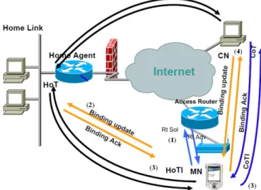
1.6.3.2.2. Mobile IPv6
Although mobile IPv6 [26] maintains the same functioning principle of the previous version, it introduced some improvements. Taking advantage from the IPv6 structure, a mobility header was defined for MIPv6 as an extension header which entails FA suppression. In addition, the route optimization is used as a fundamental support rather than an extension, and the correspondent node is updated securely by using the new return routability procedure. Moreover, neighbor discovery is used instead of address resolution protocol (ARP), thus decoupling MIPv6 from the link layer. MIPv6 operates in two modes: reverse tunneling and route optimization. In reverse tunneling
mode, the MN receives the new CoA by means of router solicitation and router advertisement, then updates its binding with the HA which creates the bidirectional tunnel.
Figure 4: MIPv6 route optimization with return routability
When route optimization is used (Figure 4), the MN should also update the CN after updating the HA. A security mechanism called return routability is introduced in the MIPv6 to secure the binding update with the CN. Home Test Init and Care-of Test messages are sent simultaneously via HA and directly to the CN respectively. Afterwards, CN and MN communicate directly without going through HA. Route optimization allows avoiding triangular routing.
1.6.3.2.3. Hierarchical Mobile IPv6
Hierarchical mobile IPv6 [28] was introduced to reduce both the amount and delay of signaling messages between the MN and the HA/CN. A new entity called Mobility Anchor Point (MAP) is introduced to maintain tracking of the MN within a defined domain using a new care of address called Regional Care-of-Address (RCoA). MN should register its RCoA within the HA when moving to another network in a different domain (see Figure 5). In case of intra-MAP mobility, the only operation that the MN should perform, is binding update (BU) of its new acquired on-Link CoA with the MAP. Data packets are tunneled twice in HA and MAP before being forwarded to the MN.
Chapter 2: State of the art
Figure 5: Hierarchical mobile IPv6
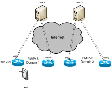
1.6.3.2.4. Proxy Mobile IPv6
MIPv6 needs the intervention of the mobile to achieve mobility operation. Network-based mobility is another approach to solve the IP mobility issue. A proxy mobility agent performs the signaling with the HA and does the mobility management on behalf of the MN. For this reason, this mobility management protocol is referred to as Proxy Mobile IPv6 (PMIPv6) [29]. PMIPv6 was recently adopted as mobility management protocol for packet data networks in 3GPP (TS 29.275) and 3GPP2 (3GPP2 X.S0057-0)
Special network entities track MN's movement, initiate the mobility signaling and set up the required routing state. These tasks are performed by two network entities: Local Mobility Anchor (LMA) and Mobile Access Gateway (MAG) (see Figure 6). LMA has the functional capabilities of the HA as defined in MIPv6. MAG is a function on the access router that manages the mobility-related signaling for a MN that is attached to its access link. It is responsible for tracking the MN's movements and signaling management with LMA on behalf of the MN. LMA being the topological anchor point for the MN home network prefix(es), receives any packets that are sent to the MN by any other node and forwards them to the MAG through a bi-directional tunnel. The MAG on the other end of the tunnel removes the outer header and forwards the packet on the access link to the MN.
1.6.3.2.5. Fast Handovers for Mobile IPv6
Latency caused by MIPv6 operation is unacceptable for real-time and throughput sensitive applications. To overcome this problem a fast handover scheme [27] was proposed by the IETF. Fast handovers for Mobile IPv6 (FMIPv6) allows the MN to anticipate the IP address acquisition and forward packets from previous access router (PAR) to new access router (NAR) during the handover. FMIPv6 relies on layer 2 triggers to warn MN that the signal strength is going down, then the MN sends a router solicitation proxy (RtsolPr) and gets a proxy router advertisement (PrRtAdv) which contains information about the neighboring cells especially (AP-ID, AR-Info). This couple contains access router's MAC and IP addresses, and the valid prefix on the interface to which the Access Point (identified by AP-ID) is attached. With this information, the MN formulates a prospective New CoA (NCoA) and sends a fast binding update (FBU) to PAR. The purpose of the FBU is to authorize PAR to bind Previous CoA (PCoA) to NCoA, so that arriving packets can be tunneled to the new location of the MN. PAR sends Handover Initiate (HI) message to carry the NCoA to the NAR which determine after a Duplicate Address Detection (DAD) whether NCoA is unique on its link interface or not. In case of address conflict, NAR assigns another address and includes it in the Hack message and the PAR in return will assign it in the FBack. After attaching to the new network, The MN sends unsolicited neighbor
Chapter 2: State of the art
announcement (UNA) immediately, so that buffered packets at NAR can be forwarded to the MN right away. The tunnel created between the two routers remains active until the MN completes the binding update with its HA and/or CN.
FMIPv6 is not tied to MIPv6 or any other protocol as it might be thought. It can assist any mobility management protocol by allowing a smooth handoff wkile the mobility protocol makes the necessary updates. Usually FMIPv6 is used with MIPv6 and PMIPv6 [30] but can also be used with upper layer protocols like SIP [31].
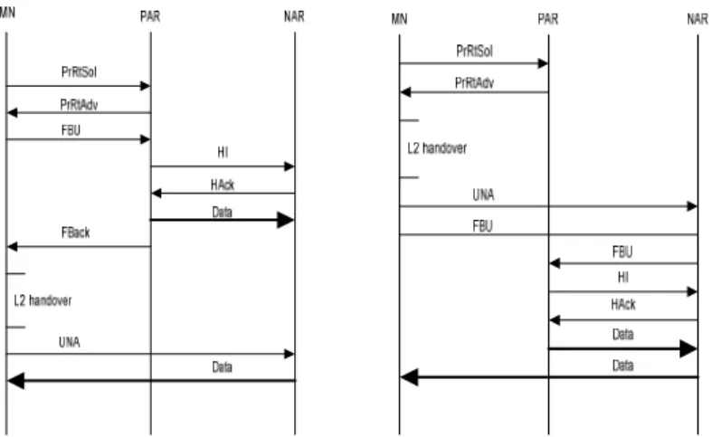
Figure 7: predictive mode (left) and reactive mode (right)
FMIPv6 is operating in two modes (see Figure 7): predictive mode when FBack is received in the previous link and reactive mode when FBack fails to attain the MN because of an unexpected link down for example. PAR starts forwarding packets through the tunnel upon receiving an acknowledgement of HI from the NAR without having any indication of FBack reception by the MN. In the case where MN does not receive the FBack because of a link down, it falls into the reactive mode and resends another FBU on the new link.
1.6.3.3. Upper Layer Mechanisms
In this section we give an overview of upper layer mobility management protocols. These protocols manage mobility in transport level or application level. At the opposite of layer 3 mechanisms, upper layers protocols get the end points more involved in the mobility operation.