HAL Id: hal-01334989
https://hal.archives-ouvertes.fr/hal-01334989
Submitted on 21 Jun 2016
HAL is a multi-disciplinary open access
archive for the deposit and dissemination of
sci-entific research documents, whether they are
pub-lished or not. The documents may come from
teaching and research institutions in France or
abroad, or from public or private research centers.
L’archive ouverte pluridisciplinaire HAL, est
destinée au dépôt et à la diffusion de documents
scientifiques de niveau recherche, publiés ou non,
émanant des établissements d’enseignement et de
recherche français ou étrangers, des laboratoires
publics ou privés.
Inductive thermography nondestructive testing applied
to carbon composite materials: multiphysics and
multiscale modeling
H.K. Bui, G Berthiau, D Trichet, G Wasselynck
To cite this version:
H.K. Bui, G Berthiau, D Trichet, G Wasselynck. Inductive thermography nondestructive testing
applied to carbon composite materials: multiphysics and multiscale modeling. 8th International
Conference on Electromagnetic Processing of Materials, Oct 2015, Cannes, France. �hal-01334989�
Inductive thermography nondestructive testing applied to carbon composite materials:
multiphysics and multiscale modeling
H. K. Bui
1, G. Berthiau
1, D. Trichet
1and G.Wasselynck
11 Institute for Research in Electrical Energy of Nantes-Atlantique (IREENA)
University of Nantes – EA CNRS 4642, CRTT, BP 406, F-44602 Saint-Nazaire Cedex, France
Corresponding author: [email protected]
Abstract
This paper present a high potential NDT technique based on electromagnetic induction and thermography method called induction thermography or eddy-current thermography applied to laminated CFRP composites. Accurate assessment of the performance of this technique requires the development and use of a specific multiphysics and multiscale computation code in which mesoscopic model is used in macroscopic scale simulations. Simulation results show that short time heating is advantageous.
Key words: CFRP composite, NDT, induction thermography, multiphysics and multiscale Modeling. Introduction
Carbon Fiber Reinforced Polymer (CFRP) Composite is widely used in the aeronautic industry due to their high strength and light weight. For example, the composite ratio in the A320 of Airbus is about 20% of the total mass and has risen to 25% in the A380 and over 50% in the A350-XWB. However, the large-scale development of these materials still requires improvement in the processes during the whole life cycle of the material (forming, assembly, quality control and recycling). Technological obstacles to be overcome are mainly related to production rate issues, process control or evaluation of material health.
At various stages of their life cycle, Non Destructive Testing (NDT) methods are often used to control the integrity state of the materials. The objectives of NDT techniques are to detect and characterize defects in the material. They play a vital role in the quality control and risk management. The main requirements for NDT techniques are: the ability to detect and discriminate the defects of various kinds, accurate evaluation of defects, fast and reliable inspection, the inspection capability for complex structures. Due to their complex natures (heterogeneity, strong anisotropy and multilayer) the detection of mesoscopic defects in CFRP composites still present problems which call for new improvement in actual NDT methods.
In the following, the principle of a new NDT technique called induction thermography is firstly presented. The development of the numerical simulation tool must deal with some modeling constraint associated to laminated CFRP composites and most encountered defects in these materials. The latter is then briefly explained. Our original multi-physics and multi-scale modeling approach is next presented. Simulation results are discussed.
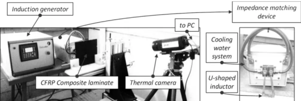
Induction thermography technique
The Fig. 1 shows the set-up of an induction thermography test bench. By induction heating principle, the workpiece is heated due to Joule effect of eddy-current. The inductor can be of arbitrary form. In this figure, a U-shaped inductor is shown. The temperature exposed to the surface of the workpiece is then measured with an infrared thermal camera. The presence of hidden or open defects can [1]:
- disturb the induced currents flow and generate intensified currents areas. - inhibit the heat diffusion in the composite.
The zone of intensified eddy-currents is correlated with hotter regions appearing around the defect whereas the presence of low thermal conductivity region in the material leads to the delayed heat flow. This double detection mechanism may enable a high defect detection capability for eddy-current thermography method. Generally, these disturbances lead to unusual distributions and temporal evolution of the temperature on the surface of the material. The latter is then processed and analyzed to detect and characterize the defects. The use of infrared camera allows for a large zone inspection in a single test. The performance of induction thermography technique depends on the used devices, of several process parameters (heating time, inductor shape, electromagnetic source frequency) and thermal signal processing methods so-called temperature contrasts [2].
Laminated CFRP composite
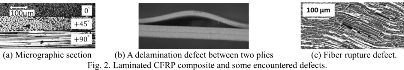
This material consists of stacks of several unidirectional plies as shown in the Fig. 2. (a). Each ply is characterized by a single fiber orientation whereas the composite material is characterized by its stacking sequence (i.e. the sequence of ply orientations).
(a) Micrographic section (b) A delamination defect between two plies (c) Fiber rupture defect. Fig. 2. Laminated CFRP composite and some encountered defects.
During the manufacturing process or operation time, several defects can occur in the CFRP. They can reduce the mechanical strength and increase the failure risk. Delamination, fiber rupture and porosity are the most commonly encountered defect types. Delamination occurs at the interface between unidirectional plies (Fig. 2. (b)). They can be induced by matrix/reinforcement disbonds that reach the interface between two plies. Fiber ruptures can occur in tension or compression when the plies are solicited in the direction of the fibers (Fig. 2. (c)). Porosity level can be expressed by the ratio of void volume to total volume of the composite. These defects are considered in mesoscopic scale, i.e. the scale of an elementary ply.
Multiphysics and multiscale modeling
CFRP material has a complex multiscale structure. The characteristic size of the microscopic scale is about 7 μm or the diameter of a carbon fiber whereas that of the mesoscopic scale is the thickness of a ply which is about 150 μm. The macroscopic scale consists of the entire laminate. Its size could be in order of some meters. Due to the large scale factor, a multiscale approach is used to simulate the CFRP behavior. Two principal steps are given as follows:
- The mesoscopic scale behavior is obtained using our original microscopic percolation model which gives a homogenized equivalent tensor of electrical conductivities of an unidirectional ply [3][4].
- The macroscopic scale behavior is modeled by means of a 3D multilayer finite element model.
Homogenization model gives three components of the electrical conductivity of a unidirectional composite ply: σ||, σ⊥
and σz which are respectively the homogenized electric conductivity in the fiber axis, perpendicular to the fiber axis and
in normal direction of ply surface (z-axis). In 3D multilayer finite element model, because a composite ply is very thin and highly anisotropic, if the laminate is meshed, it may lead to some numerical issues due to the distortion of the mesh and the strong anisotropy of constitutive law. In this case, orthogonal hexahedral finite elements are used thank to their stability and accuracy.
Moreover, induction thermography simulation model involves a coupled electromagnetic and thermal problem. The following weak electromagnetic 𝑨 − 𝜓 and nodal thermal formulations (1), (2) and (3) are used to calculate the temperature distribution in the laminate [5][6]:
∫ (𝒄𝒖𝒓𝒍𝒘𝑒 1 𝜇𝒄𝒖𝒓𝒍𝑨 + [𝝈]𝒘𝑒 𝑗𝜔(𝑨 + 𝒈𝒓𝒂𝒅𝜓)) Ω 𝑑Ω − ∫ 𝒘𝑒(𝒏 ∧ 1 𝜇𝒄𝒖𝒓𝒍𝑨) 𝛤 = ∫ 𝒘𝑒 𝑱𝑠𝑑Ω Ω (1) ∫ (𝑗𝜔[𝝈]𝒈𝒓𝒂𝒅𝑤𝑛 (𝑨 + 𝒈𝒓𝒂𝒅𝜓)) Ω𝑐 𝑑Ω = 0 (2) ∫ (𝜌𝐶𝑝 𝜕𝑇 𝜕𝑡− 𝑑𝑖𝑣[𝝀]𝒈𝒓𝒂𝒅𝑇) 𝑤𝑛 Ω𝑐 𝑑Ω = ∫ 𝑃𝑤𝑛 Ω𝑐 𝑑Ω (3)
where 𝑨 and 𝜓 are respectively the magnetic vector potential and the primitive in time of electric scalar potential, 𝑱𝑠 the
source current density, 𝑃 the electromagnetic induced power density, 𝑇 the temperature, 𝐶𝑝 the specific heat, 𝜌 the
specific mass of the material, [𝝈] and [𝝀] respectively the tensors of electrical and thermal conductivity. The edge shape function and nodal shape function are denoted by 𝒘𝑒 and 𝑤𝑛 respectively. The electrical conductivity tensor [𝝈] of the
ply i having a fiber orientation (with respect to the common 𝑂𝑥𝑦 coordinates which lie in the plan of the ply) takes the form: [ 𝜎𝑥𝑥 𝜎𝑥𝑦 0 𝜎𝑦𝑥 𝜎𝑦𝑦 0 0 0 𝜎𝑧 ] = [ 𝜎‖𝑐𝑜𝑠2 + 𝜎┴𝑠𝑖𝑛2 (𝜎‖− 𝜎┴)𝑐𝑜𝑠 𝑠𝑖𝑛 0 (𝜎‖− 𝜎┴)𝑐𝑜𝑠 𝑠𝑖𝑛 𝜎‖𝑠𝑖𝑛2 + 𝜎┴𝑐𝑜𝑠2 0 0 0 𝜎𝑧 ] (4)
It is noted that the thermal conductivity tensor [𝝀] takes the same form as the electric one. Three orthogonal components of thermal conductivity are studied in [7]. In thermal problem, only the composite domain (Ω ) is considered. In its boundary (denoted by ), the Newman type boundary condition: −[𝝀]𝜕𝑇 𝜕𝒏 = (𝑇𝛤𝑐− 𝑇) is applied. In this equation, 𝒏
is normal vector of and 𝑇 the room temperature. The exchange coefficient includes both the natural convection and radiation boundary conditions [8].
Case study
The piece to be inspected is an 8 plies composite plate with the lay-up sequence [135°/90°/45°/0°]S. The dimension of
the plate is 0.2m × 0.2m × 1mm in which the thickness of a ply is 136μm. Two defect types are introduced in a 0° ply of the piece as shown in the Fig. 3. The thickness of the defects is of 68μm or a haft of the ply one.
(a) with fiber rupture defect. (b) with delamination defect. Fig. 3. Case study configuration. Inductor dimensions: hc = 30mm, wc = 40mm.
A vertical rectangular inductor (coil) is used in this study. It is placed right above the piece and centered on it. The excitation current intensity is of 100A RMS at 1MHz.
Electromagnetic simulation results
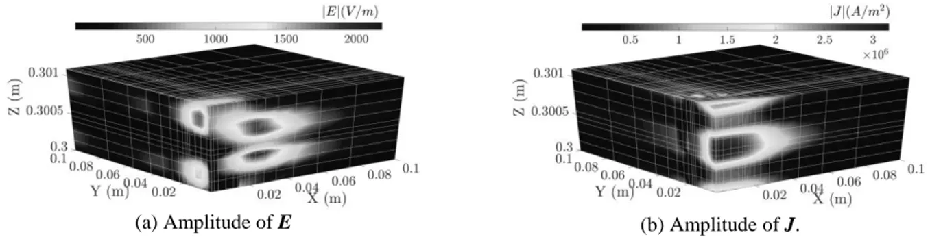
The Fig. 4 shows the distribution of electric field E and eddy-current J in the laminate in the case without defect. As can be seen, these distributions are very heterogeneous depending strongly on the lay-up sequence of the material. Hence, the precise description of induced fields in the laminated composite cannot be simulated using homogenous macroscopic model. This shows the accuracy of the presented multi-scale modeling approach.
(a) Amplitude of E (b) Amplitude of J.
Fig. 4. Distribution of induced fields in the laminated composite. A quarter of the plate (x > 0, y > 0) is shown. Defect detection by absolute contrast image
Absolute contrast (Ca) technique consists of subtraction between thermal images measured on defective piece and
healthy one [2]. The non-null contrast areas on the resulting images allow for detection of defects. The defects can be detected in transmission mode and reflection mode as well. In the reflection mode, the temperature on the surface in the inductor side of the laminate is measured whereas in the transmission mode the temperature is measured in the opposite
Inductor side
Opposite side
side (cf. Fig. 3 (b)). The choice of working mode depends on the accessibility of the infrared thermal camera.
(a) Piece with delamination
defect. Inductor side. (c) Piece with fiber rupture defect. Inductor side.
(b) Piece with delamination
defect. Opposite side. (d) Piece with fiber rupture defect. Opposite side. Fig. 5. Absolute contrast image obtained on the inductor side surface of the laminate and its opposite side. Some image of the Ca is shown in the Fig. 5. In these cases, the piece is heated during 1s and the images are calculated
at instant when the induction generator is turned off. Advantage of short time heating
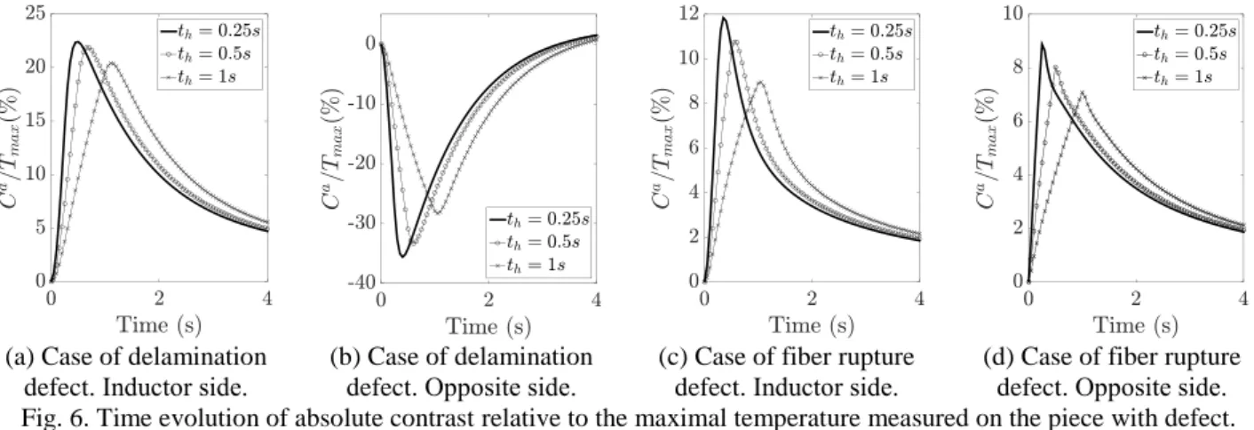
The heating duration th is a parameter to be optimized. Simulations with various heating duration are carried out with
the same excitation conditions. The temporal evolution of the absolute contrast on the middle point of the detected defective areas (Fig. 5) is calculated and compared with the maximum temperature (Tmax) measured in each case. The
Fig. 6 shows the Ca/Tmax curves for various heating durations which are respectively of 0.25s, 0.5s and 1s.
(a) Case of delamination defect. Inductor side.
(b) Case of delamination defect. Opposite side.
(c) Case of fiber rupture defect. Inductor side.
(d) Case of fiber rupture defect. Opposite side. Fig. 6. Time evolution of absolute contrast relative to the maximal temperature measured on the piece with defect. As can be seen, the defect detection is more efficient with brief heating time. However, it is also necessary to increase the temperature of the piece to deal with high noise level problem. The use of high excitation current or high frequency induction heating device is therefore recommended.
References
[1] T. Sakagami and K. Ogura (1994), JSME Int. journal. Ser. A, Mech. Mater. Eng., vol. 37, no. 4, pp. 380–388. [2] X. Maldague (2001), Theory and practice of infrared technology for nondestructive testing. John Wiley & Sons. [3] G. Wasselynck, D. Trichet, and J. Fouladgar (2013), IEEE Trans. Magn., vol. 49, no. 5, pp. 1825–1828. [4] H. K. Bui, G. Wasselynck, D. Trichet, J. Fouladgar, B. Ramdane, and G. Berthiau (2014), COMPEL Int. J.
Comput. Math. Electr. Electron. Eng., vol. 33, no. 1/2, pp. 167–180. [5] O. Bíró (1999), Comput. Methods Appl. Mech. Eng., vol. 169, pp. 391–405.
[6] J. Taler and P. Duda (2006), Solving Direct and Inverse Heat Conduction Problems, Springer. [7] C. Ageorges, L. Ye, Y. Mai, and M. Hou (2006), Compos. Part A, vol. 29A, no. 98, pp. 899–909. [8] H. K. Bui, G. Wasselynck, D. Trichet, and G. Berthiau (2015), IEEE Trans. Magn., vol. 51, no. 3.