Towards High Performance Virtual Routers
on Commodity Hardware
Norbert Egi
Lancaster University, UK[email protected]
Adam Greenhalgh
University College London, UK
[email protected]
Mark Handley
University College London, UK
[email protected]
Mickael Hoerdt
Lancaster University, UK
[email protected]
Felipe Huici
NEC Europe Ltd, Germany
[email protected]
Laurent Mathy
Lancaster University, UK
[email protected]
ABSTRACT
Modern commodity hardware architectures, with their mul-tiple multi-core CPUs and high-speed system interconnects, exhibit tremendous power. In this paper, we study perfor-mance limitations when building both software routers and software virtual routers on such systems. We show that the fundamental performance bottleneck is currently the mem-ory system, and that through careful mapping of tasks to CPU cores, we can achieve forwarding rates of 7 million minimum-sized packets per second on mid-range server-class systems, thus demonstrating the viability of software routers. We also find that current virtualisation systems, when used to provide forwarding engine virtualisation, yield aggregate performance equivalent to that of a single software router, a tenfold improvement on current virtual router platform per-formance. Finally, we identify principles for the construc-tion of high-performance software router systems on com-modity hardware, including full router virtualisation sup-port.
1.
INTRODUCTION
Over the last few years virtualisation has become a hot topic, with platforms such as Xen[1] and VMware[2] en-abling virtual machines on regular x86 PC hardware, and Intel and AMD both adding virtualisation extensions[3] to their processors. Of course, virtualisation is nothing new: IBM’s CP/CMS[4] provided virtual machine support in the late 1960s. However, only recently has PC hardware be-come powerful enough to make running multiple virtual ma-chines on one inexpensive box a practical proposition. From a server point of view, virtualisation makes a great deal of
Permission to make digital or hard copies of all or part of this work for personal or classroom use is granted without fee provided that copies are not made or distributed for profit or commercial advantage and that copies bear this notice and the full citation on the first page. To copy otherwise, to republish, to post on servers or to redistribute to lists, requires prior specific permission and/or a fee.
ACM CoNEXT 2008, December 10-12, 2008, Madrid, SPAIN Copyright 2008 ACM 978-1-60558-210-8/08/0012 ...$5.00.
sense: a single machine in a data center can support many different network servers. One of the advantages arising from this is isolation, ensuring that if a virtual server is com-promised the damage is limited and the faulty server does not exhaust all OS resources. Another clear advantage is that un-used resources from one server can be un-used by another. And perhaps most importantly, different administrators can man-age different servers on the same hardware without needing to trust each other, thus enabling many new business models. The advantages of isolation and independent administra-tion carry over to network virtualisaadministra-tion. Virtual LANs (VLANs) and Virtual Private Networks (VPNs) allow a sin-gle network to be subdivided and to have different users of the network isolated from each other. However, while most ethernet switches support VLANs, the model is that a single switch administrator configures these VLANs. While from the outside it looks like the switch is behaving as a separate switch for each VLAN, the switch itself is not virtualized in any real sense. The same is true with VPNs: an ISP might sell a VPN service, allowing a customer to interconnect his sites over the ISP’s Internet backbone, safe in the knowledge that they are isolated from other users of the public Internet. However, the customer does not get a virtual slice of the ISP’s core routers to manage as he sees fit.
Extending the idea of true virtualisation to network re-sources, and to routers in particular, seems like the natural next step. The benefits are obvious: a single virtual router platform can provide independent routing for multiple net-works in a manner that permits independent management of those networks. There are many applications for such a tech-nology. For example, within our university there is a router connected to the campus backbone that also provides rout-ing between IP subnets within our department. Should this be managed by the campus network administrators or by our department? Such petty turf wars are remarkably common-place. Virtual routers allow separate administration within a single box in a natural manner; they also enable many busi-ness models that are currently difficult.
Core 5 L1 Core 6 L1 Core 7 L1 Core 8 L1 L2 Core L1 Core 2 L1 L2 Core 3 L1 Core 4 L1 1 L2 L2 82571 82571 PCIe x8 (x4 card) 82571 82571 PCIe x8 (x4 card) 82571 82571 PCIe x4 (x4 card) South Bridge 1.3 Ghz FSB North Bridge 2 Memory Banks
Figure 1: Architecture of a Dell PowerEdge 2950
0.0 0.5 1.0 1.5 2.0 2.5 3.0 0.0 5.0 10.0 15.0 20.0 25.0
Received Packet Rate (Mpps)
Generated Packet Rate (Mpps) 2 unidirectional flows 4 unidirectional flows 6 unidirectional flows 2 bidirectional flows 4 bidirectional flows 6 bidirectional flows
(a)64-byte packets
0.0 0.2 0.4 0.6 0.8 1.0 1.2 1.4 1.6 0.0 0.5 1.0 1.5 2.0 2.5
Received Packet Rate (Mpps)
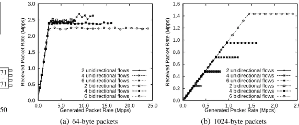
Generated Packet Rate (Mpps) 2 unidirectional flows 4 unidirectional flows 6 unidirectional flows 2 bidirectional flows 4 bidirectional flows 6 bidirectional flows (b)1024-byte packets Figure 2: One and two-way forwarding performance for a single-processor router. Mpps stands
for millions of packets per second. and enables a form of virtual network1, where the routers
are virtualized and interconnected by virtual links using tun-neling. Pushing this down into the physical infrastructure so that virtual routers are directly connected by VLAN or MPLS sliced physical links would allow an entire network to be virtualized, whether simply to allow independent man-agement or to enable whole new network architectures to be rolled out without risk of damage to existing network ser-vices. Given the difficulties faced in changing the current Internet, it seems likely that router and network virtualisa-tion could be a key enablers for Internet innovavirtualisa-tion.
For many applications of virtual routers, flexibility is cur-rently considered more important than raw speed. Indeed, while the forwarding rate reported in recent virtual router work (e.g., the rate for minimum-sized packets of roughly 700kpps in [6] or [7]) is significantly better than that origi-nally achieved in VINI [5], it is still rather low for practical applications in a real network.
On the other hand, on many occasions over the last few years, we have heard people assert that for routers to go fast, they would need dedicated forwarding hardware, with the various camps pushing the case for Network Processors, FPGAs, and various forms of offload engines; usually such pitches include graphs showing the sorry state of software forwarding. However, all low and mid-range Cisco routers still use software forwarding, so clearly the commercial world finds the performance acceptable for the sort of link speeds purchased by small and medium sized businesses.
So, can a high-performance software virtual router be rea-sonably conceived? If the goal is to enable innovation, then it would be wonderful if software routers were up to the job, because the alternatives are so much harder to work with. What then is the real story regarding software router perfor-mance?
PC hardware has moved on significantly in the last few years, and results from five years ago are now largely irrel-evant. PCI buses are no longer the serious bottleneck they once were, and multi-core CPUs promise much more
pro-1The term virtual network should not to be confused with the rather limited commercial VPN offerings.
cessing power if only we can find a way to harness it. If we want future Internet routers to be more flexible than cur-rent IP routers, then (at least at the network edges) it seems that the flexibility of software routers on cheap commodity multi-core CPUs could potentially be a huge win.
In this paper, we examine the issue of how well suited these new commodity hardware architectures are to full router virtualisation. By exploring performance limitations and their causes, we hope to scope the debate regarding this rapidly expanding area of research with some real data. Beyond this, we aim to identify principles for the design of high perfor-mance software virtual routers.
This paper is organized as follows. Section 2 investigates performance aspects of software routers in the context of multi-core commodity machines. Section 3 evaluates the various approaches to building software virtual routers, fo-cusing on issues for high forwarding performance; we con-clude in section 4.
2.
ROUTERS ON MODERN X86 SYSTEMS
Modern x86 hardware is not bereft of resources: the in-troduction of PCI Express buses and multi-core CPUs have changed the scene considerably in the last couple of years. Although we have results from quite a number of different x86 systems, for simplicity of explanation we will show re-sults only from one class of machines that typifies mid-range server-class systems; the architecture of this particular class of systems will let us tease apart some of the causes of per-formance bottlenecks.
The systems we will use are Dell PowerEdge 2950 sys-tems (Figure 1). These are relatively inexpensive servers, with two Intel quad-core CPUs. In reality, these are really two dual-core CPUs on one die, as only pairs of cores share L2 caches. Further, the system has 8GB of DDR2 667MHz memory, arranged in eight 1GB modules on a dual-channel setup. With respect to networking, the server has three quad-gigabit ethernet cards, for a total of 12 interfaces. Each of these cards has two Intel 82571EB controller chips, each of which handles two ports, and connect using 4 PCIe lanes each.
0 1 2 3 4 5 6 7 8 0 2 4 6 8 10 12
Received Packet Rate (Mpps)
Generated Packet Rate (Mpps) 1 unidirectional flow 2 unidirectional flows 3 unidirectional flows 4 unidirectional flows 5 unidirectional flows 6 unidirectional flows
(a)64-byte packets - unidirectional flows
0 1 2 3 4 5 6 7 8 0 5 10 15 20 25
Received Packet Rate (Mpps)
Generated Packet Rate (Mpps) 1 bidirectional flow 2 bidirectional flows 3 bidirectional flows 4 bidirectional flows 5 bidirectional flows 6 bidirectional flows
(b)64-byte packets - bidirectional flows
Figure 3: One and two-way forwarding performance for a multi-processor router. 0 1 2 3 4 5 6 7 8 0 5 10 15 20 25
Received Packet Rate (Mpps)
Generated Packet Rate (Mpps) IP lookup - uniprocessor
simple - uniprocessor IP lookup - SMP simple - SMP
(a)64-byte packets
0.0 0.2 0.4 0.6 0.8 1.0 1.2 1.4 1.6 0.0 0.5 1.0 1.5 2.0 2.5
Received Packet Rate (Mpps)
Generated Packet Rate (Mpps) IP lookup - uniprocessor
Simple - uniprocessor IP lookup - SMP simple - SMP
(b)1024-byte packets
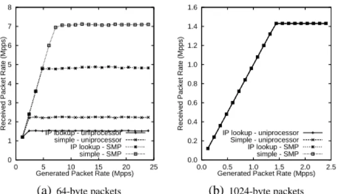
Figure 4: Effect of additional memory accesses on forwarding performance.
The HEN[8] testbed used for our experiments consists of a large number of PowerEdge systems connected together by a single non-blocking, constant-latency gigabit Ethernet switch. We used Linux 2.6.19.2 for the operating system and the Click modular router package (version 1.6 but with patches eliminating SMP-based locking issues) with a polling driver for the actual packet forwarding. Test traffic was gen-erated by similar machines, each underutilised so as to be able to generate or receive packets at line-rate for any packet size.
2.1
Basic forwarding numbers
To understand the baseline performance, we first exam-ine the forwarding limits of a single CPU core, where each packet is moved from an incoming interface to an outgo-ing one without any header or payload processoutgo-ing. Figure 2 shows how forwarding performance saturates as we increase the incoming packet rate. The curves on the graph represent increasing numbers of flows set-up between separate pairs of interfaces, up to the maximum of 6 that our machines can support when all twelve interfaces are being used.
Figure 2(a) shows that with 64-byte packets the router had already saturated at around 2.5Mpps, and adding extra flows did not help. With larger packets, the story is rather different. In this case, the curves level off not because of forwarding saturation, but because the incoming links are saturated. A single CPU core can forward all twelve gigabit flows at line rate without loss.
For a single CPU core then, the limitation appears to be processing power when the aggregate forwarding rate ex-ceeds 2.5Mpps. With 1024-byte packets this means that we would need about 20 gigabit interfaces in the machine in or-der to saturate this single core.
In 2008, the trend is for manufacturers to increase system performance by having mulitple CPU cores on each proces-sor die because single core systems are nearing the limits of their performance. For small-packet forwarding, the ob-vious question is whether we can effectively make use of more cores.
Figure 3(a) shows the effect of increasing the number of
unidirectional flows of 64-byte packets while using an addi-tional core for each addiaddi-tional flow. The performance scales perfectly with the number of cores for the first four giga-bit flows, indicating that forwarding had indeed been CPU-limited. However, we hit a hard limit around 7.1Mpps, and adding more flows and CPU cores does not increase this limit. Figure 3(b) shows very similar behavior for bidirec-tional flows, with linear scaling up to 7.1Mpps. This limi-tation cannot be due to lack of processing power, because it does not increase as we add extra cores. It also cannot be a hard bound on throughput (at least not in bytes per second) because 7.1Mpps corresponds to a bitrate of 3.64Gb/s and we have already seen that this hardware can forward 12Gb/s with larger packets. Where then, does the bottleneck lie?
One clue comes from Figure 4(a). In the previous exper-iments we were doing the most simple packet forwarding possible, without conducting an IP lookup or modifying the packet in any way. In Figure 4 we compare the performance of the simple forwarding with that of a full IP lookup and TTL modification, showing both the single-core case and the 6-core SMP case. In the case of 1024-byte packets, the extra work per packet does not cost us anything, and we can still forward at 12Gb/s. In the case of 64-byte packets, the ex-tra work decreases the forwarding performance by approxi-mately 30%. For the single processor case we might expect this, as the CPU is the bottleneck and now it has more work to do. However, in the 6-core case the aggregate rate of all six cores is only slightly more than three times the rate of a single core. If CPU cycles were the issue, we should be able to do better than this.
2.2
Life cycle of a packet
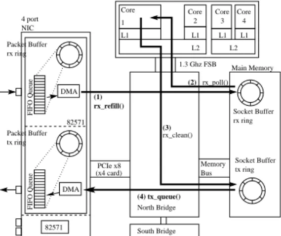
To understand how packets are forwarded from an inter-face to another, let us examine the path a packet takes through a software router from ingress to egress interface (Figure 5). At a basic level, a Click forwarding path can be con-sidered as a receive and a transmit path connected together by a queue.
• Packets from the NIC’s hardware queue are copied into
the main memory using DMA (arrow (1) in Figure 5). Typically a fairly long chain of DMA buffers is handed to the NIC, which it uses as packets arrive.
• When the relevant PollDevice element is scheduled by
the kernel, the rx ring is polled (arrow (2)). Packets there are processed by the Click inbound forwarding path and placed in Click’s internal queue (not shown). The transmission path also has two main parts:
• When Click’s transmit path is scheduled, it pulls
wait-ing packets from Click’s queue, performs outgowait-ing pro-cessing, and enqueues them in the DMA transmit ring (arrow (3)). The DMA buffer descriptor is written so that the DMA engine knows where to find the packet.
• Finally the NIC transfers the packet using DMA to its
own outgoing queue (arrow (4)).
Socket Buffer rx ring Socket Buffer tx ring DMA DMA 4 port NIC Packet Buffer tx ring Packet Buffer rx ring 82571 PCIe x8 (x4 card) 1.3 Ghz FSB L1 Core 2 Core 1 L1 L2 L2 Core L1 Core L1 3 4 rx_poll() (2) Memory Bus rx_clean() (3) rx_refill() (1) (4) tx_queue() North Bridge Main Memory South Bridge FIFO Queue FIFO Queue 82571
Figure 5: Path a packet takes as it is forwarded from an input to an output interface. The diagram assumes that
Click and the e1000 driver are used.
2.3
Identifying the limitation
The limitation of 7 Mpps (millions of packets per second) seems strange because the CPU, memory and buses all ap-pear to have headroom given the other experiments. To nar-row down the limitation, we first must examine where pack-ets are being dropped. NIC counters indicate that packpack-ets are being dropped from the NIC queue. There are really just two possibilities: either the CPU is not allocating DMA buffers to the NIC fast enough, or the NIC cannot use the buffers it has been allocated fast enough. When we go to poll a packet we added checks to see how many packets had been DMAed and were ready in main memory. The number turns out to be rarely more than one, and usually zero. If the NIC was running out of DMA buffers to use, then these buffers would hold received packets in memory. This is not the case, so the problem is clearly that the NIC is having difficulty DMAing packets to memory at a fast enough rate.
2.3.1
Could polling result in livelock?
One possible cause is that the CPUs are causing memory livelock by polling the packet descriptors in main memory at too high a rate, preventing the DMA controller accessing memory. However, when we use the CPU cycle counter to reduce the polling rate this has no effect on the forwarding rate. Thus it would seem that the CPU is neither causing memory livelock nor is short of resources to perform polling.
2.3.2
PCIe bus
Another possible bottleneck is the PCIe bus (this term is a misnomer, as PCIe is a switched interconnect). The PCIe bus of each network card has the ability to transfer 8Gb/s (4 x 250 MByte/s) in each direction, giving a bi-directional data rate of 16Gb/s. Clearly the limitation isn’t bandwidth, because with large packets we achieve line rate, giving a bi-directional forwarding rate of 8Gb/s. With small packets we hit the limit at only 7.5% of the available bus bandwidth. The problem cannot be a bus access latency issue (as was common on PCI-X) either, as the forwarding limit is not sig-nificantly changed if we concentrate four bidirectional flows on one pair of quad-cards, or spread them across all three cards.
It is important to note that according to the PCIe specifi-cation, at most 256 bytes can be carried within a PCIe trans-action, which means that upon forwarding minimum sized packets each DMA transaction involves only a single PCIe transaction.
2.3.3
Memory performance
The data rate of recent DRAM chips looks sufficient for high performance packet forwarding (e.g., the PC2-5300 mod-ules in our system have a data rate of 5312MB/s, while DDR3 memory modules can have bandwidths over 15GB/s). Un-fortunately, these bandwidths are only achievable when con-tiguous memory is read or written, and this is not the case when small packets are forwarded via main memory.
In section 2.2 we saw the main steps when packets are for-warded from ingress to egress, which helps understand the role of main memory. To extend this picture, we have to take into account the reads and writes of the packet descrip-tors, both by the NIC and by the CPU. It is hard to tell from reading the code exactly which accesses hit the CPU cache and which are forced to access the main memory. Hence, we measured the number of completed memory bus transac-tions using Oprofile [9]: Figure 6 shows the results per driver function. These results only reflect CPU memory accesses, omitting those initiated by the card. For each data transfer, the NIC needs to read a buffer descriptor indicating where in memory to obtain or place the packet, and it needs to update the descriptor after the transfer, so the CPU knows it is com-plete (thus adding three NIC generated memory accesses per data transfer). In total then, it requires about ten memory ac-cesses per packet forwarded. As socket buffers for different interfaces are allocated at separate memory locations,
con-0 1 2 3 4 5 1 2 3 4 5 6 7 8 9 10
Mem accesses per packet
Generated packet rate (Mpps) Total rx_refill rx_poll tx_clean tx_pqueue rc_checksum
Figure 6: Number of memory bus transactions per packet.
secutive DMA transactions are going to access the memory at discontiguous memory locations.
We are able to transfer 7.1Mpps, which translates into 140ns per packet. On average then, each memory access has 14ns to complete. The memory in our systems is DDR2-666, which has a clock speed of 333MHz or 3ns per bus clock cy-cle. Thus on average, a memory access needs to take place every 4.7 bus cycles.
TCL 5 CAS Latency
TRCD 5 RAS-to-CAS delay
TRP 5 RAS Precharge
TRAS 15 Active to Precharge delay
The table above shows the access latencies of the mem-ory modules in our machines. What is the effect of a con-stant sequence of 16 (size of the descriptors) and 60 (size of a minimum sized packet) bytes reads or writes to sepa-rate (i.e., discontiguous) locations? With DDR2 memory, addresses are asserted in two phases. First the Row Address Select (RAS) is applied, then the Column Address Select (CAS) is applied and finally data can be transferred, 16 bytes per half-clock cycle (and two clock cycles are needed per 60 bytes) for several clock cycles if desired. If memory access are consecutive, memory bandwidth is very high. For sub-sequent addresses, if the column address does not change, a new CAS value can be asserted, so accesses can be approx-imately 5 bus cycles apart. However if memory accesses are random and short, the overhead of precharge, RAS, and CAS can be paid, and writes must be 15 bus cycles apart. Thus there is a factor of 30 between the fastest consecutive accesses and the slowest non-consecutive accesses.
When we compare the average 4.7 cycles per memory ac-cess with these memory latency figures, the result is very close to the 5 cycle CAS latency, which is the lowest de-lay we might reasonably expect. Simply, memory latency seems to be the bottleneck for our routers. These figures are of course somewhat simplistic; it takes a few half-cycles to transfer the data at 16 bytes per half-cycle; writes are actu-ally cheaper than reads on DDR2; more than one buffer de-scriptor might be updated in one burst-write; some memory accesses will likely be on different rows, so pay the full RAS and CAS delay, and so on. But overall, the best we can ex-pect to get from our memory system is very similar to what we do in fact obtain. The evidence is clear - on a uniform
0 1 2 3 4 5 6 7 0 2 4 6 8 10 12
Received Packet Rate (Mpps)
Generated Packet Rate (Mpps) 6 bidirectional flows
(a)64-byte packets - unidirectional flows
1 2 3 4 5 6 7 0 5 10 15 20 25
Received Packet Rate (Mpps)
Generated Packet Rate (Mpps) 6 bidirectional flows
(b)64-byte packets - bidirectional flows
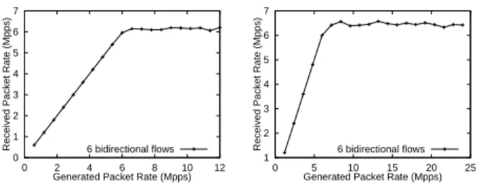
Figure 7:One and two-way forwarding performance for an AMD NUMA multi-processor router.
memory architecture such as provided by our Intel CPUs, memory latency is the limiting factor for small packets.
In our testbed network we also have a 4 node NUMA (Non-Uniform Memory Architecture) AMD x4500 server, in which each node consists of a dual-core Opteron 8222 CPU and 4GB memory. Figure 7 shows the maximum for-warding rate we measured on this NUMA system, which rate is obviously lower than the results of the server with uni-form memory architecture. The main reason for this is, that NUMA support for descriptor ring and socket buffer alloca-tion is missing both from Click and the used Linux kernel version (2.6.19.2), thus resulting in the usage of only one of the nodes memory and as a consequence in 75% remote (and expensive) memory accesses.
2.4
Core allocation
Given the memory bottleneck, it immediately becomes clear that CPU L2 cache performance is critical, as this re-duces the need to access main memory. When forward-ing packets we have to decide which cores do what part of the work. On our multi-core systems, some cores share L2 caches and some do not. This allows us to investigate how the CPU cache affects forwarding performance.
We constructed a Click configuration consisting of two forwarding paths, each performing standard IP forwarding in compliance with standards [10]. Two CPU cores were allocated, using the four mappings shown in Figures 8(a) to 8(d). Figure 8(e) shows the aggregate forwarding rate for each mapping and the theoretical limit (nearly 3Mpps for 64 byte packets).
With one core (Figure 8(a)) the achievable rate is about 1.6Mpps. Adding another core from a different CPU so that one core handles inbound packets and the other handles out-bound packets (Figure 8(b)) actually decreases performance. The reason for this is that packets switch CPUs. As they are not in the CPU cache of the second core, this requires extra memory accesses, adversely affecting performance.
Running the same experiment with two cores that do share an L2 cache (Figure 8(c)) improves performance over the single core case; this is further indication that memory ac-cesses are the bottleneck. However, to further improve the performance we allocated the cores so that each was only processing the packets of a single forwarding path (Figure 8(d)). This is an optimal setup as the packets stay in the L1
PD Q TD
PD Q TD
CPU 1
(a)One Core
PD Q TD
PD Q TD
CPU 1 CPU 5
(b)Two Cores, Diff. L2
PD Q TD
PD Q TD
CPU 1 CPU 2
(c)Two Cores, Same L2
PD Q TD
PD Q TD
CPU 1
CPU 2
(d)Two Cores, One per path
0.5 1.0 1.5 2.0 2.5 3.0 0.5 1.0 1.5 2.0 2.5 3.0 3.5 4.0
Received Packet Rate (Mpps)
Generated Packet Rate (Mpps) Theoritical maximum
1 core (a) 2 core (b) 2 core - L2 cache shared (c) 2 core - 1 per FP (d)
(e)Forwarding rate of each configuration
Figure 8: Click configuration for naive thread assignment
cache of each core.
2.5
Complex Flow Patterns
So far we have concentrated on teasing apart the factors that limit forwarding performance; primarily these are CPU cycles on a single-core machine and memory accesses when multiple cores are used. However, the job of a real router is more complex than our experiments so far. In particular, there is no nice pairing of incoming and outgoing interfaces. The merging of packet flows further reduces performance because this brings additional limitations into play. Before we examine the options for virtualising routers, it is impor-tant to understand these limitations.
As we have shown above, a reasonable starting point for core-to-interface mapping is to allocate incoming interfaces to cores, and dynamically map outgoing interfaces to these same cores according to traffic flows so that the largest num-ber of packets do not have to switch cores. However, if we do this, some packets will nonetheless need to switch cores. Consider the two scenarios shown in Figure 9. In the first, some flows must switch cores. In the second, some flows converge on an outgoing interface. How do this more com-plex flow patterns affect performance?
Consider first the scenario from Figure 9(a). The left curves in Figure 10 show the performance of flows 0 and 1 when the cores share an L2 cache and when they do not. Again the limiting factor of memory accesses is clear, with the L2 cache improving performance significantly.
PD_0 Q TD_0 PD_1 Q TD_1 CORE 1 CORE 2 Flow 0 Flow 0 Flow 1 Flow 1
(a)Two flows each crossing CPUs
PD_0 Q TD_0 PD_1 CORE 1 CORE 2 Flow 1 Flow 1 Flow 0 Flow 0 (b)Meeting flows
Figure 9:Packet flows relative to interfaces and CPUs
0.0 0.2 0.4 0.6 0.8 1.0 1.2 1.4 1.6 0.0 0.5 1.0 1.5
Received Packet Rate (Mpps)
Generated Packet Rate (Mpps) Flow 0: different CPUs) Flow 1: (different CPUs) Flow 0: (shared L2 cache) Flow 1: (shared L2 cache)
0.0 0.5 1.0 1.5 2.0
Generated Packet Rate (Mpps) Flow 0: (different CPUs) Flow 1: (different CPUs) Flow 0: (shared L2 cache) Flow 1: (shared L2 cache)
Figure 10: Performance of the scenario in Figure 9(a). Left: two cores are used; packets switch cores at the queue. Right: four cores are used, so
inbound and outbound traffic is handled by different cores.
This is, however, not the whole story. The right curves in Figure 10 show a very similar scenario, but four cores are used instead – one for each inbound branch and one for each outbound branch. The number of memory accesses should be the same as before, but the curves show noticeably better performance. If memory were the only limiting factor, the two sides would be the same.
The cause is the Click scheduler. Inbound and outbound branches are tasks; on each core tasks are scheduled in a round-robin manner, and are not pre-empted. It turns out that tasks can interfere with each other. When the inbound branch has the CPU and in turn is spending most of its time waiting on memory, the outbound branch cannot be sched-uled, and vice versa. The effect is that we miss opportunities to transmit packets, lowering performance.
The scenario from Figure 9(b) is somewhat worse. Fig-ure 11 shows the results of the scenario where the two cores do not share L2 caches, but they enqueue their packets into a single internal Click queue. Figure 11 shows how two equal-rate flows share the outgoing link. Up until the out-going link saturates, their share is equal. However, after the link saturates, the share becomes increasingly unfair. The Click queue starts to fill up, so some packets that are re-ceived are not forwarded, resulting, on one hand, in wasted work, while on the other, in unfair loading of the internal queue. Essentially two cores are competing to put packets into a single queue, but one of these cores must also handle the dequeuing and transmitting the packets of this queue. It is unsurprising that the less loaded core (the one that is able to push its packets into the queue uninterruptibly) wins this battle, giving the unfair results shown. To resolve the
prob-0.0 0.2 0.4 0.6 0.8 1.0 0.0 0.5 1.0 1.5 2.0 Received Rate (Mpps)
Generated Packet Rate (Mpps) Flow 0 : PD_0 -> TD_0 Flow 1 : PD_1 -> TD_0
Figure 11: Packet forwarding rate of the scenario in Figure 9(b)
lem of the fairness issue caused by the shared Click queue, a separate internal queue is needed for every input element (i.e. PollDevice) and a fair scheduling multiplexer needs to be placed between these queues and the output element (i.e. ToDevice).
Once traffic flows become more complex, the behavior of the scheduler becomes very important on multi-core sys-tems. In particular, if a Click queue is overflowing, a good scheduler strategy would be to reduce the polling rate of in-coming interfaces feeding that queue. However, this is only possible if the incoming interface is not also feeding inter-faces that are lightly loaded, or these other flows will also be throttled. The alternative is to implement fair queuing be-tween packets from different incoming interfaces. This will achieve better fairness, but at the expense of wasting mem-ory accesses on packets that will eventually be dropped at the queue, unless of course virtual queueing is supported in hardware on the NIC (see Section 3.2).
3.
EXPLORING ROUTER VIRTUALIZATION
When virtualising routers we have the option of perform-ing the virtualisation of the forwardperform-ing plane ourselves in Click, using an off-the-shelf virtualisation solution, or using a hybrid of the two. Clearly OS-level virtualisation provides effective isolation, but the question is whether the isolation comes at the cost of performance. Two significantly dif-ferent virtualisation solutions are Xen [1], which provides hardware-level virtualisation and OpenVZ [11], which pro-vides OS-level virtualisation. We were interested in seeing how their design choices affect virtual router performance and flexibility.
In OpenVZ a kernel is virtualised into so-called “contain-ers” by replicating the kernel data structures and multiplex-ing system calls from each container into the underlymultiplex-ing op-erating system kernel. Note that in such a system, there is only a unique kernel that supports and implements the con-tainers, so the containers can be considered “clones” of this kernel. This approach results in low virtualisation overhead. Xen in contrast uses hardware virtualisation to share re-sources between different guest domains. A hypervisor or virtual machine monitor (VMM) schedules access to the CPUs of the host system and is controlled by a special guest do-main, dom0, which is booted along with the hypervisor. Xen guest domains can run different operating systems
concur-Hypervisor NIC NIC NIC NIC FP2 FP1 Click (kernel) Dom0
(a) Common Forwarding Plane
NIC NIC Click (kernel) FP1 NIC NIC Dom0 Hypervisor DomU Click (kernel) FP2
(b) Interface Direct Mapping
NIC
NIC NIC NIC
VNIC FP1 VNIC FP2
Click (kernel) Dom0
Hypervisor
FP3 DomU
Click (kernel)
(c) Hybrid Forwarding Plane
Figure 12: Xen Configurations
rently.
3.1
System Virtualisation
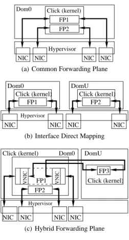
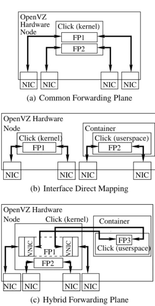
It is possible to compose a virtual software router in three different configurations where packet forwarding is under taken by using one of the following schemes.
• Common forwarding plane : All virtual forwarding
paths are in a common forwarding domain (Figures 12(a) and 13(a)).
• Interface direct mapping : Each virtual forwarding path
is in its own guest domain with interfaces directly as-signed to it (Figures 12(b) and 13(b)).
• Hybrid forwarding plane : Traffic for a virtual
forward-ing path is filtered from a shared forwardforward-ing domain into a guest domain (Figures 12(c) and 13(c)). The first configuration, shown in Figures 12(a) and 13(a), has a common forwarding domain for all virtual software routers on the box. This is probably best suited to situa-tions where all the forwarding paths are composed of stan-dard Click elements, where there is no need to isolate custom forwarding paths in separate domains for reasons of security. Using a common forwarding domain for a number of differ-ent virtual routers is very efficidiffer-ent and allows a large number
NIC NIC NIC NIC FP2 FP1 Click (kernel) Node Hardware OpenVZ
(a) Common Forwarding Plane
NIC NIC Click (kernel) FP1 OpenVZ Hardware Node NIC NIC FP2 Container Click (userspace)
(b) Interface Direct Mapping
Node
OpenVZ Hardware
NIC
NIC NIC NIC
VNIC FP1 VNIC FP2 FP3 Container Click (userspace) Click (kernel)
(c) Hybrid Forwarding Plane
Figure 13: OpenVZ Configurations
of virtual routers to share the same interfaces. In Section 3.2 we explore the issues of virtual router scaling further.
The second configuration, Figures 12(b) and 13(b), di-rectly maps interfaces into guest domains enabling forward-ing planes to safely run untrusted forwardforward-ing paths.
The third possible configuration, Figures 12(c) and 13(c), is where a proportion of the packets from a set of interfaces is filtered in to a guest domain for further processing. This may be the most flexible configuration but current stability issues with the interaction between Click and the virtualiza-tion soluvirtualiza-tions preclude this being evaluated. We can evaluate native bridging and forwarding in this scenario, and will do so in Section 3.3.
To compare the performance of OpenVZ and Xen we take the first two schemes and evaluate their performance by re-peating the earlier multiprocessor experiment from section 2.1 with six bidirectional flows of 64 byte packets.
The left hand graph in Figure 14 compares the basic OpenVZ and Xen systems with simple forwarding using Click, stan-dard Linux forwarding is also shown to act as a baseline. For forwarding rates less than 6Mpps where the system is un-derloaded the two virtualization systems are only limited by rate of arriving packets. As the system becomes overloaded, OpenVZ’s light weight architecture comes into its own and
performs marginally better than Xen.
The right hand graph in Figure 14 shows the results of for-warding in three guest domains each of which has two pairs of interfaces directly mapped to each domain. For the Xen experiments each domain was allocated two cores, with one being allocated to each pair of interfaces. For the OpenVZ experiments each domain had access to all cores and it was left to the operating system to allocate them. Because Xen provides hardware virtualization Click is able to run in the kernel of each guest domain. OpenVZ’s operating system virtualization limits Click to running in userspace. The in-ability to run Click in the kernel space for each OpenVZ container severely curtails OpenVZ’s performance in com-parison to Xen. For Click to run efficiently in OpenVZ it would need to modified to support containerization.
If we require flexibility over the OS and the kernel that is run by each virtual router then Xen is a better choice than OpenVZ because it is not feasible to have a OpenVZ concur-rently run Linux, FreeBSD and JunOS. But OpenVZ offers marginal performance benefits over Xen because of its light weight architecture.
We have seen that for the common forwarding plane run-ning in the OpenVZ hardware node or Xen dom0, then OpenVZ performs best. However if you are willing to sacrifice a small amount of performance and use Xen then you gain the abil-ity to run other scenarios on the same system. If you want a flexible virtual software router then OpenVZ’s single ker-nel model is a significant disadvantage for virtual software routers where each virtual software router could be required to run distinct operating systems and kernels. When this is coupled with its current performance running Click, it clear that Xen is a better fit for a flexible software virtual routers than OpenVZ.
This might not be the fairest comparison. However, it is the best we can do given that the kernel version of Click lacks support for containerisation.
3.2
Interface Virtualisation
If a virtual router platform had to map each network inter-face into a single virtual router, this would severely impact
0.0 1.0 2.0 3.0 4.0 5.0 6.0 7.0 8.0 1.0 2.0 3.0 4.0 5.0 6.0 7.0 8.0
Received Packet Rate (Mpps)
Generated Packet Rate (Mpps) OpenVZ Host Native linux.
Xen Dom0 Native linux. OpenVZ Host Click Xen Dom0 Click
1.0 2.0 3.0 4.0 5.0 6.0 7.0 8.0 9.0
Generated Packet Rate (Mpps) OpenVZ
Xen
Figure 14: Performance of the different VMs with a consolidated forwarding domain (left) and directly mapped interfaces (right).
PollDev R ToDev R C L PP PP CL: Classifier PP: Packet Processing RR: Round-Robin Scheduler
(a)Software de-multiplexing
PollDev CL RR ToDev
PP PP
UNQ UNQ
(b)Software de-multiplexing with multi-queuing
PollDev ToDev PP PP PollDev ToDev
(c) Hardware de-multiplexing in a multi-queue NIC
Figure 15: Options for sharing interfaces between virtual routers
0 1 2 3 4 5 6 10 100 1000 Aggregate forwarding rate (Mpps)
Number of IP compliant routers Figure 16: Forwarding rate as we add virtual routers.
the flexibility provided by virtualisation and rule out a wide range of possible deployment scenarios. Thus a critical is-sue for a virtual router platform is how to share interfaces between virtualised routers. Mechanistically, the issue is straightforward; the different virtual links need some form of de-multiplexing tag, whether it be an Ethernet MAC address, VLAN tag, MPLS label or IP tunnel address. The more in-teresting question concerns the effect of interface sharing on overall performance and on fairness.
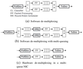
If an interface needs to be shared between virtualised routers, there are three main options for doing so:
• Use software to demultiplex the flows and process the
packets as they arrive, as shown in Figure 15(a).
• Use software to demultiplex the flows, but then
re-queue them on a per virtual router basis (Figure 15(b)). This allows fairer scheduling between virtual routers.
• Use hardware de-multiplexing in the NIC, and present
multiple hardware queues to the OS (Figure 15(c)). Simple software de-multiplexing has the great advantage of simplicity, and when all the forwarding planes are im-plemented in the same OS domain, this scales to very large
0.0 0.1 0.2 0.3 0.4 0.5 0.6 0.7 0.8 0.0 0.2 0.4 0.6 0.8 1.0 1.2 1.4
Received Packet Rate (Mpps)
Aggregate Generation Rate (Mpps) Low(33%) priority FP High(67%) priority FP
0.2 0.4 0.6 0.8 1.0 1.2 1.4
Aggregate Generation Rate (Mpps)
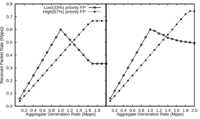
Figure 17: Per-flow forwarding rate with virtual routers prioritized 2:1 and software de-multiplexing. Traffic flow is 60% low priority traffic.
Left: synthetic ideal case, Right: actual case.
numbers of virtual routers, as shown in Figure 16. Only when the CPU caches start to thrash does performance dip.
The downside of simple software de-multiplexing is fair-ness. Packets are processed as far as the central queue in the order in which they arrive on the incoming interface, irre-spective of the intended prioritization of the virtual routers. Figure 17 illustrates the consequences of this. In this case there are two virtual routers, each receiving packets from a single shared interface and forwarding them out of a sec-ond shared interface. The routers are prioritised so that one router should achieve twice the throughput of the other, but 60% of the traffic arriving is for the lower priority router. Running on a single core to demonstrate the issue, this soft-ware de-multiplexed setup saturates at about 1Mpps. The ideal case is shown on the left - after saturation, the higher priority router should still be able to forward all the packets that arrive for it, at the expense of the low priority router. In fact, the situation on the right occurs because the packet ar-rivals dictate the scheduling options, and low priority pack-ets that are polled are still processed.
A partial solution might be to re-queue the packets after they are classified, and then apply a weighted fair-sharing algorithm to the elements dequeuing the packets from these additional queues as illustrated on Figure 15(b). However, apart from increasing the complexity, this would also re-sult in “excess” packets being discarded: a rather expensive after-the-fact strategy, as these packets have already used valuable memory accesses. In other words, not forwarding some of these low priority packets would not greatly increase the resources available for other forwarding engines to use.
This clearly indicates that if fairness and isolation are re-quired amongst shared forwarding engines, hardware packet classification is needed on the NIC (Figure 15(c)). Fortu-nately the rise of server virtualisation has created a mar-ket for just such hardware. Intel’s VMDq [12] enables the NIC to filter packets into different queues which can then be polled by different virtual routers. The number of filtered queues is hardware dependent but is limited to 16 for the Intel 82598, which slightly limits the scalability of this
ap-0.0 0.1 0.2 0.3 0.4 0.5 0.6 0.7 0.8 0.2 0.4 0.6 0.8 1.0 1.2 1.4 1.6 1.8
Received Packet Rate (Mpps))
Aggregate Generation Rate (Mpps) Low(33%) priority FP High(67%) priority FP
0.2 0.4 0.6 0.8 1.0 1.2 1.4 1.6 1.8 2.0 Aggregate Generation Rate (Mpps)
Figure 18: Per-flow forwarding rate with virtual routers prioritized 2:1 and hardware de-multiplexing. Traffic flow is 60% low priority traffic.
Left: synthetic ideal case, Right: actual case.
proach. A default queue is reserved for all the broadcast and multicast traffic whilst the others are classified based upon MAC addresses.
Figure 18 illustrates the benefits of a multi-queue approach. As we do not currently have a polling driver for VMDq NICs, we emulated the approach using two single-queue NICs and used the upstream Ethernet switch to classify the pack-ets and direct them to the correct NICs. So long as neither flow exceeds 1Gb/s, this will effectively emulate a 2Gb/s interface running VMDq. As before, 60% of the traffic is destined for the low-priority forwarding plane, whereas the Click scheduler aims to bias forwarding 2:1 in favor of the high-priority forwarding plane. In contrast to the software de-multiplexing approach, using hardware multiplexing al-lows the scheduler to function properly. Once the CPU core reaches saturation, packets from the high-priority router are not dropped until the high-priority traffic approaches its fair share of the processing resources. The synthetic ideal curve based on an assumed saturation point at 1Mpps is shown on the left, and the achieved results on the right. The fairness is not perfect, in part because the saturation point turns out to depend on the traffic distribution, but it is close enough for most purposes.
3.3
Virtual forwarding scenarios
So far we have discussed different system virtualisation technologies, leaning towards XEN as a more flexible plat-form for virtual software routers; we further illustrated the issues regarding virtualisation of network interfaces. In this section of the paper we bring these together, presenting dif-ferent XEN forwarding scenarios and discussing their suit-ability with regards to a virtual router platform.
3.3.1
Forwarding using I/O channels
Perhaps the most obvious scenario is the one depicted in Figure 12(c), where packets are received by dom0 and then sent to the domUs which contain the forwarding planes. This approach has its advantages: because dom02 classifies the
2A dom0 is a Xen master domain that has priviliged access to the
packets, the interfaces are essentially virtualised, and run-ning each forwarding plane on a separate domU3 provides isolation between the virtual routers. One downside to the scenario is that it is hard to provide fairness, since dom0 has to receive all packets first before classifying them into the domUs. 0 0.1 0.2 0.3 0.4 0.5 0.6 0.7 0.8 0 1 2 3 4 5 6 7 8 9
Received Packet Rate (Mpps)
Generated Packet Rate (Mpps) Linux native forwarding in dom0
Click forwarding in the domUs
Figure 19: Performance limitation of XEN’s I/O channel (64-byte packets). The biggest problem with this approach, however, is its performance. As shown in Figure 19, this setup only man-ages to forward 0.05 Mpps 64-byte packets per second when using 8 cores (one per domU); indeed, even native Linux in dom0 without polling (which does not take full advantage of the 8 cores when forwarding) can forward at close to 0.8 Mpps. The reason for such poor performance is that in order to transfer packets between dom0 and a domU, XEN uses I/O channels, requiring costly hypervisor domain switches. Previous research confirms this, showing that 30-40% of the execution time for a network transmit or receive operation is spent in the Xen hypervisor domain [13]. Recent work [14] has addressed this issue, but a currently a public implemen-tation is unavailable for testing.
3.3.2
Forwarding in dom0
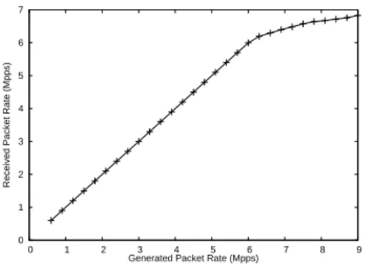
An alternative scenario is that shown in Figure 12(a), with dom0 handling all of the forwarding planes and using the domUs for the control planes. This scheme is also able to virtualise the network interfaces and even improves upon the previous one, since packets are not sent to the domUs which avoids the I/O channel bottleneck. In order to test the perfor-mance of this scenario, we used six uni-directional flows of 64-byte packets. As shown in Figure 20, removing the I/O bottleneck results in a significant increase in performance, forwarding close to 7 Mpps.
Unfortunately, this increase comes at a cost. Forward-ing everythForward-ing in dom0 means that the different forwardForward-ing planes are not isolated from each other, an important factor for a virtual router platform. Clearly this scenario provides a crucial improvement in performance with regards to the previous approach, but it is not without problems.
system.
3A domU is a Xen guest domain that has limited access to the sys-tem.
0 1 2 3 4 5 6 7 0 1 2 3 4 5 6 7 8 9
Received Packet Rate (Mpps)
Generated Packet Rate (Mpps)
Figure 20: Dom0’s forwarding performance for minimum-sized packets.
3.3.3
Forwarding using direct NIC mapping
In last scenario (see Figure 12(b)), network interfaces are directly mapped to domUs so that packets are directly trans-ferred to each domU’s memory via DMA. In terms of perfor-mance, using six forwarding paths, six domUs, six cores and six pairs of interfaces results in a forwarding rate of about 7 Mpps, just like in the previous scenario.
Beyond this, we want to consider the case where several domUs share a core, which could arise if the number of vir-tual routers were high. To test this, we first assigned 2 do-mUs and then 3 dodo-mUs to a single core, and compared these to the performance in the previous scenario, where all for-warding planes are in dom0. The results (shown in Figure 21) show that sharing a core among an increasing number of domUs yields a decrease in forwarding performance;
0 0.2 0.4 0.6 0.8 1 1.2 1.4 1.6 1.8 2 0.5 1 1.5 2 2.5 3
Received Packet Rate (Mpps)
Generated Packet Rate (Mpps) 3 domUs with NICS directly mapped 2 domUs, with NICS directly mapped 3 flows in dom0 2 flows in dom0
Figure 21: Direct mapped domains sharing a single core In the end, we believe that this decrease in performance will not be an issue in the future, since CPUs with 32 cores are already available, and Intel engineers are already talk-ing about chips with core counts in the hundreds and even thousands. Another potential problem with this approach is that each domain needs its own interfaces, and it would seem that, at first sight, the number of forwarding domains would be limited by the number of physical interfaces on the sys-tem. As it turns out, this will no longer be an issue in the near future, since hardware virtual queuing is already supported at least in Intel’s 10Gb cards (although work is needed so that the Linux driver for this card will work with Click). The fact that current hardware trends eliminate this scenario’s
biggest performance bottlenecks, coupled with the fact that it provides excellent isolation and fairness among forward-ing planes leads us to believe that commodity hardware is a viable platform for constructing high performance virtual routers.
4.
CONCLUSION
Contrary to conventional wisdom, we have shown that the forwarding performance of modern software routers is actu-ally rather good. An inexpensive modern x86 rack-mount server can forward minimum-sized packets at several giga-bits per second and larger packets at much higher rates.
However, getting this sort of performance is not trivial, and naive approaches will result in an order of magnitude less throughput. The fundamental limit on forwarding per-formance is currently memory latency. Although these sys-tems have huge memory bandwidth, they frequently cannot make use of this due to poor locality of reference in the DMA controller hardware and PCIe arbitration. It is clear that smarter hardware could make much better use of mem-ory bandwidth. Bursting transfers of several back-to-back packets from one NIC at a time into contiguous memory regions might increase throughput significantly. As more and more cores become available, it may become feasible to turn off DMA and to dedicate cores to the role of trans-ferring data between the NICs and memory in the best way to maintain memory throughput. This essentially gives us a programmable DMA controller.
NUMA architectures, which effectively provide “concur-rent, full-speed” memory access by giving each CPU its own memory controller and associated bank, should somewhat improve this situation and may shift the bottleneck onto an-other sub-system, as long as various packets and associated descriptors can be kept in the appropriate physical memory locations to exploit concurrent memory access to the full. While NUMA potentially offers a way to break the current performance wall, note that the gain would scale in terms of numbers of CPU, not numbers of cores. Coupled with the promise of ever increasing numbers of cores per CPU chip, our findings suggest that computing power will stay in vast surplus in software router systems.
The allocation of tasks to cores is also critical for per-formance. The goal is clear: operations touching the same packet must do so within the same cache hierarchy to avoid expensive main memory accesses. If this is done, then com-plex router applications (e.g., intrusion detection, deep packet inspection, etc) are well within the reach of modern com-modity hardware.
The spare computing capacity available facilitates the pro-vision of high-performance virtual router platforms. Our ex-perimentation with current system virtualisation approaches shows that the performance of virtual routers is extremely sensitive to various system issues. Our conclusion is that currently the best performance is achieved by virtualising forwarding engines within a single forwarder domain.
Do-ing so yields aggregate performance close to that realised without virtualisation, proving that software virtual routers do not have to exhibit low performance. We also show else-where [15] how isolation and fairness can be reconciled with performance in such an approach. However, I/O performance for guest domains is receiving research attention [14], so in the future, a forwarder domain may no longer be neces-sary. Direct mapping of properly abstracted hardware virtual queues could also provide a suitable alternative solution.
In line with our work, but in the context of distributed software routers, [16] also identifies memory as the main system bottleneck on modern commodity hardware. The au-thors reach this conclusion using proprietory Intel diagnosis tools, but differ somewhat from us when explaining the rea-sons behind the bottleneck.
A different approach is presented in [17], which proposed hardware assisted router virtualisation, with an explicit de-coupling between the control planes running on commod-ity hardware, and the forwarding plane running on network processors. Our focus is on using commodity hardware for forwarding because it offers better flexibility and ease of de-ployment. While we have mainly focused on forwarding performance, virtual control planes can easily be supported as separate guest domains in our approach. However, should this prove a performance limitation, an explicit separation of slow and fast planes is also possible in an all PC set-up.
So far we have only considered a virtual router platform built using a single virtualisation system. One possible hy-brid solution would be to use Xen for the forwarding plane and OpenVZ for the control plane, which is possible by tak-ing advantage of hardware virtualisation to prevent the two clashing. Besides letting us run non-Linux OSes, Xen has the advantage of allowing us to use Click for the forwarding plane without modifications. OpenVZ’s architecture, on the other hand, naturally lends itself to running multiple control planes concurrently because it only runs a single instance of the kernel, enabling the guest control planes to be hidden from one another without requiring software modifcations to the control software.
Overall, our findings indicate that although router virtual-isation is still at an early stage of research, solutions based on current and near-future commodity hardware represent a flexible, practical and inexpensive proposition.
5.
REFERENCES
[1] P. Barham, B. Dragovic, K. Fraser, S. Hand, T. Harris, A. Ho, R.Neugebauer, I.Pratt, and A. Warfield, “Xen and the art of virtualization,” in 19th ACM Symposium
on Operating Systems Principles. ACM Press,
October 2003.
[2] “Introducing vmware virtual platform, technical white paper,” 1999.
[3] “Intel vanderpool technology for ia-32 processors (vt-x) preliminary specification,” 2005.
[4] R. J. Creasy, “The origin of the vm/370 time-sharing
system.” IBM Journal of Research and De-velopment, vol. 25, no. 5, p. 483490, September 1981.
[5] A. Bavier, N. Feamster, M. Huang, L. Peterson, and J. Rexford, “In vini veritas: realistic and controlled network experimentation,” SIGCOMM Comput.
Commun. Rev., vol. 36, no. 4, pp. 3–14, 2006.
[6] N. Egi, A. Greenhalgh, M. Handley, M. Hoerdt, L. Mathy, and T. Schooley, “Evaluating xen for virtual routers,” in PMECT07, August 2007.
[7] S. Bhatia, M. Motiwala, W. Muhlbauer, V. Valancius, A. Bavier, N. Feamster, L. Peterson, and J. Rexford, “Hosting virtual networks on commodity hardware,” Georgia Tech. University., Tech. Rep. GT-CS-07-10, January 2008.
[8] “Heterogeneous experimental network,” http://www.cs.ucl.ac.uk/research/hen/. [9] J. Levon and P. E. et al., “Oprofile,”
http://oprofile.sourceforge.net.
[10] F. Baker, “Requirements for IP Version 4 routers,”
Request for Comments 1812, June 1995,
http://ftp.ietf.org/rfc/rfc1812.txt. [11] OpenVZ Project, “OpenVZ Project,”
http://www.openvz.org.
[12] R. Hiremane, “Intel virtualization technology for directed i/o (intel vt-d),” Technology@Intel Magazine, vol. 4, no. 10, May 2007.
[13] A. Menon, J. R. Santos, Y. Turner, G. J. Janakiraman, and W. Zwaenepoel, “Diagnosing performance overheads in the xen virtual machine environment,” in
Proceeding of the first International Conference on Virtual Execution Environments, Chicago, Illinois,
USA, June 2005.
[14] J. R. Santos, Y. Turner, J. Janakiraman, and I. Pratt, “Bridging the gap between software and hardware techniques for i/o virtualization,” in Proceedings of the
USENIX’08 Annual Technical Conference, Boston,
Massachusset, USA, June 2008.
[15] N. Egi, A. Greenhalgh, M. Handley, M. Hoerdt, F. Huici, and L. Mathy, “Fairness issues in software virtual routers,” in Proceedings of PRESTO’08, Seattle, USA, August 2008.
[16] K. Argyraki, S. A. Baset, B.-G. Chun, K. Fall, G. Iannaccone, A. Knies, E. K. U. M. Manesh, S. Nedveschi, and S. Ratnasamy, “Can software routers scale?” in Proceedings of PRESTO’08, Seattle, USA, August 2008.
[17] J. Turner, P. Crowley, J. DeHart, A. Freestone, B. Heller, F. Kuhns, S. Kumar, J. Lockwood, J. Lu, M. Wilson, C. Wiseman, and D. Zar, “Supercharging planetlab - a high performance, multi-application, overlay network platform,” in Proceedings of