HAL Id: hal-02306783
https://hal-ensta-bretagne.archives-ouvertes.fr/hal-02306783
Submitted on 7 Oct 2019
HAL is a multi-disciplinary open access
archive for the deposit and dissemination of
sci-entific research documents, whether they are
pub-lished or not. The documents may come from
teaching and research institutions in France or
abroad, or from public or private research centers.
L’archive ouverte pluridisciplinaire HAL, est
destinée au dépôt et à la diffusion de documents
scientifiques de niveau recherche, publiés ou non,
émanant des établissements d’enseignement et de
recherche français ou étrangers, des laboratoires
publics ou privés.
A Low-Cost Test Bench for Underwater Thruster
Identification
Abdelmalek Laidani, Mohamed Bouhamida, Mustapha Benghanem, Karl
Sammut, Benoit Clement
To cite this version:
Abdelmalek Laidani, Mohamed Bouhamida, Mustapha Benghanem, Karl Sammut, Benoit Clement.
A Low-Cost Test Bench for Underwater Thruster Identification. Conference on Control Applications
in Marine Systems, Robotics, and Vehicles, Sep 2019, Daejeon, South Korea. �hal-02306783�
A Low-Cost Test Bench for Underwater
Thruster Identification
Abdelmalek LAIDANI∗,∗∗Mohamed BOUHAMIDA∗ Mustapha BENGHANEM∗ Karl SAMMUT∗∗∗
Benoit CLEMENT∗∗,∗∗∗
∗AVCIS Research Laboratory, Department of Automatics, USTO-MB,
Oran, Algeria, (e-mail: [email protected]).
∗∗Lab-STICC, UMRCNRS 6285, ENSTA-Bretagne, 29806 Brest
Cedex 9, France (e-mail: [email protected]).
∗∗∗Flinders University, Adelaide, SA 5042, Australia (e-mail:
Abstract: Underwater vehicles are increasingly being used for the inspection of marine struc-tures, bathymetry and underwater intervention applications. The manoeuvring performance of these vehicles is critically dependant on the quality of the thruster model which must faithfully represent the relationship between the thruster inputs and corresponding outputs. Thruster manufacturers typically provide only the essential electrical, mechanical and thrust performance characteristics, for this reason the identification of the thruster’s parameters is especially important for constructing a reliable control system for the underwater vehicle. Physical testing using some form of test bench is normally used for identifying the thruster parameters. These test benches usually consist of a water tank and the thruster which is clamped to some form of instrumented reaction frame for measuring the model parameters. The cost of a test bench varies according to two major factors which are the size and the instrumentation which strongly depends on the physical quantities that we are trying to measure. In this article we will make a state of the art survey of existing test benches in order to provide a technical basis that will allow us to build a low-cost test bench. A thruster will be modelled using the resulting test bench and the outcomes will be presented at the end of this paper.
Keywords: System Identification, Test Bench, Thruster Model. 1. INTRODUCTION
A thruster is an fundamental element in an autonomous underwater or remotely operated vehicle (AUV/ROV), it consists of a motor and a propeller to generate a thrust that can move the vehicle (Aras et al. (2013a)). Given that the thruster is located within the innermost control loop of the vehicle control system, then it is essential in to order to achieve good manoeuvring control that the thruster model accurately represents the thruster characteristics. The subject of thruster modelling and control are still the object of various research studies published in the literature (Muljowidodo et al. (2009); Yang et al. (2015)). The composition of an underwater thruster is generally based on an electrical motor and the thrust force depends on the model of the motor, the propeller and other factors that make obtaining the mathematical model more complex.
To obtain a model of a thruster without going through a complex mathematical development, it is necessary to use identification to construct the model from measured input-output data that is obtained from a test bench. A test bench for the identification of underwater thrusters is generally constituted by (Guibert (2005)): a test tank filled with water, the system of propulsion (motor + propeller) and instrumentation which will make it possible to control
the thruster and the measurement of the different physical quantities needed. The size of the test bench will depend on the size of the thruster being identified, its realization is multidisciplinary because it requires skills in electrical and mechanical engineering. A literature study made by Guib-ert (2005), shows that several laboratories have developed various test benches in order to model thrusters.
The organization of this article will be as follows: a state of the art review of the literature on the test benches already realized will be introduced in Section 2 while mentioning the advantages and disadvantages of each of them. In Section 3 we will make a comparison between the test benches based on the measurement sensors and the mechanical reaction frame. The description of the realized test bench will be discussed in Section 4 by detailing the mechanical part (tank, mechanical reaction frame and thruster) and electronic part (sensors and data acquisition system). In Section 5 we present the results obtained and we make a comparison with a commercial thruster. In the final section the conclusions and perspectives will be presented and discussed.
2. STATE OF ART ON THE TEST BENCHES The first underwater thruster test bench realized by Dy-namical System and Control Laboratory (DSCL) is
de-scribed in Whitcom and Yoerger (1999), it consists of a cylinder tank with a depth of 3.5 m and a diameter of 5 m, a support structure composed of a fixed horizontal beam that overhangs the tank and a vertical beam with pivot connection that keeps the thruster in the tank. A force sensor is located in the other non-submerged end of the pivoting beam at the same distance as the thruster, therefore the sensor directly returns thrust measurements generated by the thruster. The following Fig. 1 shows the test bench:
Fig. 1. DSCL test bench
This test bench was made to test a thruster of 1 kWatts with a voltage of 120 Volts. This thruster is based on a brushless electrical motor and a propeller of 246 mm diameter. In the instrumentation part, a force sensor ranging from -960 to +960 Newton was used as well as an encoder with a resolution of 4096 Pulses/Revolution. This first test bench of DSCL could measure the force generated by the thruster in one direction only, to measure the force in the other direction it was necessary to reverse the disposition of the thruster. A second test bench was made to correct the deficiencies of the first (Bachmayer et al. (1999)). This test bench is composed of a vertical beam fixed by four brackets. A 6-axis force sensor is inserted between the thruster and the vertical beam (Fig. 2). This test stand is designed to support and test a wide variety of thrusters.
At Florida Atlantic University’s Department of Ocean Engineering (DOE) (Guibert (2005)), tests on the SQUID Autonomous Uunderwater Vehicule (AUV) were con-ducted in a 26,500 liters test tank with a section of 1,7 m2 using an elastic element equipped with a strain gauge to measure the thrust produced (Fig. 3).
Fig. 4 shows the test bench of the Centre of AUV Research (CAUVR) as used in Healey et al. (1995) and Cody (2003) to measure the thrust of a thruster to obtain its model.
Fig. 2. Second test bench of DSCL
Fig. 3. Test bench of DOE: testing SQUID AUV
Fig. 4. Test bench of CAUVR
Fig. 5. Test bench of DSL
Fig. 6. The THL 404 Thruster mounted on the LDTN’s Elastic Structure
A simple triangular shaped structure with a force sensor placed in the arm is exposed to traction/compression from the thruster.
In Cooke (1989) the Deep Submergence Laboratory (DSL) test bench is presented, it consists of a submerged struc-ture in a tank of approximately 3758 liters. The thruster is mounted and compensated so that only the thrust can be exerted on the force sensor (see Fig. 5).
To measure the thrust of the THL 404 thruster Deniellou et al. (1998), the Laboratoire de D´eveloppement des Tech-nologies Nouvelles of ENSTA-Bretagne (LDTN) opted for the production of an elastic structure equipped with a displacement sensor instead of a strain gauge. The Fig. 6 shows the principle of thrust measurement.
Fig. 7. The IREENA’s test bench
Fig. 8. The BlueRobotics’s test bench for testing T100 Thruster
The Institut de Recherche en Energie Electrique of Nantes Atlantique (IREENA) in collaboration with the Institut de Cr´eativit´e Industrielle (ICI) have made the realization of a test bench to allow the validation of models and control laws of thruster in the context of Guibert (2005) thesis. The Fig. 7 shows an isometric view of the realized structure. This test bench consists of a tank of 3 x 3 x 1.5 m for Length, Width and Height (L,W,H) respectively, a thruster based on a brushless IP67 motor which can be submerged in water, a fixed structure holding the thruster and a force sensor integrated in the mounting structure, as well as other sensors for measuring water velocity and hydrodynamic torque.
BlueRobotics, a company specializing in the design and manufacture of components for underwater robotics, has developed a test bench to identify its T100 thruster (Thruster based brushless motor M100). The structure is L-shaped with one degree of freedom allowing rotation as showing in Fig. 8 (BlueRobotics (2019)). A weight placed on the horizontal part just above the force sensor makes it possible to measure the thrust in both directions of rotation without making any changes to the positioning of the thruster.
At the Center for Unmanned System Studies (CUMS), a thruster has been designed to be implemented on their underwater robot. The thruster parameters were identified by the test bench shown in Fig. 9 (Muljowidodo et al. (2009)).
In Juca et al. (2012) a test bench was presented and used for the identification of a thruster model mounted in the Remotely Operated Vehicle (LAURS ROV), the same bench was also used for identifying other thruster models from Tecnadyne Inc, see Fig. 10.
3. COMPARISON OF TESTS BENCHES Now we will summarize and compare all the characteristics of the various test benches described above. This compar-ison will provide us with a technical basis for the design selection and realization of our test bench. The points on which we are going to base these comparisons are given in Table 1 and Table 2.
Fig. 9. The CUMS’s test bench
Fig. 10. The LAURS ROV’s test bench
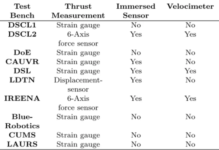
We can notice from Table 1 that most of the test benches are equipped with strain gauge sensors for measuring the thrust, this is related to their simplicity of implementa-tion and their cost which is less expensive then a 6-axis force sensor (DSL2 and IREENA) or displacement sensor (LDTN). Also, most test benches immerse the force sensor in the water in order to make a direct measurement of the thrust force, this choice requires some means of sealing the sensor which may inadvertently affect the sensor perfor-mance. Some test benches are equipped with additional sensors (e.g: velocimeter) for measuring the velocity of the fluid (DSCL2,DSL and IREENA), this makes it pos-sible to identify other parameters possibly influencing the thrust measurements and thus improve the accuracy of the thruster model, but this will significantly increase the cost of the test bench.
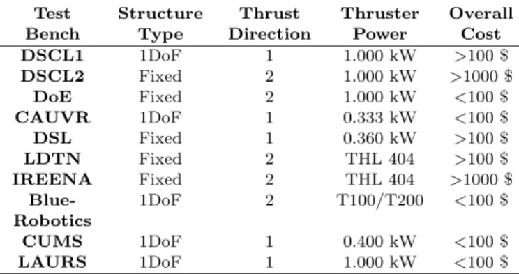
The structure comparison in Table 2 shows that there are two approaches, the first is the use of a fixed structure
Table 1. Comparison of test bench measure-ment sensors
Test Thrust Immersed Velocimeter
Bench Measurement Sensor
DSCL1 Strain gauge No No
DSCL2 6-Axis Yes Yes
force sensor
DoE Strain gauge No No
CAUVR Strain gauge Yes No
DSL Strain gauge Yes Yes
LDTN Displacement- Yes No
sensor
IREENA 6-Axis Yes Yes
force sensor
Blue- Strain gauge No No
Robotics
CUMS Strain gauge No No
that does not allow any degree of freedom, however the advantage of this solution is the measurement of the thrust force in both directions using a 6-axis load cell without changing the thruster configuration. The second is to use a structure that allows movement in one degree of freedom, the force sensor is removed out of the water so as to avoid the necessity of sealing the sensor, however the measurement of thrust is only in one direction.
The cost of a test bench depends on the following param-eters:
• The type and variety of sensors employed (strain gauge, 6 axis, displacement, tachometer and velocime-ter).
• The type of material used in the structure part. • The size of the thruster under test.
• The dimensions of the test tank.
The objective of this comparison is to have a general overview of the technical choices and criteria that must be taken into consideration for the realization of a test bench destined for the identification or control of an underwater thruster.
4. DESCRIPTION OF THE TEST BENCH REALIZED Our goal is to build a low-cost test bench that will allow us to identify and control an underwater thruster that will also be low-cost, this thruster is designed and realized by us and will be integrated in our future underwater vehicle. The desired requirements for the test bench to be designed and realised are as follows:
• The test bench will be used for the identification of small thrusters (<1kWatt), the tank must be of rectangular form to allow for the inclusion of a side observation window,
• The test structure must be adapted to the tank, with low drag so as not to impact on the water flow, simple to construct, and able to measure the thrust in both directions,
• A low-cost thruster with a ducted propeller and a sealed brushless motor, that is easy to build and to control, will be mounted to the test structure, • The use of a force and current sensor that can be
interfaced to an acquisition card should be used for digitizing measurements.
According to the specifications mentioned above, we were inspired by the BlueRobotics test bench, that is simple
Table 2. Structure comparison of test benches
Test Structure Thrust Thruster Overall
Bench Type Direction Power Cost
DSCL1 1DoF 1 1.000 kW >100 $ DSCL2 Fixed 2 1.000 kW >1000 $ DoE Fixed 2 1.000 kW <100 $ CAUVR 1DoF 1 0.333 kW <100 $ DSL Fixed 1 0.360 kW >100 $ LDTN Fixed 2 THL 404 >100 $ IREENA Fixed 2 THL 404 >1000 $ Blue- 1DoF 2 T100/T200 <100 $ Robotics CUMS 1DoF 1 0.400 kW <100 $ LAURS 1DoF 1 1.000 kW <100 $
Fig. 11. Test bench used for identification
Fig. 12. The thruster assembly
and easy to build, destined for testing small thrusters, the supporting structure is (L) shaped form, and the entire structure is easily transportable. In the following paragraphs we will present each constituent element: 4.1 Test Tank
The dimensions of the tank are: 800x325x415 mm for L, W and H, respectively. An opening on the side allows to observe the thruster during its immersion in water as shown in Fig. 11. The tank is designed for small thruster tests, therefore, its dimensions are sufficient to center the thruster so as not to impose a boundary wall effect (force feedback) on the measurement of the thrust.
4.2 Support Structure
It is composed of a support of L-shaped form, with a vertical section of 320 mm immersed on which the thruster will be fixed and another horizontal section of 220 mm that will transfer the force onto the force sensor located outside the tank. This support allows the rotational movement around an axis of 8 mm and fixed by bearings.
4.3 Propulsion
The thruster that we want to identify was designed by us. It is based on an integrated brushless motor, reference A2212. The fairing of the thruster and its 3 bladed propeller are made by a 3D printer. Table 3 shows the dimensions of the thruster and Fig. 12 shows its assembly.
Table 3. Thruster Dimensions
Propeller Fairing/Duct
Diameter 66 mm 70 mm
Length 20 mm 98 mm
Blades 3 –
Material ABS ABS
4.4 Electronic Components
A 5 kg strain gauge load cell is used to measure the thrust force generated. The principle of measurement with
Fig. 13. Schematic of the developed test bench.
a strain gauge is based on a Wheatstone bridge with variable resistors that are sensitive to deformation of the load cell. The variation of the voltage at the bridge is very small, so it is necessary to use an amplifier. A circuit which integrates an amplifier and a converter with a resolution of 24 bits (HX711) was used to make the sampling and digitization of the thrust force, then transmit it in numerical format to an acquisition card.
The current absorbed by the thruster is measured by an ACS712 Hall effect current sensor, it produces an analog output that is measured by the Analog to Digital Converters (ADC) of the acquisition card.
An Electronic Speed Controller (ESC) of 30 A is used to control the thruster. Fig. 13 shows the schematic diagram that explains the acquisition system.
Table 4 shows the components used in the realization of the test bench and their approximate prices. The total price of the bench does not exceed 100$, which makes it low-cost and the results that will be presented in the next section will show its efficiency.
Table 4. Itemised list and costs of constituent parts used to build the test bench
Items Type Approx. Price
Power Supply ATX 20 $
Acquisition Card Arduino 10 $
Force Sensor 5 kg Strain gauge 05 $
24 bits ADC HX711 03 $
Current Sensor ACS712 30A 05 $
Support Structure Stainless Steel 10 $
Other accessories Wires 10 $
Water Tank Recovery Article 00 $
Overall Cost 70 $
5. RESULTS AND COMPARISONS 5.1 Results
To characterise the thruster we need to obtain the mea-surements concerning the thrust force generated and the corresponding current consumed by the the thruster,
Fig. 14. Thrust force generated by the thruster.
Fig. 15. Current consumed by thruster for forward/reverse directions.
across the speed range of the thruster from 0 to 100% which corresponds to a Pulse Width Modulation (PWM) from 1000 to 2000 µs.
Fig. 14 shows the thrust force curve generated in the forward and reverse directions. We notice that there are 3 operating zones: the dead zone in which the thruster doesn’t produce force and is of the order of 50 us, then a linear zone which is the operating zone between 50 and 1800 us, but beyond this zone the thruster enters into a saturation zone where the thrust force remains constant despite the increase of the PWM signal. The thrust force generated in the forward and reverse direction is approximately 12.25 and 10.78 Newton respectively which is equivalent to 1.25 and 1.10 Kgf.
The current consumed by the thruster is shown in Fig. 15, we note that the maximum current reaches 21 A which is equivalent to a power of about 250 Watts under a supply voltage of 12 Volts.
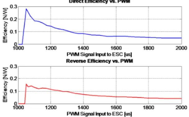
In Fig. 16 the curve shows the efficiency of the thruster, where efficiency can be determined from the thrust force generated with respect to the power consumed. We note that the efficiency in the forward direction is 0.28 New-ton/Watt which is greater than in the reverse direction which is equal to 0.15 Newton/Watt.
Fig. 17 shows that the relationship between current and thrust force has a quadratic form and this implies that the Torque-Thrust relationship is also quadratic because the torque is proportional to the current.
Fig. 16. Thruster efficiency.
Fig. 17. Current vs. Thrust. 5.2 Comparison
In order to validate the thruster that we have built and analyzed with the test bench, we will make a comparison with another thruster that is supposed to have similar per-formances. This thruster is the T100 from BlueRobotics (BlueRobotics (2019)), The Table 5 shows the main fea-tures of the comparison.
Table 5. Comparison with T100 Thruster
Electrical/Physical T100 Our Thruster
/Performance
Max Forward Thrust 2.36 kgf 1.25 kgf (12.25 N) Max Reverse Thrust 1.85 kgf 1.10 kgf (10.78 N) Min Thrust 0.01 kgf 0.05 kgf (0.049 N) Rotational Speed 300-4200 rev/min 700-15000 rev/min
Operating Voltage 6-16 Volts 12 Volts
Max Current 12.5 Amps 21.0 Amps
Max Power 136 Watts 250 Watts
Length 102 mm 98 mm Diameter 100 mm 70 mm Weight 295 gr 152 gr Propeller Diameter 76 mm 66 mm Cost(without ESC) 119 $ 45 $ Cost(with ESC) 144 $ 65 $ 6. CONCLUSION
We have presented in this article a low-cost test bench destined for the identification of an underwater thruster, this bench was realized by taking into account the ad-vantages and disadad-vantages of existing test benches. The thruster that we have tested is a thruster designed and
constructed by us using a 3D printing technique. The curve presented in Fig. 14 can be transformed into a polynomial of N degrees by neglecting the higher order dynamics of the thruster. This polynomial will be integrated in the mathematical model of an underwater vehicle in order to get a simulation behavior closer to the reality so that the control laws can be validated before they are implemented on the vehicle. The comparison in Table 5 shows that the thruster that we have realized and tested using the test bench described above, does not perform as well as the T100 but its performance is nevertheless satisfactory given its cost. It must be taken into account that the respective tests are made using different test benches, and that the T100 values used in the comparison are values obtained from the manufacturer’s data sheet (BlueRobotics (2019)).
REFERENCES
Aras, M., Abdullah, S., A.Rahman, and Aziz, M. (2013a). Thruster modeling for underwater vehicle using system identification method. International Journal of Ad-vanced Robotic Systems, 10, 252–264.
Bachmayer, R., Whitcomb, L., and Grosenbaugh, M. (1999). Development, comparison, and preliminary experimental validation of nonlinear dynamic thruster models. IEEE Journal of Oceanic Engineering, 24, 481– 494.
BlueRobotics (2019). BlueRobotics test bench. https:// www.bluerobotics.com.
Cody, S. (2003). An Experimental Study of the Response of Small Tunnel Thrusters to Triangular and Square Wave Inputs. Master’s thesis, Naval Postgraduate School, Monterey, Canada.
Cooke, J. (1989). Incorporating Thruster Dynamics in the Control of an Underwater Vehicle. Master’s thesis, MIT, USA.
Deniellou, L., Gallou, Y., Gourmelen, P., and Seube, N. (1998). Force control of underwater thrusters with application to auv motion control. IEEE Oceanic Engi-neering Society, 2.
Guibert, C. (2005). Modelisation et commande en pous´ee de moteurs `a courant alternatifs en propulsion navale. Ph.D. thesis, Universit´e de Nantes.
Healey, A., Rock, S., Cody, S., Miles, D., and Brown, J. (1995). Toward an improved understanding of thruster dynamics for underwater vehicles. IEEE Journal of Oceanic Engineering, 20, 354–361.
Juca, J., Saito, M., CezarAdamowski, J., Takase, F., and Maruyama, N. (2012). Modelling and identification of yaw motion of an open-frame underwater robot. Journal of Intelligent and Robotic Systems, 66, 37–56.
Muljowidodo, K., Adi, N., Prayogo, N., and Budiyono, A. (2009). Design and testing of underwater thruster for shrimp rov-itb. Indian Journal of Marine Sciences, 38, 232–237.
Whitcom, L. and Yoerger, D. (1999). Development, comparison, and preliminary experimental validation of nonlinear dynamic thruster models. IEEE Journal of Oceanic Engineering, 24, 481–494.
Yang, R., Clement, B., Mansour, A., Li, M., and Wu, N. (2015). Modeling of a complex-shaped underwater vehicle for robust control scheme. Journal of Intelligent and Robotic Systems.