DEA THESIS
Louvigny Yannick
Preliminary design of twin-cylinder engines
Supervisor: Professor P. Duysinx
Academic year 2007-2008
August 2008
This thesis is submitted in partial fulfillment of the requirements for the Degree
of Advanced Studies in Applied Sciences
Abstract
This report deals with the preliminary design of a twin-cylinder engine. The goal of the work is not to make the detailed design of the engine but to draw the main characteristics of each kind of engine and to investigate which configuration of twin-cylinder engine matches in the best way to given requirements.
A simple model is developed from the motion equations of the rotating and oscillating parts of piston engine. This model allows calculating the values of the inertia forces and moments for each angular position of the crankshaft. Different configurations of single-cylinder and twin-cylinder engines (including in-line or boxer, in-phase or out-of-phase motion of the piston) are considered. All of these configurations are characterized by their own set of forces and moments.
As the free forces and moments are responsible for engine vibrations and thus vibrations of the vehicle and its passengers, a set of balancing solutions (modification of the crankshaft, addition of first or second order balance shafts) is considered to reduce these loads. This is the balancing of the engine. Great reductions of forces and moments can be obtained with more or less complex solutions. From a design point of view, the next step is to determine what level of vibration is acceptable and which solutions permit to reach this level. A model of a classical four-cylinder engine is made in order to serve as a reference for the comparison of the different configurations of twin-cylinder engine.
In addition to the inertia forces, the combustion of the fuel inside the cylinder produces also forces and moments in the engine. To estimate the total forces and moments created by the engine, the gas pressure force is calculated for each configuration of the engine.
The last step of this preliminary design consists in investigating the influence of design parameters that can impact the balancing of the engine. A sensitivity analysis is made with different design parameters of the engine (i.e. the mass of the piston, the mass and length of the connecting rod…) This analysis permits to know, depending of the configuration of the engine, which characteristics will require a greater attention during the design phases.
Acknowledgement
First of all, I would like to express my gratitude to my supervisors, Professors Pierre Duysinx and Jean-Luc Bozet for giving me the opportunity to write this report and to work with them during these two years.
I wish also to thank Mr. Ernst Breuer, manager of BTD, who is the instigator of this project, for the time and the data, he shared with us.
I would like to thank Professor André Jamoulle for his knowledge and his precious advices. Finally, I would like to express my gratitude to Cendrine and to my Family for their presence and support all theses years.
Table of contents
Abstract ... 2
Acknowledgement... 3
Table of contents ... 4
1. Introduction and objectives ... 6
2. Literature review ... 8
3. Modeling of engines... 11
3.1. Engine and crankshaft configurations ... 11
3.1.1. Engines ... 11 3.1.2. Crankshaft ... 12 3.1.3. Strokes... 14 3.1.4. Balance shafts... 15 3.2. Modeling ... 16 3.2.1. Coordinate system ... 16 3.2.2. Assumptions ... 17 3.2.3. Equations... 18
4. Evaluation and balance of inertia forces ... 23
4.1. Approximation of equations... 23
4.2. Shorter stroke single-cylinder engine... 24
4.2.1. Reference data (case 1) ... 24
4.2.2. Optimization of the crankshaft (case 2) ... 28
4.2.3. Balance shafts... 31
4.2.4. Summary ... 40
4.3. Longer stroke single-cylinder engine... 42
4.4. Shorter stroke twin-cylinder in-line engine, in-phase arrangement ... 44
4.4.1. Reference data (case 1) ... 44
4.4.2. Optimization of the crankshaft (case 2) ... 45
4.4.3. Balance shafts... 47
4.4.4. Summary ... 51
4.5. Longer stroke twin-cylinder in-line engine, in-phase arrangement ... 53
4.6. Shorter stroke twin-cylinder in-line engine, out-of-phase arrangement ... 55
4.6.1. Reference data (case 1) ... 55
4.6.2. Optimization of the crankshaft (case 2) ... 56
4.6.3. Balance shafts... 58
4.6.4. Summary ... 60
4.7. Longer stroke twin-cylinder in-line engine, out-of-phase arrangement... 62
4.8. Shorter stroke twin-cylinder boxer engine, out-of-phase arrangement... 64
4.8.1. Reference data (case 1) ... 64
4.8.2. Optimized crank and balance shafts... 64
4.8.3. Summary ... 65
4.9. Longer stroke twin-cylinder boxer engine, out-of-phase arrangement ... 67
4.10. Shorter stroke twin-cylinder boxer engine, in-phase arrangement ... 69
4.11. Longer stroke twin-cylinder boxer engine, in-phase arrangement... 71
5. Effect of the gas pressure ... 73
5.1. Single-cylinder engine... 73
5.2. In-line twin-cylinder in-phase engine ... 77
5.3. In-line twin-cylinder out-of-phase engine... 83
5.3.1. Shorter stroke ... 83
5.3.2. Longer stroke... 85
5.4. Boxer twin-cylinder out-of-phase engine... 86
5.4.1. Shorter stroke ... 86
5.4.2. Longer stroke... 87
5.5. Boxer twin-cylinder in-phase engine ... 87
5.5.1. Shorter stroke ... 87
5.5.2. Longer stroke... 87
6. Comparison of twin-cylinder engines ... 88
6.1. Vibration point of view ... 88
6.1.1. Comparison of different twin-cylinder arrangements ... 88
6.1.2. Comparison with a four-cylinder engine... 90
6.2. Gas pressure effect point of view... 94
7. Sensitivity analysis... 96
7.1. Mass of the piston ... 96
7.1.1. In-phase in-line twin-cylinder engine ... 96
7.1.2. Out-of-phase in-line twin-cylinder engine ... 98
7.1.3. Out-of-phase twin-cylinder boxer engine ... 99
7.1.4. In-phase twin-cylinder boxer engine... 100
7.2. Mass of the connecting rod ... 101
7.2.1. In-phase in-line twin-cylinder engine ... 101
7.2.2. Out-of-phase in-line twin-cylinder engine ... 103
7.2.3. Out-of-phase twin-cylinder boxer engine ... 104
7.2.4. In-phase twin-cylinder boxer engine... 105
7.3. Length of the connecting rod ... 106
7.3.1. In-phase in-line twin-cylinder engine ... 106
7.3.2. Out-of-phase in-line twin-cylinder engine ... 108
7.3.3. Out-of-phase twin-cylinder boxer engine ... 109
7.3.4. In-phase twin-cylinder boxer engine... 110
7.4. Distance between bore centers ... 111
7.4.1. In-phase in-line twin-cylinder engine ... 111
7.4.2. Out-of-phase in-line twin-cylinder engine ... 112
7.4.3. Out-of-phase twin-cylinder boxer engine ... 113
7.4.4. In-phase twin-cylinder boxer engine... 114
7.5. Conclusions ... 115
8. Conclusions ... 116
References ... 121
Appendix ... 123
Appendix A: Graphics of forces and moments for the different configurations of twin-cylinder engine ... 123
1.Introduction and objectives
“The climate is changing”. “Pollution produced by human activities endangers the equilibrium of the planet”. Facing environmental and energy resources depletion challenges, automotive industry has to improve the fuel economy of new vehicles and reduce their polluting emissions. Transport of goods and people is an important source of CO2 emissions.
In particular, passenger cars that are widespread in our modern countries are responsible for an important amount of CO2 and pollutants. To reduce pollution from those cars, there are two
major solutions: a more rational use of the vehicle (carpooling…) and making cleaner cars. To make cleaner vehicle, a strategy that is widely used nowadays is the downsizing i.e. replacing a big engine by a smaller one with a higher specific power. This has become possible thanks to turbochargers and direct injection. This tendency will be particularly reinforced with hybrid electric cars.
With the high specific power (horsepower per liter of engine displacement) achieved nowadays in common cars (more than 100 hp/l for gasoline or 85 hp/l for diesel), small twin-cylinder engines regain interests for use in urban cars and as prime movers in hybrid electric cars. The twin-cylinder has the advantage of needing fewer parts than a four-cylinder of the same displacement and thus being less expensive [HEISLER 1999]. Moreover some parts (piston, connecting rod, valve…) can be common with some four or six cylinders engines of the same line. Reducing the number of cylinders sounds also more interesting than reducing the volume of cylinders because of the more delicate design of small cylinders. On the other hand, the difficulty with engine having few cylinders (three or less) comes from the balancing of the engine.
A perfectly balanced engine is one in which the relative motion of the component parts do not set up an accumulation of forces that tends to make the engine shake and rock. Hence, if the perfectly balance engine were to be suspended freely in space, no vibration or other movement would be observed. Therefore, in theory, such an engine could be attached directly to its support frame. Conversely, a partially balanced engine requires some sort of suspension mounting to isolate the engine from its support frame to prevent any of the unbalanced reaction movement being transmitted through to the vehicle’s chassis and body [HEISLER 1995].
So, the main goal of this study is to investigate the preliminary design of a twin-cylinder engine. This work is made in cooperation with BTD (Breuer technical development). BTD is one of Belgium's leading developers of modern engines, including both high-performance competition engines and series production engines [BTD 2008]. BTD has provided the technical data of the engine (geometry of the cylinder parts, pressure inside the cylinder…). The different steps and intermediate objectives of this work are:
• Considering and comparing different configurations of twin-cylinder engine to emphasize the advantages and drawbacks of each ones. The differences between these configurations include the relative position of the cylinders (in-line or opposed), the shape of the crankshaft (in-phase or out-of-phase).
• Computing the forces and moments inside the engines. The calculations are based on simplified models of the engines developed from the equations of motion of
• Balancing the engines. This is made by using different methods alone or in conjunction. These methods are namely the optimization of the crankshaft counterweights, the addition of one or two first or second order balance shafts.
• Introducing in the simulation the effect of the gas pressure inside the cylinder. This allows calculating the forces and moments due to the combustion, their effect on the balancing of the engine and the engine torque (instantaneous and average).
• Comparing the different twin-cylinder configurations with a classical four-cylinder engine in order to determine which configuration offers an equivalent comfort in terms of vibration but remains simple enough from a design point of view.
• Studying the influence of the stroke on the forces and moments generated by the engine. Two different strokes are included in the engine arrangements.
• Making a sensitivity analysis on the design parameters (i.e. mass of the piston, mass and length of the connecting rod and distance between the bore centers) in order to determine the most interesting parameters to modify to improve the balancing of the engine.
At the end of this approach, we would be able to provide guidelines to help designers to determine which configuration of twin-cylinder engine is adapted for their specific application. And we would know which parameters will be critical in the engine conception.
2.Literature review
New legislation and environmental considerations have pushed the car companies to improve the efficiency, and thus the specific power of their engines. Thanks to the high specific power reached nowadays by modern engines (gasoline or diesel), very small engines (displacements smaller than 1000 cc) are powerful enough to be operated in small urban cars or used as prime movers in hybrid cars. To build so small engines, there are two choices possible: using a traditional four-cylinder arrangement with small size cylinders or using fewer cylinders (two or three cylinders).
Reducing the volume of each cylinder is a hard task because the design of small mobile parts is very difficult and the efficiency becomes smaller (the friction to power ratio is increasing). Moreover, an engine with few cylinders has the advantage of needing fewer parts than a four-cylinder of the same displacement so it will be easier to build, to maintain and to repair. It will also be less expensive and shorter [HEISLER 1999]. On the other hand, the difficulty with engine having three or less cylinders comes from its balancing. Today, many car manufacturers are developing small engines with two or three cylinders:
Volkswagen [VW 2008] uses a gasoline three-cylinder engine (1198 cc offering different choices of power: 40 kW, 44 kW and 51 kW) or a diesel three-cylinders engine (1422 cc, 51 kW or 59 kW) in the smallest cars of the VW company (VW Fox, VW Polo, Seat Ibiza, Skoda Fabia…).
Hyundai [HYUNDAI 2008] introduces a three-cylinder diesel engine (1120 cc, 55 kW) in the Hyundai I10 (this engine is also mounted in the Kia Picanto).
Toyota [TOYOTA 2008] offers a three-cylinder gasoline engine (998 cc, 50kW) in the Toyota Aygo, Yaris and probably in the future Toyota IQ (this engine is also mounted in the Peugeot 107 and Citroen C1).
Daihatsu [DAIHATSU 2008], the specialist of the urban cars, offers a three-cylinder gasoline engine (989 cc, 43 kW) in the Daihatsu Trevis. While the Daihatsu Sirion and Cuore use the Toyota three-cylinder gasoline engine (998 cc, 50kW).
Opel [OPEL 2008] makes also a three-cylinder gasoline engine (998cc, 44kW) in the Opel Corsa and Agila.
And last but not least, the Smart [SMART 2008], built by Daimler, uses a complete range of three-cylinder engines, from diesel engine (799 cc, 33 kW) to gasoline engines without turbo compressor (999 cc, 45 kW or 52 kW) or equipped with a turbo compressor (999 cc, 62 kW or 72 kW).
Nevertheless, these two-cylinder or three-cylinder engines are not naturally balanced. So, in a basic configuration, they are noisier and more vibrating than an equivalent four-cylinder engine. Today, ride comfort and noise cancellation are crucial in the automotive industry. Even the most basic and low-cost cars of a manufacturer range have to be comfortable and well equipped. So the balancing of these small engines is at the center of the car manufacturers researches.
The basic notions for the calculation of the inertia forces and for the balancing of the more classical configurations of engine are well-known for a long time and are described in different reference textbooks [MAASS 1981, HEISLER 1995, BOSCH 2000]. But the subject is still studied nowadays, in particular, the more specific arrangements (boxer engine, Vee-engine with unusual angle between cylinder rows).
Grigoryev, Vasilyev and Dolgov [GRIGORYEV 2006, VASILYEV 2007] develop a method to determine which arrangement (vee-angle, shape of the crankshaft…) of a given engine gives the minimum mass and vibrations of the engine.
But these models only take into account the piston primary motion (longitudinal motion). The secondary motions of the piston (lateral and rotational motion) are neglected. In practice, due to a small clearance between the piston and the cylinder wall, there are always lateral and rotational motions of the piston. There is a side thrust force induced by the connecting rod and the direction of this force changes periodically. So the piston moves from one side to the opposite side of the cylinder wall and collides with it. This phenomenon is called “piston slap” and is responsible for unwanted noise and vibration. Cho et al. [CHO 2002] develop a simple model to estimate the impact force induced by the piston slap. To validate their model, they compare the numerical results with measured vibration responses, the model gives good predictions below 500 Hz but there are some discordances above 500 Hz.
Engine vibrations are not only due to the inertia forces, the fuel combustion inside the cylinders is also responsible for vibrations and noises. In particular, if the combustion is unequal in the different cylinders, the individual torque produced by each cylinder will be different and that will produce torsional vibrations of the crankshaft and risk of breakdown. Östman and Toivonen [ÖSTMAN 2008] suggest a method to reduce these torsional vibrations. The method uses the angular speed sensor of the crankshaft to detect unbalance torque distribution. The angular acceleration of the crankshaft allows calculating the net torque produces by each cylinder. The variations of torque are corrected by adjustment of the fuel injection in the right cylinders. The technique is tested on a real engine and a 90 % reduction of the amplitude of the torsional vibrations is achieved.
Chauvin et al. [CHAUVIN 2006] make the same kind of unbalance torque distribution measurements. In the first part of their study, they present also a method based on the crankshaft angular speed. But in the second part, they measure the air fuel ratio injected in each cylinder to control the combustion torque.
It appears that one the most important components of the engine is the crankshaft. Of course, it is one of the components that transform the linear motion of the pistons into a rotational motion. But it is also used to carry the counterweights that balance a part of the inertia forces and moments. So to achieve a very small vibration level, a careful attention has to be accorded to the design of the crankshaft. That is the reason why there are still so much scientific studies dedicated to the crankshaft and its influence on the balancing of the engine. Zouroufi and Fatemi [ZOUROUFI 2005] present a literature reviews on fatigue performance evaluation and comparisons of different manufacturing procedure of crankshaft. The crankshafts specifications, operating conditions and sources of failures are first reviewed, then the design and the manufacturing procedures of the crankshafts are discussed. Geometric optimization and cost analysis are also briefly presented.
Bayrakçeken et al. [BAYRAKÇEKEN 2007] study the failure causes of several crankshafts of single-cylinder diesel engines.
The next step consists in building a complete model of the engine including the crankshaft and all the mobile parts to study the dynamic and the vibrations of the engine. Boysal and Rahnejat [BOYSAL 1997] make a multi-body numerical nonlinear dynamic model of a single cylinder engine. The model includes a piston, connecting rod, crankshaft, flywheel, timing gear, torsional damper and crankshaft main journal bearings. The model is parameterized to allow testing of different designs. The results obtained provide dynamic response of all parts, torsional vibrations of the crankshaft and whirls of journal bearings. The numerical solutions agree with analytical solutions and experimental tests.
Mourelatos [MOURELATOS 2001] takes an interest in the same problem. He does a complete engine model that couples the crankshaft dynamics, the main bearings hydrodynamic lubrication and the engine block stiffness. The method is applied to a five-cylinder in-line engine. Computed vibrations of the crankshaft are compared with measured response and the correlation is very good. A V6 engine is also simulated in order to demonstrate the methodology capability to fit to different configurations.
Metallidis and Natsiavas [METALLIDIS 2003] present models of single-cylinder and multi-cylinder engines that take into account the dependence of the engine moment of inertia on the crankshaft rotation. The driving and the resisting torques depend also on the crankshaft rotation that leads to dynamic models with non-linear equations of motion. First, an analytical solution is searched for a linearized version of the equations, and then numerical results are given for linear and non-linear models. And finally, response of the system in case of engine misfire is investigated.
The balancing of the engine is never perfect, so it remains always some unwanted vibrations. Then, another important task is to minimize the vibrations that are transmitted from the engine to the rest of the vehicle. That is one function of the engine mounts.
Snyman et al. [SNYMAN 1995] study the minimization of the transmission of engine vibration in the case of a mounted four-cylinder engine. This is an optimization problem and the minimization of the motion at the mounting position is the objective function. The position and the phase angle of some balancing masses are the design variable. The authors apply Snyman’s dynamic optimization algorithm (LFOP1B) successfully to this problem. Foumani et al. [FOUMANI 2003] develop an experimental/numerical technique for engine mounts optimization. Their method is based on experimental results and does not require complicated mathematical models of the vehicle. They use only a quarter car model composed of three subsystems (chassis, mount and engine). The mount is the part to be optimized, the engine is assumed rigid and its inertia is known, and the response of the chassis is deduced from experiments
All these works and studies illustrate that actual car designers worry about minimizing noise and vibrations in modern car. For this purpose, the boxer engine shows real interests because its inertia forces are naturally balanced.
3.Modeling of engines
We describe in this section the different configurations of engines, crankshafts, strokes and balance shafts that are considered in this report. We also describe the set of axes, the models and establish the motion equations we use.
3.1. Engine and crankshaft configurations
3.1.1. Engines
We focus on two different types of engine: in-line engine and boxer engine.
In the in-line engine, also designated as straight engine, cylinders are arranged consecutively in one row (figure 1). This is by far the most common configuration used for three, four and five cylinders engine mounted in small and medium-size cars. The reasons are that in-line engines are considerably easier to build than any other equivalent engine arrangements because the cylinder bank can be milled from a single metal casting and require fewer cylinder heads and camshafts [WIKIPEDIA 2007]. Moreover, it can be mounted in different directions, lengthways or transversely, and could accept an inclination, which is important for small engine bay and safety considerations.
Figure 1: Four-cylinder in-line engine [CARBIBLES 2007]
Boxer engine (figure 2), also known as horizontally opposed engine or flat engine, is more compact than in-line engine, and has a lower center of gravity than any other common
configurations which gives a better stability and control to the vehicle. This type of engine, however, is wider than more traditional arrangement and is more expensive to build. The extra width may cause problems fitting the engine into the engine bay of a front engine car owing to the interference with the steering wheels. This type of engine is used by car manufacturers like Subaru or Porsche but also for motorbike by manufacturers like BMW.
Figure 2: Six-cylinder boxer engine [PORSCHE 2007]
3.1.2. Crankshaft
For in-line engines, we consider two arrangements of the crankshaft. The first one has its two crankpins, one for each connecting rod, on the same line grid, which means that the two pistons are moving in phase (reaching the top dead center (TDC) and bottom dead center (BDC) at the same time), so it is referred later as the in-phase arrangement (see figure 3). In the second configuration of the crankshaft, there is a phase shift of 180 degrees between the two crankpins; this phase shift leads to an out-of-phase movement of the piston (one piston
reaches the TDC when the second reaches the BDC), so it is referred later as the out-of-phase arrangement (see figure 4).
Figure 3: In-phase configuration (in-line engine)
Figure 4: Out-of-phase configuration (in-line engine)
3.1.2.1. Remark 1
We consider for boxer engines, the same arrangements of the crankshaft, but it is important to notice that in this case, the in-phase arrangement (two pistons moving in phase) corresponds to the crankshaft having a phase shift between its two crankpins (figure 5) and the out-of-phase arrangement corresponds to the crankshaft with the crankpins on the same line grid (figure 6). The names in-phase and out-of-phase relate to the relative position of the
pistons and not to the relative position of the crankpins.
Figure 6: Out-of-phase configuration (boxer engine)
Figure 5: In-phase configuration (boxer engine)
3.1.2.2. Remark 2
We only consider here crankshafts having two crankpins. Nevertheless, it is possible to use a single long crankpin instead of two crankpins on the same line grid (figure 7) for the in-phase in-line engine or for the out-of-phase boxer engine. At this point of the modeling, we choose not to focus on single crankpin crankshaft because it does not match with the modeling of the counterweights. We prefer to have the counterweight in front of the corresponding piston in order to minimize free moments due to the offset between the forces generated by the piston and the forces generated by the counterweight. This can be achieved practically by dividing
the mass of the counterweight between the two corresponding crank arms (figure 8), which is impossible for two connecting rods having only one crankpin.
Since the cylinders of the boxer engine are not on the same side of the crankshaft, the distance between the bore centers is not restrained by the cylinders size. So this distance could be reduced. In the case of the out-of-phase boxer engine, we could go further and put the two cylinders on the same axis and use one connecting rod with a big end in shape of fork and one normal connecting rod (figure 9). We will come back later to these solutions if they show some potential interest for our engines.
Figure 8: Position of the counterweights for a crankshaft with two crankpins
Figure 7: Position of the counterweights for a crankshaft with only one crankpin
Figure 9: Fork connecting rod for out-of-phase boxer engine
3.1.3. Strokes
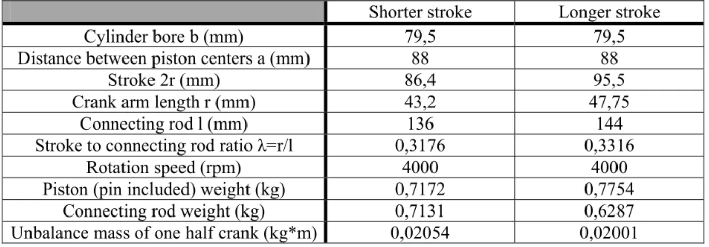
For the four configurations described previously (two engines and two crankshafts), we use, in this study, two different sets of data provided by Breuer Technical Development (see table 1 and figure 10). One corresponds to a stroke of 86,4mm that we call shorter stroke engine (if we compare the stroke to the cylinder bore 79,5mm, it is still a long stroke engine) while the other one with a stroke of 95,5mm is called longer stroke engine.
Shorter stroke Longer stroke
Cylinder bore b (mm) 79,5 79,5
Distance between piston centers a (mm) 88 88
Stroke 2r (mm) 86,4 95,5
Crank arm length r (mm) 43,2 47,75
Connecting rod l (mm) 136 144
Stroke to connecting rod ratio λ=r/l 0,3176 0,3316
Rotation speed (rpm) 4000 4000
Piston (pin included) weight (kg) 0,7172 0,7754
Connecting rod weight (kg) 0,7131 0,6287
Unbalance mass of one half crank (kg*m) 0,02054 0,02001 Table 1: Reference data of the shorter and longer stoke engines
Figure 10: Geometry and data of the engines
3.1.4. Balance shafts
We also consider the possibility to use one or several balance shafts to counteract some of the residual forces. These shafts are designed to balance forces of one defined order. For the first order forces, the balance shafts should rotate at the same speed that the crankshaft whereas they should revolve at twice the crankshaft speed to counteract second order forces etc. The precise speed and phase shift of the balance shafts are obtained by connecting these shafts to the timing chain or belt with sprocket wheels or pulleys of appropriate diameters (i.e. half size of the crankshaft sprocket wheel to have the double speed).
The balance shafts are realized with an unbalance mass so when they revolve, they produce a rotating force. To balance the reciprocating force of the piston, the rotating force of the balance shaft can be transformed into an oscillating force by using two counterrotative balance shafts (see figure 11) . The component in the direction perpendicular to the cylinder bank (Y-direction) of the force generated by one balance shaft is compensated by the force generated by the second balance shaft. The two balance shafts have to be placed symmetrically on each side of the cylinder bank in order to produce no free moments.
Figure 11: Two balance shafts balancing piston force (one order)
If we use balance shafts to counteract first order forces or moments, it is possible to use only one balance shaft. Because one of the two balances shaft rotates in the same direction that the crankshaft, so its unbalance mass can be added to the crank one. Thus, we keep only the modified crankshaft and the counterrotative balance shaft, the problem with that method is that the forces generated in the direction of the piston motion (X-direction) by both shafts and the piston are not aligned, neither the Y-forces so they produce rolling moments.
In the same manner, to counteract second order forces, we can use only one balance shaft. But, as the rotation speed of the balance shaft and the crankshaft are different, the second order Y-forces generated by the balance shaft can not be compensated by the unbalance mass of the crank. So we can decrease second order X-forces at the price of an increase in perpendicular forces and rolling moments.
3.2. Modeling
3.2.1. Coordinate system
In this study, the most convenient coordinate systems are right-handed Cartesian coordinate systems. We choose to use the direction of the cylinder as X-axis and the direction of the crankshaft as Z-axis, the direction of the Y-axis is deduced from the two other axes using the right hand rule (figures 12 & 13).
Figure 12: Coordinate system for the boxer engine
Figure 13: Coordinate system for the in-line engine
3.2.2. Assumptions
In this preliminary study, we make a few assumptions that are commonly accepted for the calculation of inertia forces and moments in engine.
We consider the engine as a rigid body mechanism. We do not take into account the flexibility of the different parts of the engine. The engine is seen as the sum of uncoupled cylinder sub-systems i.e. the forces generated by each piston and each crankshaft counterweight are calculated separately. Then, all single forces are summed to give the total forces and moments that are produced by the engine.
We separate the parts that experience a reciprocating movement (piston, gudgeon pin) and the ones that undergo a rotating movement (crankshaft, counterweight). The case of the connecting rod is more difficult because it has both an oscillating and rotating movements, so we make the assumption that one third of the connecting rod mass (small end) is a reciprocating mass and two third (big end) is a rotating mass [BOSCH 2000, pp. 397].
We suppose that all the forces in the Z-direction (direction of the crankshaft) are equal to zero.
We neglect the forces of the pistons against the cylinder wall or sleeve (piston slap).
We suppose also that the forces generated by the rotating mass related to one cylinder and the forces generated by the reciprocating mass of the same cylinder are included in the same Z-plane.
The oscillating inertia forces could be calculated using some relationships between the angle of the crank θ, the pivoting angle of the connecting rod and the stroke to connecting rod ratio λ (= r/l). All theses relationships can be represented in the form of a Fourier series. In this series, we neglect the higher order terms and some coefficients if it leads to an error smaller than 0,1%.
3.2.3. Equations
3.2.3.1. For one cylinder
We start with writing the equations of the piston motion (s), obtained by projection on the vertical (equation (1)) and horizontal (equation (2)) axes of the figure 14 [GOLINVAL 2001]. By deleting the angle φ from the relations (1) and (2), the equation (3) that links the piston motion to the crankshaft angle is obtained. This relation can be linearized (equation (4)).
φ θ cos cos + ⋅ ⋅ =r l s (1) φ θ sin sin 0=r⋅ −l⋅ (2) ) ² sin ² 1 1 (cos λ θ λ θ + ⋅ − ⋅ ⋅ = r s (3) ...) 4 cos 16 1 2 cos 4 1 cos ( 0 + + ⋅ 2 ⋅ + ⋅ 4 ⋅ + ⋅ =r A θ A θ A θ s (4)
Figure 14: Piston motion, oscillating and rotating masses [GOLINVAL 2001]
... 256 5 64 3 4 1 1 3 5 0 = λ − λ− λ − λ + A (5) ... 15 1⋅ 3 + ⋅ 5 + + =λ λ λ A (6)
... 16 3 4 1 3 5 4 =− ⋅λ − ⋅λ + A (7) ... 128 9 5 6 = λ + A (8) Next, we calculate the inertia forces for one cylinder [MAASS 1981, pp. 115]. The oscillating mass is the mass of the piston and the connecting rod (see figure 14) while the rotating mass is the mass of the connecting rod and the crankshaft.
θ ω2⋅ ⋅sin ⋅ = r y r m F (9) ...)] 6 cos 4 cos 2 cos (cos cos [ 2 4 6 2⋅ ⋅ + ⋅ + ⋅ + ⋅ + ⋅ + ⋅ =r ω m θ m θ A θ A θ A θ Fx r o (10) 2 2 y x res F F F = + (11) mr = rotating mass = m1 + 2/3 m2 (12) mo = oscillating mass= m3 + 1/3 m2 (13) Having the equations of the inertia forces for one cylinder and taking care of the configuration, we can write the equations for a second cylinder in a similar way.
3.2.3.2. In-line engine, in-phase arrangement
As one can see in figure 3, the two pistons in in-line, in-phase configuration have the same orientation and work in phase. So the forces generated by the second cylinder can be calculated with the same equations than the ones used for the first cylinder. Since the parts are identical for the two cylinders, the forces generated for the complete engine are exactly the double of the forces generated by one cylinder.
3.2.3.3. In-line engine, out-of-phase arrangement
As we can see in figure 4, the second piston has a phase shift of 180° with the first one. So for the second cylinder, we replace (θ) by (θ+180).
According to: • cos (θ+180) = - cos (θ) • sin (θ+180) = - sin (θ) • cos (2*( θ+180)) = cos (2* θ) • cos (4*( θ+180)) = cos (4* θ) • cos (6*( θ+180)) = cos (6* θ)
We can conclude that the first order forces for the second cylinder are the opposite of the first order forces for the first cylinder. But, the forces of higher orders are equal for both cylinders. So when the effects of the two cylinders are taken into account, the total first order forces are zero but there are resulting first order moments due to the offset between the two cylinders.
The higher orders forces generated for the complete engine are exactly the double of the higher orders forces generated by one cylinder.
3.2.3.4. Boxer engine, out-of-phase arrangement
In the boxer engine, the second cylinder is opposed to the first one, so the forces generated by both cylinder are also opposed, thus we have to change the sign of the forces from the second cylinder. As seen in figure 6, the pistons are moving out of phase, so one needs also to replace (θ) by (θ+180) for the second cylinder. Finally, this configuration is the opposite of the in-line engine out-of-phase arrangement i.e. the first order forces are doubled while the resulting higher orders forces are canceled, which also introduces free moments of higher order (>1).
3.2.3.5. Boxer engine, in-phase arrangement
In this case, the movement of the two pistons is permanently opposed (figure 5). So the forces of the second cylinder are exactly the opposite of the forces of the first cylinder. Thus, the resulting inertia forces of the engine are null for all orders; but the opposed forces create moments (first and higher orders) in the engine.
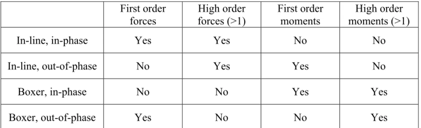
A summary of the different forces and moments acting on the engine is presented in table 2. First order forces High order forces (>1) First order moments High order moments (>1)
In-line, in-phase Yes Yes No No
In-line, out-of-phase No Yes Yes No
Boxer, in-phase No No Yes Yes
Boxer, out-of-phase Yes No No Yes
Table 2: Forces and moments in the different configurations of twin-cylinder engine
3.2.3.6. Balance shafts
The force generated by a balance shaft can be expressed in the two main directions (X and Y) under the form:
θ ω2 ⋅cos ⋅ ⋅ = bs bs x r m F (14) θ ω2⋅sin ⋅ ⋅ = bs bs y r m F (15) rbs*mbs = unbalance mass of the balance shaft
3.2.3.7. Calculations of the moments
Depending on the configuration of the engine, it can exist free moments due to a difference between the forces generated by the cylinders or by the balance shafts. These moments are calculated with respect to the middle of the crankshaft. We can separate the resulting moment
• Mx is the yawing moment (see figure 15)
• My is the pitching moment
• Mz is the rolling moment
• Mres is the resulting moment
4 4 3 3 2 1 2 2 y y y y x Z F Z F a F a F M = ⋅ − ⋅ − ⋅ − ⋅ (16) 4 4 3 3 2 1 2 2 x x x x y Z F Z F a F a F M =− ⋅ + ⋅ + ⋅ + ⋅ (17) 4 4 3 3 4 4 3 3 x x y y z Y F Y F X F X F M =− ⋅ − ⋅ + ⋅ + ⋅ (18) 2 2 2 z y x res M M M M = + + (19) • Indices 1 and 2 relate to the two cylinders
• Indices 3 and 4 relate to the two balance shafts • Xi, Yi and Zi are the coordinates of the balance shafts
• a is the distance between the bore center
Figure 15: Definition of the three moments
3.2.3.8. Forces due to the gas pressure
To calculate the force generated by the gas pressure on the piston, we multiply the relative pressure (p) by the area of the piston (equation (20)).
2 , 2⎟⎠ ⎞ ⎜ ⎝ ⎛ ⋅ ⋅ = p b Fxgp π (20) To calculate the torque of the engine, the gas force is added to the inertia force which gives the total force in the cylinder (equation (21)). This force is then multiplied by the effective lever arm (since the crankshaft rotates, the length of the lever arm varies between zero and the length of the crank arm (r)). That gives the instantaneous torque (Ti) generated by one
cylinder (equation (22)). The sum of the torque generated by each cylinder is averaged over 720 degrees to have the brake torque (T) of the engine.
Fx,gp + Fx,inertia = Fx,total (21) Ti = Fx,total * r * sin θ (22) The gases obtained by the fuel combustion create a pressure acting on the cylinder sleeve, on the piston and on the cylinder head (see figure 17). This pressure is modeled by four forces in the two dimensions drawing of the figure 16. It appears clearly that the horizontal forces (Hl
and Hr) are equivalent and opposed (in a real view, since the cylinder is round, there is an
endless number of forces in the horizontal plane nevertheless the resulting force is still null). So the resultant forces on the cylinder sleeve are null and there are no lateral forces due to the gas pressure.
The force acting on the piston is the one that produces the useful torque. The force is transmitted from the piston to the crankshaft through the connecting rod and from the crankshaft to the engine block (Vp/2) through the bearings. The gas pressure creates exactly
the same force on the cylinder head but in the other direction (Vc = - Vp). This force is
transmitted from the cylinder head to the engine block (vc/2) by the cylinder head bolts. And
thus there are no resulting forces because the two forces counteract each other (Vc/2 = -Vp/2).
The forces due to the gas pressure are inner forces; they are only responsible for the torque and for tensile stresses in the engine block [VANOVERSCHELDE 2008]. They do not need
to be balanced.
4.Evaluation and balance of inertia forces
In this section, we first discuss shortly about the equations of the forces in the engine and the approximations that can be made. After that, we simulate two single-cylinder engines (shorter and longer stroke engines) and different arrangements of two-cylinder engine. Then, we give the results of the calculation of forces and moments for the different configurations of engine described previously (the complete set of curves for all longer stroke twin-cylinder configurations are given in the appendix A). The calculation of forces and moments is carried out for an engine rotation speed of 4000 rpm because it is its maximum rotation speed and it gives the maximum inertia forces. For each engine configuration, we are first interested in the resulting forces and moments for the basic crankshaft (well balanced, no rotating forces generated). Then we study the effect of the unbalance mass of the crankshaft and search for an optimal value of this unbalance mass (minimization of the resulting forces or moments). After that, we compare different configurations of balance shafts and different combinations of crankshaft and balance shafts. We also investigate the effect of the gas pressure in the model.
4.1. Approximation of equations
The equation (10) used to determine the value of Fx is a Fourier series with some coefficients
A0, A2, A4, A6… All of them do not have the same importance and some of them can be
neglected. These coefficients are composed of different powers of the stroke to connecting rod ratio λ. The value of λ is 0,32 so it means that λ5 is 0,0033 which is one percent of λ. Therefore we guess that some terms with higher power of λ could be neglected. We determine in this section which terms in λ and which order of forces can be neglected. To this end, we compare, in table 3, the error on the maximum force and the mean value (averaged over one rotation of the crankshaft) of the relative error between the values of Fx with the equations
limited to a given order (first, second or fourth) and the values of Fx with the equations
limited to the sixth order (we assume that the equations limited to the sixth order are already sufficiently accurate) in the case of the shorter stroke single cylinder engine (described in point 4.2).
Approximation Fx,max (N) Error on Fx,max (%) Mean error (%)
First order 7238,0 24,11 % 101,18 %
Second order 9597,9 0,64 % 1,80 %
Fourth order 9535,5 0,02 % 0,04 %
Sixth order 9537,1
Table 3: Maximum forces and related errors for different approximations of the equations
We notice in table 3 that the error committed if we use only the first order of the equation is very important, 24% on the maximum value but also more than 100 % in the mean (the relative error can be huge when the force is close to zero). According to these results, we choose to work with the first, second and fourth orders terms and to neglect the sixth and higher orders terms because with this simplification, the committed error is less than 0,1% (Mean relative error between fourth and sixth order is 0,04 %, and error between sixth order and higher orders are even smaller).
By reviewing literature [BOSCH 2000], we note that some authors neglect the terms of the third and higher powers in λ. So the calculations are made with only the first order terms and the coefficients of the second order limited to λ. We compare the results obtained with this approximation (Fx,max = 9537,1 N) with the results of the complete sixth order equation
(Fx,max = 9537,1 N). The error on the maximum values of Fx is nearly null (less than 0,1%).
This is due to the fact that the coefficients neglected at the second order (1/4*λ3+15/128*λ5) and sixth order (9/128*λ5) are exactly the opposite of the coefficient of the fourth order (-1/4*λ3-24/128*λ5). Then for θ = 0+k*360° (which is the position that give the maximum value of Fx in this configuration), the error is nearly zero but in the mean, the relative error is
3,8 %. Moreover, we make an error of three percents on the values of the second order forces. So if we choose to balance these forces by counterrotative balance shafts, this will result in an error on the values of the unbalance mass of the shafts. Therefore we decide to work with the first, second and fourth orders of the equations (limited to terms in λ, λ3 and λ5).
4.2. Shorter stroke single-cylinder engine
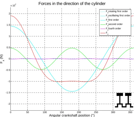
4.2.1. Reference data (case 1)
We are interested first at the most basic engine, one cylinder, with no balance shaft and a well-balanced crankshaft. This means that the crankshaft and the related part of the connecting rod produce no forces. We focus mainly on the forces in the direction of the piston motion (figure 18).
We can see that the forces due to the rotating parts are zero (dotted light blue line), the counterweights are designed to balance the crankshaft and the connecting rod. Then we note that the dominating force is the first order reciprocating force (dashed light blue line) because the movement of the piston is not balanced (maximum value is 7238,1 N). These two forces are first order and their sum is the total first order force in the X-direction (solid light blue line), since the rotating effect is zero, the total first order force is limited to the oscillating component.
Another force with a less important effect but not negligible (maximum value is 2360 N which is 33% of first order maximum value) is the second order force (green line); we can notice that the frequency of the second order effect is, obviously, the double of the first order force.
The force of the fourth order is also represented (magenta line) but it is close to zero (maximum is 31,3 N) and it could be neglected in first approximation.
The red line is the total force in the X-direction (Fx) and it corresponds to the sum of all forces
described previously. We can see that for θ = 0° (TDC), first order and second order forces have the same direction and their effects add to each other to reach the maximum value of Fx
which is 9535,5 N. But for θ = 180° (BDC), first order forces are negative whereas the second order forces are positive so the second order forces reduce the peak value (the maximum negative force is 5077,5 N at θ = 142° & 218°). So the total force in X-direction is smaller at the bottom dead center than at the top dead center.
0 50 100 150 200 250 300 350 -1 -0.8 -0.6 -0.4 -0.2 0 0.2 0.4 0.6 0.8 1
x 104 Forces in the direction of the cylinder
Angular crankshaft position (°)
F x
(N
)
F
xrotating first order
F
xoscillating first order
F xfirst order F xsecond order F xfourth order F x
Figure 18: Fx for shorter stroke single-cylinder engine rotating at 4000 rpm
In figure 19, we notice that the force in the Y-direction (Fy) is, as expected, equal to zero.
Concerning the moments deriving from the forces, they are all null (figure 20). This is a consequence of the fact that the forces of the cylinder are applied at the center of the engine.
0 50 100 150 200 250 300 350 -1 -0.8 -0.6 -0.4 -0.2 0 0.2 0.4 0.6 0.8 1
x 104 Resulting forces in the principal directions
Angular crankshaft position (°)
Fo rc e s ( N ) F x F y
Figure 19: Fx and Fy for shorter stroke single-cylinder engine rotating at 4000 rpm
0 50 100 150 200 250 300 350 -1 -0.8 -0.6 -0.4 -0.2 0 0.2 0.4 0.6 0.8 1
Resulting moments in the principal directions
Angular crankshaft position (°)
Mo me n ts ( Nm) M x M y M z
Then, we calculate the resulting force ( 2 2
y x
res F F
F = + , see figure 21). Since Fy is zero, the
resulting force is equal to the absolute value of Fx.
The resulting moment is obviously equal to zero because all moments are zero.
0 50 100 150 200 250 300 350 0 2000 4000 6000 8000 10000
Amplitude of resulting force
Angular crankshaft position (°)
R e s u lt ing f o rc e (N )
Figure 21: Amplitude of the resulting force for shorter stroke single-cylinder engine rotating at 4000 rpm
Fx,max (N) 9535,49 Fy,max (N) 0,00 Fres,max (N) 9535,49 ΔFres (N) 4719,74 Mx,max (Nm) 0,00 My,max (Nm) 0,00 Mz,max (Nm) 0,00 Mres,max (Nm) 0,00 ΔMres (Nm) 0,00
Table 4 presents a summary of the maximum values obtained for the principal forces and moments. ΔFres and ΔMres are the variations between the maximum and minimum value of
Fres or Mres.
The single-cylinder engine is characterized by important forces (9535 N) of first, second and higher orders. In this case, the force is in pure X-direction; there is no effect in Y-direction due to the balancing of the crankshaft. One major advantage of this engine is that there is no resulting moments in any direction.
4.2.2. Optimization of the crankshaft (case 2)
The previous section shows that one disadvantage of the single-cylinder engine is the important forces (exclusively in X-direction) that are not balanced. We try here to reduce these forces by a proper choice of the crankshaft counterweights. We are aware that modifying the unbalance mass of the crank will increase the forces in the Y-direction; so to avoid increasing the total forces, we search the value of the unbalance mass of the crankshaft that minimizes the maximum resulting force (Fres). This is carried out by making a parametric
study of the unbalance mass with respect to the resulting force (figure 22). The red point indicates the reference value of the crankshaft. This means that an optimal choice of counterweight can nearly divides by two the maximum resulting force.
-0.10 -0.09 -0.08 -0.07 -0.06 -0.05 -0.04 -0.03 -0.02 -0.01 0 2000 4000 6000 8000 10000 12000 14000 16000
Resulting force(unbalanced mass of the crank)
unbalanced mass of the crank
F re s Basic balanced crankshaft Optimized crankshaft
Figure 22: Minimization of Fres in the shorter stroke single-cylinder engine by variation of the unbalance mass of the crank
instead of 0,02054 kg*m). There is no need to calculate the moments because they are still equal to zero. The rotating force of the crankshaft has no influence on them.
Figure 23 shows that, compared to figure 18, the oscillating first order, the second order and fourth order forces are not modified. Only the rotating first order forces (dotted light blue line) have been modified and therefore the total first order force and total force in the X-direction. We notice that the maximum value of the oscillating force is a little higher than the maximum value of the rotating force but with a phase shift of 180° (principle of the counterweight). So the first order forces are reduce from 7238,1 N to 2838,9 N which is a decrease of 61%. When considering also the high order forces, one notices that the maximum value of the total force decreases from 9535,5 N to 5136,2 N, which is a decrease of 46% and the maximum negative value also decrease in the same proportion.
0 50 100 150 200 250 300 350 -8000 -6000 -4000 -2000 0 2000 4000 6000 8000
Forces in the direction of the cylinder
Angular crankshaft position (°)
F x
(N
)
F
xrotating first order
F
xoscillating first order
F xfirst order F xsecond order F xfourth order F x
Figure 23: Fx for optimized shorter stroke single-cylinder engine
Figure 24 shows the total force in the X-direction, as in figure 19, but this time there is also a force in the direction which is the opposite of a sinusoid. The maximum value of the Y-force is a little smaller that the X-Y-force.
One notices, in figure 25, that the maximum value of the resulting force is not reached for only one position of the crankshaft as before but now in three positions. The first maximum is at the TDC as before and the force is in the X-direction. But there are two others maxima at 90° and 270°, these maxima are produced by the Y-forces and the second order X-forces. Table 5 presents a summary of the key results.
0 50 100 150 200 250 300 350 -6000 -4000 -2000 0 2000 4000 6000
Resulting forces in the principal directions
Angular crankshaft position (°)
F o rc es (N ) F x F y
Figure 24: Fx and Fy for optimized shorter stroke single-cylinder engine
0 50 100 150 200 250 300 350 0 1000 2000 3000 4000 5000 6000
Amplitude of resulting force
Angular crankshaft position (°)
R e s u lt ing f o rc e (N )
Fx,max (N) 5136,24 Fy,max (N) 4399,25 Fres,max (N) 5136,29 ΔFres (N) 4595,02 Mx,max (Nm) 0,00 My,max (Nm) 0,00 Mz,max (Nm) 0,00 Mres,max (Nm) 0,00 ΔMres (Nm) 0,00
Table 5: Maximum values of forces and moments for optimized shorter stroke single-cylinder engine
If we compare the results of table 4 and 5, we can conclude that we have achieved rather high reduction by simply modifying the counterweight of the crankshaft. Indeed, we have decreased the X-force at the price of an increasing of the Y-force. Nevertheless, the maximum of Fx and Fy are out of phase, thus the maximum of the resulting force is reduced by 46% and
the variations of resulting force are also smaller.
Optimizing the counterweight of the crankshaft is a non-expensive solution to reduce vibrations and loads on engine supports.
4.2.3. Balance shafts
In this section, we compare different associations of balance shafts and crankshaft for the single-cylinder engine. We begin by adding one or two balance shafts to the engine to counteract first order forces, and then we do the same to counteract second order forces. In the case where we use only one first order balance shaft, the counterweights of the balance shaft are modified to play the role of a second balance shaft.
The position of the balance shafts is really important, especially if we use only one balance shaft. If the balance shafts are not well placed, they will produce forces that are not aligned with the piston and crankshaft forces and it will generate free moments. We choose to place the balance shafts in the same horizontal plane than the crankshaft at 100 mm (arbitrary choice) on each side of the cylinder plane (see figure 26). The balance shafts have to be placed symmetrically with respect to the cylinder row in order to produce no rolling moment. Lengthways, they are positioned at the middle of the engine to avoid free pitching or yawing moments.
Figure 26: Position of the balance shafts in the shorter stroke single-cylinder engine
4.2.3.1. Basic crankshaft + two first order balance shafts (case 3)
We use in this configuration two balance shafts revolving at 4000 rpm to balance first order X-forces. The maximum X-force generated by the two balance shafts has to compensate the maximum first order X-force generated by the oscillating parts of the cylinder (the rotating parts are already balanced and do not produce forces).
• Maximum force generated by the two balance shafts: Fx =2⋅rbs ⋅mbs⋅ω2 (23) • Maximum first order force generated by the cylinders: Fx =r⋅ω2⋅mo (24)
The equality between the equations (23) and (24) gives the equation (25) to calculate the unbalance mass of one balance shaft:
2 0 m r m rbs ⋅ bs = ⋅ (25) Finally, the value of the unbalance mass of one first order balance shaft is 0,020625 kg*m for the position described previously. We notice from this reasoning that the balancing does not depend on the rotation speed.
0 50 100 150 200 250 300 350 -8000 -6000 -4000 -2000 0 2000 4000 6000 8000
Forces in the direction of the cylinder
Angular crankshaft position (°)
F x (N ) F xfirst order F xsecond order F xfourth order F xbalanceshafts F x
Figure 27: Fx for shorter stroke single-cylinder engine with two first order balance shafts
Figure 27 shows that the rotating forces produced by the balance shaft (dark blue line) are exactly the opposite of the engine first order forces (light blue line). The total force (red line) is the sum of the second and fourth order forces which are more or less equivalent to the second order force.
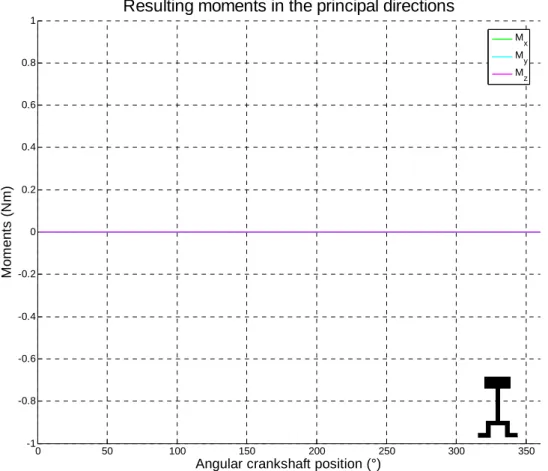
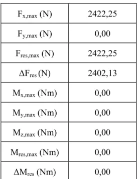
The force in the Y-direction is null so the resulting force is nearly equal to the second order force.
Fx,max (N) 2422,25 Fy,max (N) 0,00 Fres,max (N) 2422,25 ΔFres (N) 2402,13 Mx,max (Nm) 0,00 My,max (Nm) 0,00 Mz,max (Nm) 0,00 Mres,max (Nm) 0,00 ΔMres (Nm) 0,00
Table 6: Maximum value of forces and moments for shorter stroke single-cylinder engine with two first order balance shafts
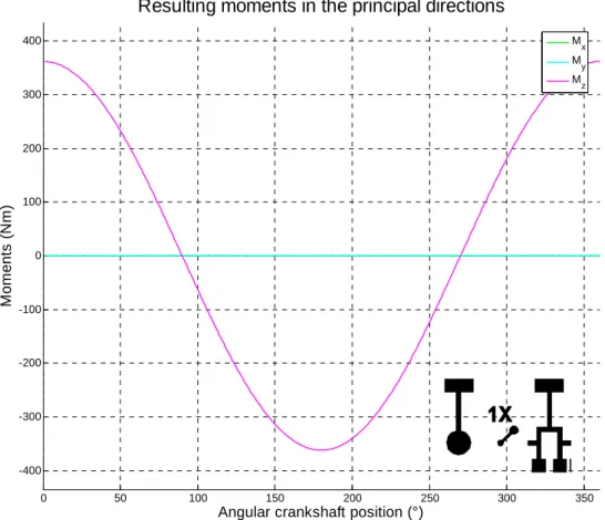
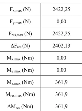
4.2.3.2. Modified crankshaft + one first order balance shaft (case 4)
One alternative to the two first order balance shafts is to incorporate one balance shaft to the crankshaft. The unbalance mass of the balance shaft is added to the unbalance mass of the crank and only the counterrotative balance shaft is kept. By doing this, we use only one balance shaft, which reduces the complexity of the engine.
By comparison with figure 18, the figure 28 shows that the first order forces (light blue line) are reduced by the force of the crankshaft. And the remaining part of the first order is counteracted by the force of the single balance shaft (dark blue line).
The Y-force generated by the crankshaft is counteracted by the Y-force of the balance shaft. Since in this case, the balance shaft has the same X-coordinate than the crankshaft, the Y-force are on the same line, they do not produce any moment around the Z-axis. But the X-forces are not on the same line, so they produce a Z-moment (figure 29).
With only one balance shaft, it is not possible to place it such as the X-forces and the Y-forces are both aligned in the same configuration. So there is always a rolling moment with a single balance shaft. Otherwise, all the results are the same than with two balance shafts (see table 7) with the advantage to have a less complex configuration.
0 50 100 150 200 250 300 350 -8000 -6000 -4000 -2000 0 2000 4000 6000 8000
Forces in the direction of the cylinder
Angular crankshaft position (°)
F x (N ) F xfirst order F xsecond order F xfourth order F xbalanceshafts F x
Figure 28: Fx for shorter stroke single-cylinder engine with one first order balance shaft
0 50 100 150 200 250 300 350 -400 -300 -200 -100 0 100 200 300 400
Resulting moments in the principal directions
Angular crankshaft position (°)
Mo me n ts ( N m) M x M y M z
Fx,max (N) 2422,25 Fy,max (N) 0,00 Fres,max (N) 2422,25 ΔFres (N) 2402,13 Mx,max (Nm) 0,00 My,max (Nm) 0,00 Mz,max (Nm) 361,9 Mres,max (Nm) 361,9 ΔMres (Nm) 361,9
Table 7: Maximum value of forces and moments for shorter stroke single-cylinder engine with one first order balance shaft
4.2.3.3. Optimized crankshaft + two second order balance shafts (case 5) We have seen in figure 23 that when the value of the unbalance mass of the crankshaft is optimized, the second order force become an important part of the resulting force (nearly 50%). So we decide to compensate the entire second order force with two balance shafts rotating at twice the crankshaft speed. Nevertheless, as we reduce the X-force with the balance shafts, we need to calculate a new optimum value for the crankshaft with a parametric study.
• Maximum force generated by the two balance shafts:
2 ) 2 ( 2⋅ ⋅ ⋅ ⋅ω = bs bs x r m F (26) • Maximum second order force generated by the cylinder:
2 2 A m r Fx = ⋅ω ⋅ o⋅ (27)
The equality between the equations (26) and (27) gives the relation (28) to calculate the unbalance mass of one balance shaft:
8 2 0 A m r m rbs ⋅ bs = ⋅ ⋅ (28) Compared to the case with two first order balance shafts, we notice that the unbalance mass of the crank is smaller in this case, 0,04130 kg*m instead of 0,04561 kg*m. And the unbalance mass of one balance shaft is 0,00168 kg*m. This value may seem small, compared to
mind that the balance shafts revolve at twice the crank speed. Since the force is proportional to the square of the rotating speed, when we double the speed, the force is multiplied by four. Figure 30 shows that the force generated by the balance shafts is exactly the opposite of the second order force. So the total X-force is the sum of reduced first order force and negligible fourth order force.
Another advantage of this configuration is that the amplitude (modulus) of the resulting force is nearly constant (see figure 31).
Table 8 presents a summary of the key results.
0 50 100 150 200 250 300 350 -8000 -6000 -4000 -2000 0 2000 4000 6000 8000
Forces in the direction of the cylinder
Angular crankshaft position (°)
F x
(N
)
F
xrotating first order
F
xoscillating first order
F xfirst order F xsecond order F xfourth order F xbalanceshafts F x
0 50 100 150 200 250 300 350 0 500 1000 1500 2000 2500 3000 3500 4000
Amplitude of resulting force
Angular crankshaft position (°)
R e s u lt ing f o rc e (N )
Figure 31: Fres for shorter stroke single-cylinder engine with two second order balance shafts
Fx,max (N) 3657,37 Fy,max (N) 3643,02 Fres,max (N) 3663,17 ΔFres (N) 130,57 Mx,max (Nm) 0,00 My,max (Nm) 0,00 Mz,max (Nm) 0,00 Mres,max (Nm) 0,00 ΔMres (Nm) 0,00
Table 8: Maximum value of forces and moments for shorter stroke single-cylinder engine with two second order balance shafts
4.2.3.4. Modified crankshaft + one first order and one second order balance shaft (case 6)
order force. By comparison with the case without the second order balance shaft, we notice a reduction of 50% of the resulting force but the price is an increase of 25% of the resulting moment (see table 9).
Fx,max (N) 1242,32 Fy,max (N) 1179,93 Fres,max (N) 1242,32 ΔFres (N) 124,77 Mx,max (Nm) 0,00 My,max (Nm) 0 Mz,max (Nm) 479,89 Mres,max (Nm) 479,89 ΔMres (Nm) 479,58
Table 9: Maximum value of forces and moments for shorter stroke single-cylinder engine with one first and one second order balance shafts
4.2.3.5. Three or four balance shafts
We also study some cases with more than two balance shafts. These configurations are more expensive and more difficult to design but they could lead to important reductions in resulting moments and forces.
The first one continues along the former case (case 6) with two second order balance and one first order shafts (the second first order shaft is carried out using a modified balancing of the crankshaft) in order to suppress the entire second order force (case 7).
We are also interested in the case with two first order and one second order balance shafts (case 8).
Finally, the last case consists in two first order and two second order balance shafts, the first and second order forces are completely suppressed in this last case (case 9).
The balance shafts three and four are placed 100mm (arbitrary choice) above the two first balance shafts (see figure 32).
Figure 32: Position of the balance shafts 3 and 4 in the shorter stroke single-cylinder engine
4.2.4. Summary
All the different configurations studied for the shorter stroke single-cylinder engine are summarized in the table (table 10) and graphic (figure 33) below.
Here are a few remarks concerning the results presented in the table:
• The unbalance mass of the first order balance shafts (FOBS) is 0,020625 kg*m. • The unbalance mass of the second order balance shafts (SOBS) is 0,00168 kg*m. • The unbalance mass of the crankshaft is given in the table.
Case 1 2 3 4 5 6 7 8 9
Name Basic crank opti. 2FOBS 1FOBS 2SOBS opti. c. 1FOBS 1SOBS 1FOBS 2SOBS 2FOBS 1SOBS 2FOBS 2SOBS
Crank (kg*m) 0,02054 0,04561 0,02054 0,04116 0,04130 0,04116 0,04116 0,02054 0,02054 Fx,max(N) 9535 5136 2422 2422 3657 1242 63 1243 63 Fy,max(N) 0 4399 0 0 3643 1180 0 1180 0 Fres,max(N) 9535 5136 2422 2422 3663 1242 63 1243 63 ΔFres (N) 4720 4595 2402 2402 131 125 61 125 61 Mx,max(Nm) 0 0 0 0 0 0 0 0 0 My,max(Nm) 0 0 0 0 0 0 0 0 0 Mz,max(Nm) 0 0 0 362 0 480 362 118 0 Mres,max (Nm) 0 0 0 362 0 480 362 118 0 ΔMres(Nm) 0 0 0 362 0 480 362 118 0 Complexity -- - ++ + ++ ++ +++ +++ ++++
Table 10: Maximum values of forces and moments for different balancing systems of the shorter stroke single-cylinder engine rotating at 4000 rpm
0 2500 5000 7500 10000 12500 original data opti. crank
2 fobs 1 fobs 2 sobs 1 fobs 1 sobs 1 fobs 2 sobs 2 fobs 1 sobs 2 fobs 2 sobs F o rces ( N ) 0 220 440 660 880 1100 Mo m e n ts ( N m ) Fres,max Mres,max
Figure 33: Maximum values of resulting forces and moments for different balancing systems of the shorter stroke single-cylinder engine rotating at 4000 rpm
4.3. Longer stroke single-cylinder engine
The engine with the longer stroke is characterized by a higher oscillating mass (0,985 kg > 0,955kg), a longer stroke (0,04775 m > 0,0432 m) and a higher stroke to connecting rod ratio (0,3316 > 0,3176) than the shorter stroke engine. So the forces generated by the longer stroke engine are a little higher than the forces of the shorter stroke engine even if they have the same aspect for the same configuration of engine. Thus, we do not describe once again all results and figures; we only give the final results (table 11) and graphic (figures 34).
Here are a few remarks concerning the results presented in the table:
• The unbalance mass of the first order balance shafts (FOBS) is 0,02352 kg*m. • The unbalance mass of the second order balance shafts (SOBS) is 0,00201 kg*m. • The unbalance mass of the crankshaft is given in the table.
Case 1 2 3 4 5 6 7 8 9
Name Basic crank opti. 2FOBS 1FOBS 2SOBS opti. c. 1FOBS 1SOBS 1FOBS 2SOBS 2FOBS 1SOBS 2FOBS 2SOBS
Crank (kg*m) 0,02001 0,04875 0,02001 0,04353 0,04371 0,04353 0,04353 0,02001 0,02001 Fx,max (N) 10987 5945 2897 2897 4176 1489 82 1489 82 Fy,max (N) 0 5042 0 0 4158 1408 0 1408 0 Fres,max (N) 10987 5945 2897 2897 4184 1489 82 1489 82 ΔFres (N) 10939 5469 2880 2880 171 163 79 163 79 Mx,max (Nm) 0 0 0 0 0 0 0 0 0 My,max (Nm) 0 0 0 0 0 0 0 0 0 Mz,max (Nm) 0 0 0 413 0 554 413 141 0 Mres,max (Nm) 0 0 0 413 0 554 413 141 0 ΔMres (Nm) 0 0 0 413 0 550 413 141 0 Complexity -- - ++ + ++ ++ +++ +++ ++++
Table 11: Maximum values of forces and moments for different balancing systems of the longer stroke single-cylinder engine rotating at 4000 rpm
0 2500 5000 7500 10000 12500 original data opti. crank
2 fobs 1 fobs 2 sobs 1 fobs 1 sobs 1 fobs 2 sobs 2 fobs 1 sobs 2 fobs 2 sobs F o rces ( N ) 0 220 440 660 880 1100 Mo m e n ts ( N m ) Fres,max Mres,max
Figure 34: Maximum values of resulting forces for different balancing systems of the longer stroke single-cylinder engine rotating at 4000 rpm
4.4. Shorter stroke twcylinder line engine,
in-phase arrangement
We focus now on the twin-cylinder engine and we begin with the shorter stroke in-line engine with in-phase arrangement of the crankshaft. As noticed in a first analysis, we expect to note that the forces generated by the complete engine are the double of the forces generated by the single-cylinder engine. So it means that forces of all orders (first, second, fourth…) are not null. And as the pistons move in phase and in the same direction, there is no moment generated.
4.4.1. Reference data (case 1)
We look at the basic configuration of the engine, with no balance shaft and a well-balanced crankshaft. This means that the crankshaft and the related part of the connecting rod produce no forces. We focus mainly on the forces in the direction of the piston motion (figure 35). We notice that the shapes of the forces curves are exactly the same than the curves of the single-cylinder engine (see figure 18). But the values are doubled, the maximum value of the force Fx is 19071 N instead of 9535,5 N for the single-cylinder engine.
0 50 100 150 200 250 300 350 -2 -1.5 -1 -0.5 0 0.5 1 1.5 2
x 104 Forces in the direction of the cylinder
Angular crankshaft position (°)
F x
(N
)
F
xrotating first order
F
xoscillating first order
F xfirst order F xsecond order F xfourth order F x