is an open access repository that collects the work of Arts et Métiers Institute of Technology researchers and makes it freely available over the web where possible.
This is an author-deposited version published in: https://sam.ensam.eu Handle ID: .http://hdl.handle.net/10985/17983
To cite this version :
Laurene LENOIR, Frédéric SEGONDS, Peyre Kim-Anh NGUYEN, Pablo BARTOLUCCI - A methodology to develop a vascular geometry for in vitro cell culture using additive manufacturing -International Journal of Bioprinting - Vol. 5, n°2, p.238 - 2019
99
A methodology to develop a vascular geometry for
in vitro cell culture using additive manufacturing
Laurène Lenoir
1, Frédéric Segonds
1*, Kim-Anh Nguyen
2,3, Pablo Bartolucci
2,41Product Design and Innovation Laboratory (LCPI), Arts et Métiers ParisTech, Paris, 151 Boulevard de l’Hôpital, 75013, France
2EFS UITC, Center Felix Reyes, Research team 2, Créteil, 5 rue Gustave Eiffel, 94017, France 3Imagine Institute, Paris, 24 Boulevard du Montparnasse, 75015, France
4Sickle Cell Referent, Créteil, Center Mondor Hospital, 94017, France
Abstract: Today, additive manufacturing (AM) is implemented in medical industry and profoundly revolutionizes this area. This approach consists of producing parts by additions of layers of successive materials and offers advantages in terms of rapidity, complexity of parts, competitive costs that can be exploited and can lead to a significant advancement in biological research. Everything becomes technically feasible and gives way to a “techno-centered” approach. Many parameters must be controlled in this field, so it is necessary to be guided for the development of such a product. This article aims to present a state of the art of existing design methodologies focused on AM to create medical devices. Finally, a development method is proposed that consists of producing vascular geometry using AM, based on patient data, designed for cell culture in vitro studies.
Keywords: Innovation; Design; Additive manufacturing; Biology; Medical device
*Correspondence to: Frédéric Segonds, Product Design and Innovation Laboratory (LCPI), Arts et Métiers ParisTech, Paris, 151 Boulevard de l’Hôpital, 75013, France; [email protected]
1. Introduction
In recent years, additive manufacturing (AM) offers significant benefits for a wide range of applications, especially in the medical sector. Among these applications, bioprinting has emerged, covering printing of biological cells as well as printing of materials (e.g. polymer, ceramic or even metal) that are used for cellular culture. Thus, AM can be used to create vascular geometries, designed for
in vitro studies. This approach allows to better understand
the physiopathology of many diseases such as sickle cell disease (SCD), the most common severe monogenic disorders in the world with 275,000 cases detected each year in newborns[1,2].
It is due to a mutation in the hemoglobin (Hb) beta-globin gene leading to the production of abnormal HbS. The change in molecular structure allows HbS in
the deoxygenated state to form polymers that promote Hb polymerization, red blood cell (RBC) membrane damage, decreased RBC deformability, intravascular, and extravascular hemolysis. These RBC abnormalities lead to vessel inflammation, vaso-occlusion, and ultimately organ injury[3].
About 114,000 SCD patients die every year from complications[4]. Among them, cerebral vasculopathy
is responsible for stroke all lifelong. However, the physiopathology of cerebral vasculopathy in SCD remains misunderstood. Today, blood exchange transfusions are prescribed for SCD patients with high risk, but this conventional treatment has suspensive effects. Bone marrow transplants offer the only potential cure for SCD but are limited by the number of compatible donors (potential human leukocyte antigen-matched hematopoietic stem cells)[5]. In the future, gene therapy
A methodology to develop a vascular geometry for in vitro cell culture using additive manufacturing © 2019 Frederic S, et al. This is an Open Access article distributed under the terms of the Creative Commons Attribution-NonCommercial 4.0 International License (http://creativecommons.org/licenses/ by-nc/4.0/), permitting all non-commercial use, distribution, and reproduction in any medium, provided the original work is properly cited.
will offer a new approach to cure SCD. The long-term goal of this research is to better understand the pathophysiology of cerebral arterial disease in SCD and possibly to discover or predict the chances of success, of new therapeutic approaches. Unfortunately, animal models do not allow the analysis of the pathophysiology of cerebral vasculopathy because of the huge difference between animal and human according to the vessel geometry and the hemorheological parameters.
Moreover, in vitro 3D models can allow the analysis of extreme conditions that can occur in pathophysiological conditions but are difficult to reproduce except in vitro conditions. A first step is to develop cell culture on a AM vascular geometry for in vitro studies. Actually, there are very few methodologies intended to help the designer to manufacture a vascular geometry in AM and to perform
in vitro cell culture on it. As the product is innovative
and highly multidisciplinary, it is mandatory to answer the following research question: Which methodology should be used to develop an AM vascular geometry designed for cell culture in these in vitro models? This paper presents the design approach used to develop this experimental product. More generally, this method could be applied to all human-based products designed for biological purposes using AM. Finally, a use-case is proposed to validate the method.
2. Research Objectives and Specifications
In the first part of the project, the aim is to decipher the biological pathways involved in the vessel damage due to hemorheological pathological conditions found in SCD children. Previous work provided shear stress abnormalities in the in silico study that should be reproduced and analyzed in a 3D model. Thanks to AM, the prototype of a vascular geometry can be rapidly realized. Then, the effect of sheer stress in a child with SCD will be understood. The constraints established by the various stakeholders involved in this project are as follows: The material must allow to study in vitro the interactions between the blood and the endothelium but also the impact of pathological speeds of the blood flow on the endothelial cells.
3. State-of-The-Art
3.1. Methodologies to Develop Innovative
Medical Devices
Design of innovative complex products in the medical field often involves both engineers and medical experts. As innovative medical devices require collaboration between multidisciplinary teams, it is important to set up a framework to transfer knowledge an efficient between those two domains[6]. Arntzen-Bechina and Leguy proposed
several tools or activities to exchange knowledge, such as literature reviews, informal meetings and discussions with managers, engineers, researchers, and physicians, punctual observations of work practices, and knowledge transfer processes[7]. Wong et al. proposed to follow a
process to manage the engineering and production of biomedical devices. The product development strategy includes a product conceptualization, a market survey and the establishment of strategic alliances, the design, prototyping, and product development, the testing and commissioning, and technology protection, through patents[8].
Bradbury et al. provided an innovative method for rapid design, manufacture, and selection of biomedical devices such as implants or oral dosage pills using electronic data and modeling transmissions through computer networks such as the internet, intranets or extranets[9].
A multi-dimensional digital model may be created based on radiological data and patient information. A collaboration between clinical professionals and engineers allows modification of the digital model. Once the digital model is approved, it may be converted into machine instructions to build the biomedical device. This method for rapid construction of biomedical devices may be applied to AM. Thus, it is necessary first of all to analyze the medical need. Then, the knowledge between the medical profession and the engineers is shared throughout the project.
3.2. Methodologies to Design Innovative
Products based on AM
According to Chu et al., the main role of AM technologies is to produce “parts and devices that are geometrically complex, have graded material compositions, and can be customized.” Besides, it is possible to build almost any shape with a large range of materials, which could be difficult to produce using conventional manufacturing methods such as milling, turning, or casting. AM also offers fabrication of parts with reduced costs and with rapid availability[10].
Bourell et al. advocated to develop new design methodologies dedicated to AM: Design for AM (DFAM)[11]. The most widespread definition of DFAM is
a methodology which “maximize product performance through the synthesis of shapes, sizes, hierarchical structures, and material compositions, subject to the capabilities of AM technologies” and “to best utilize manufacturing process capabilities to achieve desired performance and other life-cycle objectives”[12,13].
Wong and Hernandez presented the general process of AM[14]. It is also presented by Noorani in Figure 1.
It summarizes the stages of product development using rapid prototyping and shows that there can be several iterations before the final product.
Lenoir L, et al.
International Journal of Bioprinting (2019)–Volume 5, Issue 2 101 Chu et al. (2008) proposed a method for DFAM, specialized
in cellular materials, presented in Figure 2. Usually, the microstructure of the part is analyzed and examined after processing it, to determine its mechanical properties. Here, as the material is more complex, the approach consists of reversing the process by “specifying desired behavior.
After planning a manufacturing process, the idea is that the process will be simulated on the current design to determine the as-manufactured shapes, sizes, mesostructures, and microstructures. Then manufactured model will be analyzed to determine whether or not it actually meets design objectives.”
In a multidisciplinary environment, combining engineers and health professionals for instance, not only the process to produce pieces using AM is important but also the way that information, data, and documents are shared and managed.
As Ponche et al. resumed in a study, the “partial approach” in DFAM consists in starting from an initial geometry in a computer-aided design (CAD) model[16].
In general, this geometry is not really designed for an AM process: It will be necessary to modify and improve it for rapid prototyping. The partial approach thus can be used in the case someone has an initial CAD model and wants to manufacture it by AM.
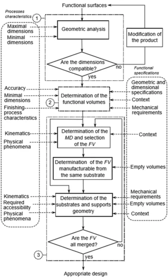
The methodology proposed in this study is presented in Figure 3. It is divided into three main steps. The first step is a global analysis which allows the delimitation of the design problem in terms of geometrical dimensions in relation to the dimensional characteristics of the AM process. The second step allows the fulfillment of the dimensional and geometrical specifications in relation to the AM process capability and the finishing process characteristics. Finally, the third step allows the fulfillment of the physical and assembly requirements in relation to the capability of the AM process.
In general, a rapid prototyping methodology is composed of four phases: Initialization, Design, Development/Manufacturing, and Validation. In addition, the specifications are defined at the flow rate, as are the
Figure 1. Product development cycle adapted from Noorani[15].
Lenoir L, et al.
International Journal of Bioprinting (2019)–Volume 5, Issue 2 103 manufacturing plan and the strategic choices. Finally, the
different methodologies propose a product improvement phase.
3.3. Manufacturing Process of Devices for
Biological Application
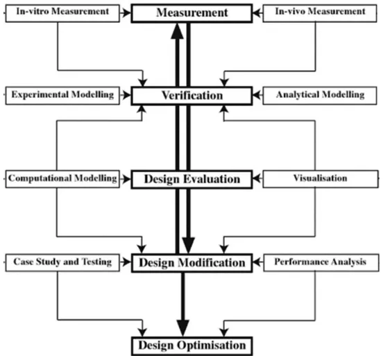
Only methodologies to design and manufacture a product for biological application based on an initial patient medical imaging exist. Wong et al. suggested a framework in five steps (Figure 4): Measurement, verification, design evaluation, design modification, and finally, design optimization[8]. The first phase is
based on both in vivo and in vitro measurement to define the geometry. Verification is needed by modeling the geometry and experimental conditions. Then, the design will be evaluated and analyzed: Surfaces of the previous medical imaging are rebuilt thanks to a CAD model, and flow visualization is generated using different software tools. The model can be modified after a clinical testing phase that requires medical knowledge. Finally, an optimization may start once the product is approved.
Today, polydimethylsiloxane (PDMS) and Flexdym are privileged material for cell-culture devices[17,18].
Concerning microfluidic devices, Shin et al., reported the development of a methodology to create an endothelialized network with a vascular geometry in a biocompatible polymer, PDMS[19].
Using photolithography, master molds were fabricated by etching the network pattern into silicon wafers. Closed channels were created from silicon master molds by replica molding of PDMS and subsequent plasma-bonding of a patterned PDMS template to a flat PDMS sheet.
Usually, laboratories’ chips made of PDMS are relatively simple shapes, which can be manufactured by stereolithography or equivalents.
However, these techniques are not adapted to produce complex geometries. With the recent advances in AM, use of PDMS for the fabrication of such complex shapes has gained considerable interest.
The results of Ozbolat et al. demonstrated that 3D printing of PDMS elastomers is possible and improves the mechanical properties of fabricated samples up to three-fold compared to that of cast ones. It also facilitates the adhesion and the growing[20].
The PDMS is very appreciated for its qualities of translucent and rigidity. However, it has many flaws that
prevent it from being marketable on a large scale. However, the disadvantages of PDMS are the absorption of small molecules, the manufacturing method incompatible with mass production and also its reversible hydrophilicity.
Lachaux et al. found a new polymer (Flexdym) offering flexibility and translucent comparable to PDMS. Flexdym is a copolymer block solution, composed of Di or Triblock according to the different grade. It is similarities with the PDMS but without the drawbacks. Easy and inexpensive microstructuration method, microfluidic devices are fabricated in less than a minute[21].
Furthermore, microfabrication can be performed using a hot-embossing machine or a very simple press equipment; downstream Flexdym is amenable for rapid manufacturing technology such as injection molding. Flexdym can be bonded easily without surface treatments and pressure loads, thanks to is mechanical properties.
Sealing can be achieved either on a simple hot plate or even at room temperature. It is flexible and thus allows cutting into small pieces. It is translucent and biocompatible which will allow the study of cell culture. Due to its bonding qualities, two-part molding is envisaged.
Recently, cell culture studies have been released on VeroClear, AM material. Lu et al. used Veroclear because of its good formation properties and high precision. However, the interactions between cells and materials are affected by topography and surface chemistry of the implant materials, such as roughness and hydrophilic properties[22].
In this study, authors have developed a method of coating waterborne polyurethane (WPU) onto the Veroclear resin to improve the biocompatibility. WPU (Safe polymeric material) is a coating material for creating barriers between corrosive environments and material surfaces. WPU has been used in medical implants because of its low toxicity, good biocompatibility, and coating characteristics.
3.4. Synthesis
Only a few papers rely on AM to produce biomedical parts. This paper highlights existing methodologies for designing innovative products based on AM, others that can help develop innovative medical devices. However, it is difficult to find a methodology that combines these two aspects; there are only a few at the intersection of these two technologies.
The interesting points of these different methodologies are:
• Well understand the goals and needs of the user • Engineers and health professionals pool their
knowledge throughout the project
• Strategic choice and plan of manufacturing before prototyping
• Design by performing user tests
• Optimization of the product with iterations • Final validation
• Make sure the product is correctly used
• Tests prototype and medical return to improve the model.
Thus, in this article, an innovative methodology to achieve a complex vascular geometry using AM is proposed. As mentioned before, there are few methodologies that combine the realization of medical devices and AM processes. Existing methodologies do not propose to simplify the complex geometry to allow faster validation of all subsequent steps such as the choice of material or the cellular study. Here, we can proceed with iteration loops and improve our design each time to finally fulfill the complex form. Thus, the proposed method can be adapted to any case study.
4. A Methodology to Develop Vascular
Geometry for In Vitro Cell Culture using
AM: AM-Biopart
The proposed method (Figure 5) is based on important points told in the synthesis that chosen from the existing methods seen previously.
The method proposed by Lenoir et al. (2019) is divided into four steps. The first “Initialization” consists of understanding and summarizing the objectives, needs, and constraints desired by the medical profession. Knowledge is capitalized and well transferred between engineers and health professionals.
Then, Step II, “concept and feasibility” allow to search and define the different manufacturing methods and then to know their costs.
For Step III, “design and development” is more complex. Geometry simplification strategy is included (Step III, 1) to allow engineers to focus first on the material to be used that meets the different constraints.
Once these parameters have been approved (Step III, 8), the geometry can be made more complex (Step III, 9). Then, the whole process can start again (Steps III, 2) to (Steps III, 7), through an improvement of the design, until the final validation of the realistic 3D model.
Finally, during the last step, the design is optimized by performing user tests. At the end, once everything is validated and optimized, only training for clinical use remains.
5. Use Case AM-Biopart Adapted to the
Manufacturing of a Carotid
In this section, the method is tested on the manufacturing of a carotid (Figure 6) in vitro to understand the physiopathology.
This carotid was modeled by ARM (Figure 7), on a sickle cell child. ARM is an exam that specifically
Lenoir L, et al.
International Journal of Bioprinting (2019)–Volume 5, Issue 2 105 addresses the body’s vessels, arteries, and veins, often
better visualized after injection, of a product[25].
The focus is made on Step III “design and development”: 1. Idea of simplified geometry
The carotid geometry have a very complex form that is why it bring back to a simplified form. The complex geometry is changed in a tube of 50 mm length and 4 mm internal diameter. With each side connectors for the pump (Figure 7).
The simplification of the model has been established by engineers and biological researchers. It consists of bringing the complex model back to a simple shape, here a tube. Thus, this simplified geometry will make it possible to validate as quickly as possible all the elements on the cellular culture part as well as the manufacturing method of the tube. Finally, once everything is approved, a new iteration is performed with more complex geometry.
2. CAD design
Achievements of several CAD with CATIA software (Figure 8) show a half-mold for casting.
3. Criteria related to process and the material
After the CAD, it is necessary to choose the process and the material to use. Here, the molds are made in AM with a material called acrylonitrile butadiene styrene, which is a thermoplastic polymer having good impact strength, relatively rigid, lightweight, and moldable. Then, the PDMS was cast; the result is shown in Figure 9.
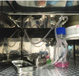
4. In vitro cell-culture testing on prototypes and testing under flow conditions
PDMS has been tested in cell culture and inflow conditions, using a pump that can send large flows. During flow cell culture development, the prototype and manufacturing of PDMS tube were ameliorated to optimize la perfusion at high flow and observation on microscopy.
Figure 7. Simplification of the carotid geometry.
Figure 8. Half-mold for casting.
Figure 6. Branches of the internal carotid artery (A) lateral view
(B) anteroposterior view (PEACE 2017)[24].
A B
5. Observation and biologist Feedback
Human umbilical vein endothelial cells (HUVECs) were seeded in a tube fabricated by two-half mold technique. After 2 h of static culture, a homogenous
monolayer with confluence was observed (Figure 10). A weak flow rate perfusion (Figure 11, shear stress 1 dyn/cm²) was then applicated on cells for 3H following by immunostaining to visualize specific markers of endothelial cells (PECAM-1, Platelet endothelial cell adhesion molecule 1) and their nuclear (DAPI). The results demonstrated that HUVECs monolayer was still confluence (Figure 12).
As flow experiments in artificial carotid will be performed at high shear stress, HUVECs monolayer was challenged with flow culture at high flow rate perfusion (shear stress 6.5 dyn/cm²). However, the assay was stopped after 12 min because of medium leaking at bonding site on the two-half tube. Moreover, on phase-contrast microscopy, cells detachments were found in many areas (Figure 13).
Figure 9. Polydimethylsiloxane cast in two parts in mold
printed in 3D.
Figure 11. Experimental of blood flow in a polydimethylsiloxane
molded carotid (100 mL/min).
Figure 10. Human umbilical vein endothelial cells after 2 h of
static culture.
Figure 12. Human umbilical vein endothelial cells (HUVECs)
culture with weak flow rate perfusion. Immunostaining of platelet endothelial cell adhesion molecule-(green, a membrane specific marker of HUVECs) and nuclei (DAPI, blue).
Figure 13. Human umbilical vein endothelial cells culture with
Lenoir L, et al.
International Journal of Bioprinting (2019)–Volume 5, Issue 2 107 Therefore, to reach the objective of flow experiment
in carotid, molding technique, and cells resistance under high shear stress must be improved.
6. Conclusion and Future Work
In this paper, a global framework of design approach focused on AM to develop vascular geometry is proposed. It can be applied to all human-based products designed for biological purposes using AM. The main research question of this article is: Which methodology should be used to develop an AM vascular geometry designed for cell culture in these in vitro models?
The proposed AM-Biopart methodology takes place in four stages with initialization, concept and feasibility, design and development, and finally validation and optimization. This allows us to have a common thread for people wishing to achieve vascular geometry in AM, with the collaboration of different trades. The proposed method has been successfully applied to the design of a carotid artery. However, for later if we want to guarantee a fully optimized part, some process parameters, such as the choice of laser power, scanning speed, and hatch spacing, must be taken into account in the process. Future work will involve testing the proposed methodology on a more complex case study.
Conflicts of Interest
No potential conflicts of interest were reported by the authors.
Authors’ Contributions
Laurène Lenoir is an engineering student at Arts et
Metiers Paristech School of Engineering in Paris, France and in a double degree of master research Innovation and Design at Product Design and Innovation Laboratory (LCPI).
Frédéric Segonds is Associate Professor of Mechanical
Engineering at Arts et Metiers ParisTech School of Engineering in Paris, France, and member of the Product Design and Innovation Laboratory (LCPI). His research interests focus on product lifecycle management, early stages of design collaboration optimization and Creativity and Design With/For Additive Manufacturing (DWAM/DFAM).
Pablo Bartolucci, MD, PhD is full Professor in
medicine at French Sickle Cell Referent Center – Henri Mondor hospital, and leader of research group (Mondor Institute Biomedical research, INSERM U955 IMRB-team 2)
Kim-Anh Nguyen MD, PhD is a researcher at Imagine
Institute and French Blood Establishment, Mondor Institute Biomedical research, INSERM U955-team 2.
References
1. Lorec A, 2017, Un Vecteur Made in CEA Contre la
Drépanocytose. Les Défis Du Cea, 24(213):8-9.
2. Rees DC, Williams TN, Gladwin MT, 2010,
Sickle-cell Disease. Lancet, 376(9757):2018-31. DOI 10.1016/ S0140-6736(10)61029-X.
3. Roseff SD, 2009, Sickle Cell Disease: A Review.
Immunohematol J Blood Group Serol Educ, 25(2):67-74.
4. GBD, 2015, Mortality and Causes of Death Collaborators 2016,
Global, Regional, and National Life Expectancy, All-cause Mortality, and Cause-specific Mortality for 249 Causes of Death, 1980-2015: A Systematic Analysis for the Global Burden of Disease Study 2015. Lancet, 388(10053):1459-544. DOI 10.1016/S0140-6736(16)31012-1.
5. National Heart, Lung and Blood Institute, 2016, How is
Sickle Cell Disease Treated? Amended; 2017. Available from: https://www.nhlbi.nih.gov/health-topics/sickle-cell-disease. [Last accessed on 2019 May 24].
6. Hagedorn TJ, Grosse IR, Krishnamurty S, 2015, A Concept
Ideation Framework for Medical Device Design. J Biomed Inform, 55:218-30. DOI 10.1016/j.jbi.2015.04.010.
7. Arntzen-Bechina A, Leguy C, 2007, A Model of Knowledge
Sharing in Biomedical Engineering: Challenges and Requirements. J Bus Chem, 4(1):27-43.
8. Wong KK, Tu JY, Sun Z, et al., 2013, Methods in Research
and Development of Biomedical Devices. Singapore: World Scientific Publishing Co.
9. Bradbury TJ, Gaylo CM, Fairweather JA, et al., 2004, System
and Method for Rapidly Customizing Design, Manufacture and/or Selection of Biomedical Devices. U.S. Patent Number 6772026.
10. Chu C, Graf G, Rosen DW, 2008, Design for Additive Manufacturing of Cellular Structures. Comput Aided Des Appl, 5(5):686-96.
11. Bourell DL, Beaman JB, Leu MC, et al., 2009, A Brief History of Additive Manufacturing and the 2009 Roadmap for Additive Manufacturing: Looking Back and Looking Ahead. In: Proceedings of the US-Turkey Workshop on Rapid Technologies, pp. 24-25.
12. Gibson I, Rosen D, Stucker B, 2015, Additive Manufacturing Technologies: 3D Printing, Rapid Prototyping, and
Direct Digital Manufacturing. New York: Springer.
DOI 10.1007/978-1-4939-2113-3.
13. Rosen DW, 2007, Computer-Aided Design for Additive Manufacturing of Cellular Structures. Comput Aided Des Appl, 4(5):585-94.
14. Wong KV, Hernandez A, 2012, A Review of Additive Manufacturing. ISRN Mech Eng, 2012:1-10.
15. Noorani RI, 2006, Rapid Prototyping: Principles and Applications. Los Angeles: John Wiley and Sons.
16. Ponche R, Hascoet JY, Kerbrat O, et al., 2012, A New Global Approach to Design for Additive Manufacturing. Virtual Phys Prototyp, 7(2):93-105.
17. Mcdonald JC, Duffy DC, Anderson JR, et al., 2000, Fabrication of Microfluidic Systems in Poly (Dimethylsiloxane). Electrophoresis, 21(1):27-40. DOI 10.1002/(sici)1522-2683 (20000101)21:1<27:aid-elps27>3.0.co;2-c.
18. Kaihara S, Borenstein J, Koka R, et al., 2000, Silicon Micromachining to Tissue Engineer Branched Vascular Channels for Liver Fabrication. Tissue Eng, 6:105-17. DOI 10.1089/107632700320739.
19. Shin M, Matsuda K, Ishii O, et al., 2004, Endothelialized Networks with a Vascular Geometry in Microfabricated Poly(Dimethyl Siloxane). Biomed Microdevices, 6:269-78. DOI 10.1023/b: bmmd.0000048559.29932.27.
20. Ozbolat V, Dey M, Ayan B, et al., 2018, 3D Printing of PDMS Improves Its Mechanical and Cell Adhesion Properties. ACS Biomater Sci Eng, 4(2):682-93. DOI 10.1021/ acsbiomaterials.7b00646.
21. Lachaux J, Alcaine C, Gómez-Escoda B, et al., 2017, Thermoplastic Elastomer with Advanced Hydrophilization and Bonding Performances for Rapid (30 s) and Easy Molding of Microfluidic Devices. Lap Chip, 17:2581-94. DOI 10.1039/c7lc00488e.
22. Lu Z, Jiang X, Zuo X, et al., 2016, Improvement of Cytocompatibility of 3D-printing Resins for Endothelial Cell Adhesion. RSC Adv, 6(104):102381-8. DOI 10.1039/c6ra20700f. 23. Lenoir L, Segonds F, Bartolucci P, et al., 2019, A Methodology
to Product a Complex Vascular Geometry Using Mainly Additive Manufacturing. Paris: CONFERE.
24. Peace D, 2017, Chapter 1: Neuro-ophthalmic anatomy. Fastest Otolaryngol Ophthalmol Insight Eng, 1: 1-8. 25. Vignon I, 2018, Carotid Angiography-MRI Model. Inria:
![Figure 2. Design for additive manufacturing system and overall method from Chu et al. [10]](https://thumb-eu.123doks.com/thumbv2/123doknet/7437428.220346/4.893.176.725.841.1066/figure-design-additive-manufacturing-overall-method-chu-et.webp)
![Figure 5. Proposed method additive manufacturing-Biopart by Lenoir et al. [23]](https://thumb-eu.123doks.com/thumbv2/123doknet/7437428.220346/8.893.462.820.662.843/figure-proposed-method-additive-manufacturing-biopart-lenoir-et.webp)