Universit6 de Sherbrooke
3U5b007a07357
^A
,1 ^ f"ST! i
'k d^aAi,^,s-^-SYNTHESIS AND CHARACTERIZATION OF NEW SYSTEMS OF STOE-CHAIN
LIQUID CRYSTALUNE POLYMERS AND ORIENTATION STUDIES
by
Guoxiong Yuan
A thesis submitted in fulfillment of the requirement for the degree of master
of science (M. Sc.) ofDepartement de Chimie
FACULTE DES SCffiNCES
UNIVERSITE DE SHERBROOKE
Sherbrooke, Quebec, Canada, Febmary 1997
1*1
National Library of Canada Acquisitions and Bibliographic Services 395 Wellington Street Ottawa ON K1AON4 Canada Bibliotheque nationale du Canada Acquisitions et sen/ices bibliographiques 395, rue Wellington Ottawa ON K1AON4 CanadaYour file Volre reference Our file Notre ref6rence
The author has granted a
non-exclusive licence allowing the
National Library of Canada to
reproduce, loan, distribute or sell
copies of this thesis iti microform,
paper or electronic formats.
The author retains ownership of the
copyright in this thesis. Neither the
thesis nor substantial extracts from it
may be printed or otherwise
reproduced without the author's
permission.
L'auteur a accorde une licence non
exclusive pennettant a la
Bibliofheque nationale du Canada de
reproduire, prefer, distnbuer ou
vendre des copies de cette these sous
la fonne de microfiche/fihn, de
reproduction sur papier ou sur format
electronique.
L'auteur conserve la propriete du
droit d'auteur qui protege cette these.
Ni la these ni des extraits substantiels
de celle-ci ne doivent etare imprimes
ou autrement reproduits sans son
autonsation.
SOMMAIRE
Les travaux de recherche decrits dans ce memoire comprennent quatre projets separes. Dans Ie premier prqjet, nous avons prepare une serie de reseaux interpenetres composes de deux
polymeres cristaux liquides a chame laterale (PCLCLs). Nous discutons la synthese et la
caracterisation ainsi que Ie potentiel de ce nouveau syst^me cristallin liquide, d6montr6 pour la toute premiere fois, dans la recherche de nouveaux materiaux fonctionnels. Dans Ie deuxieme projet, deux PCLCLs sont greffes sur Styrene-Butadiene-Styrene (SBS), un copolymere a trois blocs, par une polymerisation radicalaire de monomeres mesogenes dans une solution avec Ie SB S dissouts. Nous montrons que les materiaux resultants possedent la caracteristique interessante de se comporter comme un ^lastomere thermoplastique, et qu'une stmcture monodomaine des unites mesogenes peut etre facilement induite par retirement d'un film et puis conservee par un traitement thermique a deux etapes. Cette technique speciale peut etre utilisee pour un grand nombre de PCLCLs, et represente une nouvelle approche pour arriver a un controle de la structure monodomaine. Dans Ie troisieme projet, nous avons etudie Forientation des unites mesogenes induite par 1'efFet mecanique dans deux series de PCLCLs contenant des ions. Nous avons observe que dans un cas, ou Ie groupe mesogene est un biphenyle, les agregats ioniques n'influencent pas 1'orientation atteinte. Par contre, pour les ionomeres dont Ie groupe mesogene est un benzoate de phenyle, 1'orientation maximale decroTt en augmentant la concentration des ions, indiquant que les agregats ioniques reduisent 1'ordre moleculaire a 1'interieur de domaines nematiques. Finalement, dans Ie demier projet, nous avons etudie Ie comportement en relaxation d'orientation d'un PCLCL etire lorsqu'il est chauffe, tout en conservant la deformation du film, pres de ses transitions de phases. Un phenomene de reorientation de groupes mesogenes induit par une transition de phases de nematique - smectique a ete observe pour la premiere fois. Cette reorientation est caracterisee par une rotation de 90° de groupes mesogenes, passant d'une orientation perpendiculaire par
rapport a la direction d'etirement, laquelle est Ie resultat de 1'etirement mecanique, a une orientation parallele. Nous discutons ce phenomene ainsi que d'autres resultats obtenus dans cette etude.
ABSTRACT
The research work described in this thesis consists of four separate projects. In the first project, we have prepared a series of interpenetrating networks based on two covalently cross-linked side-chain liquid crystalline polymers (SCLCPs). We discuss the synthesis and
characterization as well as the potential of this novel liquid crystalline system in the search of
new functional materials. In the second project, two SCLCPs were grafted onto a
styrene-butadiene-styrene (SB S) tri-block copolymer through a radical polymerization of the
mesogenic monomers in a SB S solution. We show that the resulting SCLCP-based materials have the interesting feature to behave like a thermoplastic elastomer, and that a monodomain stmcture of the mesogens can easily be induced by a film stretching and then preserved after a two-step thermal annealing process. This special technique is applicable to a large number of SCLCPs, and represents a new approach for achieving a control the monodomain structure.
In the third project, the mechanically-induced orientation of the mesogens in two groups of
ion-containing SCLCPs was investigated. We found that in the case of a SCLCP carrying
biphenyl mesogenic moieties the ionic aggregates show no influence on the orientation. By contrast, in the case of a SCLCP containing phenyl benzoate units, the achievable orientation decreases as the ion content increases, indicating that the ionic aggregates reduce the order inside nematic domains. In the last project, the orientational relaxation behavior of a stretched
SCLCP was studied by heating the deformed film under strain to temperatures near its phase
transitions. A mesophase-transition-induced reorientation phenomenon was observed for the first time. When the stretched SCLCP undergoes a smectic-nematic transition, the pendent
mesogenic groups, which are initially oriented perpendicularly with respect to the stretching
direction, flip 90° to give rise to a parallel orientation. We discuss this observation and other related phenomena.
ACKNOWLEDGEMENT
Firstly, I wish to thank my thesis' supervisor. Professor Yue Zhao, for his guidance, supervision, advice, support and assistance through my study and all research work pursuing in polymer science during my Master degree's program and in the preparation of this thesis.
Specially, I wish to thank my wife, Yan, for her giving me a continuing support in my study
and research work.
Finally, I wish to acknowledge the Natural Sciences and Engineering Research Council of
Canada and Ie Fonds pour la Formation de Chercheurs et 1'Aide a la Recherche du Quebec for financial support.
TABLE OF CONTENTS
SOMMAIRE ...ii
ABSTRACT ...iv
ACKNOWLEDGEMENT ...v
TABLE OF CONTENTS ...vi
LIST OF TABLES ...be LIST OF FIGURES ...x
ABBREVIATIONS ...xv
mTRODUCTION ...1
CHAPTER 1 - SYNTHESIS AND CHARACTERIZATION OF
INTERPENETRATING LIQUID CRYSTALUNE
POLYMER NETWORKS ...71.1 Background ...7
1.2 Synthesis of H.CPNS ...10
1.2.1 ILCPNs with two covalent networks ...11
1.2.2 ILCPNs involving LC ionomers ...13
1.2.3 Factors which determine the success of the preparation of DXPNs ... 15
1.3 Characterization of ELCPNs ...17
1.3.1 Determination of the compositions ofILCPNs samples ...17
1.3.2 Phase transitions of ILCPNs ...23
1.3.2.1 ILCPNs with two covalent networks ...25
1.3.2.2 ILCPNs involving LC ionomers ...30
CHAPTER 2 - GRAFTING OF LIQUID CRYSTALLINE POLYMERS
ON A STYRENE-BUTADffiNE-STYRENE TRIBLOCK
COPOLYMER AND ORIENTATION INDUCTION ...34
2.1 Introduction ...34
2.2 Preparation of Graft Copolymers ...35
2.2.1 Synthesis procedure ...35
2.2.2 Characterization results ...38
2.2.2.1 Polarizing microscopy ...39
2.2.2.2 Differential scanning calorimetry ...41
2.2.3 Discussion ...44
2.3 Orientation Induction ...46
2.3.1 Orientation characterization through infrared dichroism ...46
2.3.2 Orientation measurements ...49
2.3.2.1 Film preparation ...49
2.3.3.2 Film stretching ...50
2.3.2.3 Orientation measurements ...50
2.3.3 Development of the monodomain structure ...52
2.3.4 Orientation preservation ...55
2.3.5 Discussion ...58
2.4 Conclusion ...58
CHAPTER 3 - STRESS-INDUCED ORIENTATION OF SmE-CHAIN
LIQUID CRYSTALLINE IONOMERS IN BLENDS WITH
POLY(VINYL CHLORIDE) AS MATRIX ...603.1 Background ...60
3.2 Experimental ...61
3.3.2 Orientation behaviors ...65
3.3.2.1 lonomers with biphenyl moieties ...65
3.3.2.2 lonomers with phenyl benzoate moieties ...70
3.4 Conclusion ...80
CHAPTER 4 - MESOPHASE TRANSITION-INDUCED REORIENTATION
IN A STRETCHED SIDE-CHAIN LIQUID
CRYSTALLINEPOLYMER...824.1 Background ...82
4.2 Experimental ...84
4.3 Results and Discussion ...86
4.4 Conclusion ...97
CONCLUSION ...99
LIST OF TABLES
1. Composition of D..CPNS with two covalent networks ...19
2. Composition ofDLCPNs involving LC ionomers ...22
3. Phase transition temperatures and enthalpies of the samples ...24
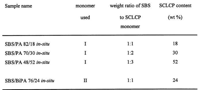
4. SCLCP contents in prepared in-situ samples ...38
LIST OF FIGURES
1. Schematic representation of the components ofSCLCPs ...1
2. Schematic representation of the molecular arrangements in some liquid
crystal phases ...3
3. Schematic representation of a transition from polydomain to a monodomain and induced macroscopic orientation ofmesogenic groups in nematic phase
ofSCLCPs ...4
4. Basic synthesis method for sequential IPNs ...8
5. Schematic representation of the cross-Unking from the ionic aggregates ... 14
6. Infrared spectra ofPolyOCHs, PolyCN and their blend samples:
(1) PolyCN, (2) PolyOCHs/PolyCN, 30/70,
(3) PolyOCHs/PolyCN, 50/50, (4) PolyOCHs/PolyCN, 70/30,
(5) PolyOCHs/PolyCN, 90/10 and (6) PolyOCHs...18
7. Content ofPolyCN in the PolyCN/PolyOCHs blend vs. the absorbance
ratio ofA-cN/A-c=o ...19
8. Infrared spectra ofPolyCN and its ionomers: (1) netCNNa(7.3%),
(2) netCNNa(5.3%), (3) netCNNa(2.5%) and (4) PolyCN ...20
9. Infrared spectra of (1) netCNNa(5.3%), (2) netCNNa(5.3%)-netCN(20%)
and (3) netCN(20%) ...21
10. Linear reference curves of -COO'NaT content as a function of ^0/^2 ... .22
11. DSC heating curves of (1) PolyOCHs, (2) PoIyOCHs/PolyCN 50/50 blend
and (3) PolyCN...^
12. Polarizing optical micrograph of the 50/50 blend ofPolyOCHs and
PolyCN at 80 °C. Magnification: 170x ...26
13. DSC heating curves of (1) netOCHs(20%), (2) netOCH3(20%)-netCN(10%)
and (3) netCN(10%)...^
14. DSC heating curves of (1) netOCH3(20%), (2) netOCH3(20%)-netCN(20%)
and (3) netCN(20%) ...28
15. DSC heating curves of (1) netOCHsClOVo), (2) netOCH3(10%)-netCN(20%)
and (3) netCN(20%) ...29
16. DSC heating curves of (1) netCN(10%), (2) netCN(10%)-netOCH3(20%)
and netOCH3(20%) ...30
17. DSC heating curves of (1) netCNNa(2.5%), (2) netCNNa(2.5%)-netCN(20%),
(3) netCNNa(5.3%), (4) netCNNa(5.3%)-netCN(20%) (5) netCNNa(7.3%),
(6) netCNNa(7.3%)-netCN(20%) and (7) netCN(20%) ...31
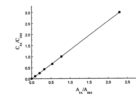
18. The concentration ratio of CPA/CSBS as a function of absorbance
ratio ofApA/AsBs ...37
19. Polarizing photomicrographs for (1) PA, (2) SBS/PA 70/30 blend,
and (3) SBS/PA 70/30 in-situ. Magnification: 410x ...40
20. Polarizing photomicrographs for (1) BiPA, (2) SBS/BiPA 76/24 blend,
and (3) SBS/BiPA 76/24 in-situ. Magnification: 410x ...41
21. DSC heating curves of (1) the SBS/PA 82/18 blend sample
and (2) the SBS/PA 82/18 in-situ sample ...42
22. DSC heating curves of (1) the SBS/PA 70/30 blend sample
and (2) the SBS/PA 70/30 in-situ sample ...43
23. DSC heating curves of (1) the SBS/BiPA 76/24 blend sample
and (2) the SBS/BiPA 76/24 in-situ sample ...44
24. Polarizing photomicrographs for SBS/PA 48/52 in-situ sample at 80 °C,
(1) before, and (2) after the first precipitation in methanol,
Magnification: 410x ...45
25. Linearly polarized IRabsorbance of structural units ...47
27. Definition of axes of the mesogenic group and main chain of PA ... 51
28. The infrared spectra of a SBS/PA in-situ sample exhibited the characteristic
stretching vibration band at 223 0 cm - the cyano end groups (~C=N) ...51
29. Order parameter ?2 vs draw ratio (K) for SBS/PA 82/18 in-situ sample
stretching at room temperature ...53
30. Order parameter ?2 vs draw ratio (^) for SBS/PA 70/30 in-situ sample
stretching at room temperature (A) and at 50 C (•), respectively ... 53
31. Order parameter ?2 vs draw ratio (\) for SBS/BiPA 76/24 in-situ sample
stretching at room temperature (0) and at 5 0 °C (•), respectively ... 54
32. Residual Order parameter ?2 in relaxed film vs film elastic recovery for
SBS/PA 70/30 in-situ after (a) thermal annealing on deformed film
under strain (•), and (b) free film annealing on a relaxed film showing
zero elastic recovery (A) ...56
33. Residual Order parameter Pi in relaxed film vs film elastic recovery for
SBS/BiPA 76/24 in-situ after (a) thermal annealing on deformed film
under strain (•), and (b) free film annealing on a relaxed film showing
zero elastic recovery (A) ...57
34. DSC heating curves of the blends containing 10 wt % of (1) A2, and (2) B2,
showing the phase separation in the blends ...65
35. Order parameter of (a) the mesogenic groups and (b) the PVC matrix versus
draw ratio for the blends containing the polymer and the ionomer samples in
the series A: A1C), A2(0) and A3(A). The blend samples were stretched
at 80°C ...67
36. (a) Order parameter of the mesogenic groups versus stretching temperature, (b) order parameter of the mesogenic groups versus reduced stretching temperature, and (c) order parameter of the PVC matrix versus stretching temperature for the blends containing the polymer and the ionomer samples
to?.=2.5 ...68,69
37. Order parameter of (a) the mesogenic groups and (b) the PVC matrix versus
draw ratio for the blends containing the polymer and the ionomer samples in
the series B: BlC), B2(0), B3(A) and B4(A). The blend samples were
stretched at 100°C ...71
38. (a) Order parameter of the mesogenic groups versus stretching temperature, (b) order parameter of the mesogenic groups versus reduced stretching temperature, and (c) order parameter of the PVC matrix versus stretching temperature for the blends containing the polymer and the ionomer
samples in the series B: BlC), B2(0),B3(A) and B4(A).The blend
samples were stretched to K = 2 ...72, 73
39. Order parameter of the mesogenic groups versus stretching temperature for the blend containing B3, stretched to K = 2. The orientation
measurements were made (1) immediately following stretching with the
sample held at the stretching temperature (•), and (2) after cooling under
strain of the sample to room temperature (0) ...74
40. Order parameter of the mesogenic groups versus temperature for the blend containing B3, stretched to ^ = 2 at 115°C and then allowed to cool under strain (•). The sample was then reheated to 115°C and re-cooled under strain (0). The cooling curve of the oven is shown, indicating
a cooling rate of~0.6°C/min ...76
41. Order parameter of the mesogenic groups versus aging time for the
blend containing B3, stretched to K= 2 at 80°C (•) and 115°C (0),
and held at these temperatures for different lengths of time before
quenching at room temperature ...77
42. Order parameter of the mesogenic groups versus temperature for
The cooling curve is similar to that shown in Figure 40 ...79
43. DSC heating curve and polarizing optical micrographs at (a) 117 °C
and (b) 105 °C for BiPA5. Magnification : 280x ...85
44. Orientation parameter vs annealing time for samples under strain
and annealed at different temperatures as indicated in the figure ...87
45. Orientation parameter vs annealing time for a sample under strain and annealed continuously at different temperatures indicated in the figure. The times at which a temperature change is made are
indicated by the arrows ...90
46. Schematic representation of the irreversible, mesophase transition-induced
reorientation process (a-c) and the reversible orientation recovery (c-d). ...91
47. Orientation parameter vs annealing time for a sample under strain
and annealed alternatively at 115 and 105 C. The times at which
a temperature change is made are indicated by the arrows ...92
48. Orientation parameter vs annealing time for a sample under strain and annealed alternatively at 116 and 105 °C. The times at which
a temperature change is made are indicated by the arrows ...93
49. Schematic representation of the state of alignment of the liquid
ABBREVIATIONS
AcronymMeaning
SCLCPs
LC
LCPs
SCLCEs
ILCPNs
IPNs
SBS
FTIR
DSC
GPC
AIBN
PB
PS
PVC
PMMA
PVA
side-chain liquid crystalline polymers
liquid crystalline
liquid crystalline polymers
side-chain liquid crystalline elastomers
mteq)enetrating liquid crystalline polymer networks interpenetrating polymer networks
styrene-butadiene-styrene Fourier-transform infrared
differential scanning calorimetry
gel permeation chromatography
azobisisobutyronitrile
polybutadiene
polystyrene
poly(vinyl chloride)
poly(methyl methacrylate)
poly(vinyl alcohol)
INTRODUCTION
Side-chain liquid crystalline polymers (SCLCPs) are recognized as attractive functional
materials because of a number of potential applications in various high-tech fields, including
microelectronics, optical data storage, and nonlinear optics (1, 2). Since the first
demonstration of SCLCPs in late Eighties and, in particular, during the last decade, a
considerable amount of research works has been dedicated to the synthesis of new SCLCPs and to the understanding of the ordered structures in these polymers. The purpose of the
present study is to make a contribution to the findings of novel systems based on SCLCPs,
and, when possible, to investigate the induction of the monodomain structure in the materials.
Before describing the contents of the subsequent chapters in this thesis, we will make a brief
introduction to some important concepts in order to set a proper background for our studies.
SCLCPs are generally built up with three basic structural components: polymer backbone,
mesogenic unit, which is the liquid crystal forming component, and flexible spacer, usually a
short aliphatic chain (two to six €N2 units). Unlike main-chain liquid crystalline polymers, in
SCLCPs the rigid, rod-like mesogenic groups are linked to polymer main chain as pendent
groups through the flexible spacer. The basic structure of SCLCPs is shown in Figure 1.
Flexible Spacer
/
-i.
Mesogem'c Unit
Potyfner Backbone
In the liquid crystal phases, these individual components have opposing tendencies. The
polymer chains are entropically driven to a random coil type conformation, while the
mesogenic units stabilize with long range orientational ordering. As individual units, the
polymer chains and the mesogenic units would phase separate. However, the inherent chemical connectivity of the side-chain system inhibits this. As a result, there is a coupling of the behavior of the polymer chain and the mesogenic units. Now, it is known that the key to
making SCLCPs is the incorporation of the flexible spacer between the mesogenic group and
its attachment point to the backbone. With the spacer, the rigid groups can be sufficiently
de-coupled from the perturbing influence of the backbone to pack as a mesophase. However, whatever length of the flexible spacer, coupling effects always exist and their effects may be
strong or weak. This is why the SCLCPs with different length of flexible spacers have
different liquid crystalline (LC) phases.
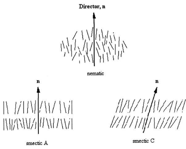
Because of the opposing influences ofentropically disordered polymer chain conformation and the long range orientation ordering of the mesogenic units as mentioned above, SCLCPs exhibit a rich phase behaviours (1-3) which could be an isotropic, nematic, smectic, re-entrant nematic phase and a glass state. Generally, when SCLCPs are cooled from the isotropic state, the mesogenic groups can form a nematic phase, possessing long range orientational order along a direction called director (2). Upon further cooling, a smectic phase, in which there is not only an orientational order but also a positional order with a layered structure, could be formed. In this phase, there are two most common layered structures: smectic A and smectic C. In a smectic A phase, the director, n, lies along the layer normal, but in a smectic C phase,
the director of each layer is inclined at an angle to the layer normal, this angle being identical
for all layers. Figure 2 shows the molecular arrangements in a nematic, a smectic A and a smectic C phase. On decreasing the temperature below the smectic phase, the re-entrant nematic phase appears for some SCLCPs. At last, the SCLCPs will stay in the glass state at lower temperature. In the three LC phases as mentioned above, some SCLCPs only has a
nematic phase (3-5); some of them presents both a nematic and a smectic phase (3-5); and a
few of them possesses all three LC phases (3).
Director, n
I
ni
\\\?
w/
1'11/1^
[^
^i
xf|Vi'
nemafac nit\\\l\\i\
smectic A
smecfcic CFigure 2. Schematic representation of the molecular arrangements in some LC phases.
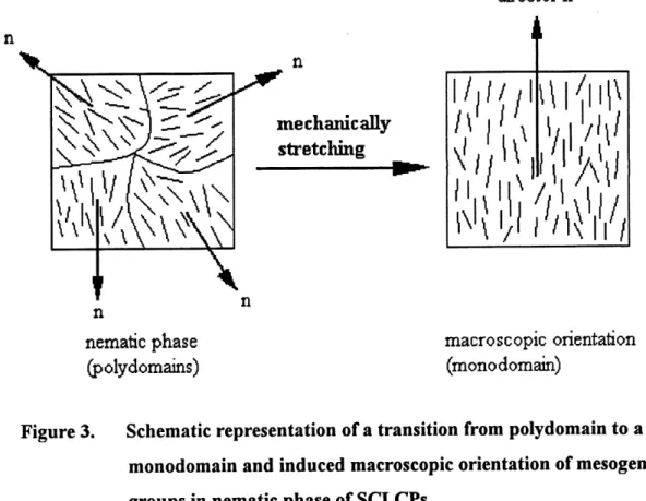
LC phases are intrinsically oriented microstructures, i.e., the orientational order of the mesogenic groups exists in local LC domains, whose directors are randomly aligned. In other words, a SCLCP sample, such as a solution-cast film, is isotropic over a macroscopic scale, and does not have anisotropic properties. This is the so-called polydomain structure, as
schematically depicted in Figure 3. When a polydomain-sample is subjected to the effects of
an external field, including magnetic, electric, surface and mechanical field, an alignment of the
LC domains can be induced, leading to a uniform orientation of the mesogenic groups along a
monodomain stmcture. The transition from a polydomain to a monodomain as a result of a mechanical stretching is schematically shown in Figure 3.
director n n n
mechanically
stretching
'iW
\Wl'
nnematic phase
(polydomains)
macro scopic orientation
(mono domain)
Figure 3. Schematic representation of a transition from polydomain to a monodomain and induced macroscopic orientation of mesogenic groups in nematic phase of SCLCPs.
From the technological point of view, the induction, control and manipulation of such a monodomain structure is of cmcial importance because having a monodomain structure is a
prerequisite for all main applications of SCLCPs. To this regard, it is of great interest to
develop new SCLCPs whose monodomain structure can easily be achieved and controlled.
With the research and development of the liquid crystalline polymer (LCP) materials, a large
number of SCLCPs, mostly based on poly(meth)acrylates and polysiloxanes, has been
prepared. In the past several years, much effort has been made to explore new LC polymeric
block and graft copolymers, and on the ion-containing SCLCPs which display mesophases where the ionic aggregates, characteristic of the ionomers, are present (9). Another system
showing a great potential is the side-chain liquid crystalline elastomers (SCLCEs) (10-12)
prepared by cross-linking SCLCPs. SCLCEs are attracting more and more attention since they allow a macroscopic and uniform orientation of the mesogenic groups to be achieved and controlled by a mechanical stretching.
In view of the great interest of developing new LC functional materials, in the present study
we have prepared and studied two novel systems based on SCLCPs. One is termed
inteq)enetratmg liquid crystalline polymer networks (ILCPNs) (13). The concept of
inteq^enetrating polymer networks (IPNs) is well known, and a considerable amount of studies on conventional polymers were reported (14). We are the first to extend the concept to LCPs. Here, an ILCPN is a combination of two liquid crystalline elastomers, or simply two LCPs in network forms, whose networks are physically interlocked. Since phase separation in
IPNs might be restricted to different extents by the cross-links, ILCPNs could offer new
possibilities of making specialty materials with finely divided phases or a dual phase continuity
which generally cannot be achieved by mixing two LCPs because of the immiscibility. The
other novel system is a graft copolymer with a SCLCP component grafted on a
styrene-butadiene-styrene (SB S) triblock copolymer (15). This graft copolymer system, which could
have a SCLCP content of as much as 52 wt%, exhibits very interesting and improved
properties as compared to the SBS/SCLCP blends, such as a homogeneous morphology and
higher mechanical strength. As also will be shown in this thesis, a uniform macroscopic orientation of the mesogenic groups of the SCLCP component in such graft copolymers can easily be induced by stretching their elastic films and, more interestingly, the monodomain structure can almost be totally preserved in a relaxed free standing film after a special thermal treatment process.
The whole research work described in this thesis includes two parts. The first part consists in synthesis and characterization of two new SCLCP-based systems, i.e., the interpenetrating networks and the graft copolymers as briefly mentioned above, and the orientation induction of the graft copolymers. The second part is composed of two separate projects of physical studies ofSCLCPs. In one, we have investigated the alignment ofnematic domains of a series of ion-containing SCLCPs, namely LC ionomers, under the effect of a mechanical stretching.
In the other project we have studied relaxation phenomena for a stretched SCLCP heating to
the vicinity of its phase transitions under strain. The presentation of those studies is organized as follows.
Chapter 1 describes the synthesis and characterization of sequential DLCPNs prepared through
1) the combination of two covalent networks, and 2) the combination of a non-covalent and a covalent network. Chapter 2 discusses our research on the graft copolymers, including the synthesis, characterization and orientation induction. Chapter 3 presents the results of the orientation studies on LC ionomers, while Chapter 4 is dedicated to the thermally-induced relaxation and reorientation behavior of stretched SCLCPs. Finally, a general conclusion is given. Throughout this study, the characterization of the samples was carried out with several techniques. These are Fourier-transform infrared (FTIR) spectroscopy (on a Bomen MB-102
FTIR), differential scanning calorimetry (DSC) (on a Perkin-Elmer DSC-7), optical polarizing
microscopy (on a Leitz DMP microscope equipped with an Instec hot stage), and, when
necessary, gel permeation chromatography (GPC) and nuclear magnetic resonance (NMR)
spectroscopy. The measurements of the molecular orientation, in terms of the orientation parameter, were performed through infrared dichroism. More details relative to each project will be given in the respective chapter.
CHAPTER 1
SYNTHESIS AND CHARACTERIZATION OF DVTERPENETRATCW LIQIHD
CRYSTALLINE POLYMER NETWORKS
1.1 Background
Interpenetrating polymer networks (IPNs) (14) are defined as a combination of two polymers
in network form, at least one of which is synthesized or cross-linked in the immediate presence of the other. IPNs exhibit varying degrees of phase separation, dependent principally
on the compatibility of the polymers. With highly incompatible polymers, their phase
separation occurs strongly. In cases where the polymers are more compatible, phase separation can be almost completely circumvented. In many ways, IPNs are related closely to
block copolymers. In the block copolymer systems, the length of the block determines the
size of the domains. Correspondingly, the link level (length of chain between
cross-links) plays a major role in determining the domain size of IPNs. Short block or chain
segments between cross-links both make for small domains under many conditions. IPNs represent one of the fastest growing fields in polymer science. Although most of these materials are phase separated, the presence of cross-links reduces the phase domain size and provides a method of controlling properties.
IPNs can be made in many different ways. According to the used different synthesis method
they can be classified as several types, among which the most important are sequential and
simultaneous IPNs. A sequential IPN is prepared by the following procedure: polymer
network-1 is made and swollen in the monomer II plus cross-Iinker, and then the monomer It
polymerization simultaneously in a mixture containing both monomers (or pre-polymers) plus cross-linkers.
Di Di Di Di Di
monomcr I•I •I
crosslinker I '\ ^potymerize
polymerize^
polymer network ID2D2D2D2D2
monomer IE•2 •2
crossUnker It swell in monomer H and crosslinker IEFigure 4. Basic synthesis method for sequential IPNs.
On the basis of the extensive investigations on IPNs formed from conventional non-liquid crystalline polymers, it has become clear for us to extend the concept of inteq)enetrating
networks to SCLCPs could bring new perspectives for the development of SCLCP-based
functional materials. Among the continuously increasing research activities on SCLCPs, the
greatest effort is still being made for the preparation of new polymers which, hopefully, would
find applications or meet the requirements for the development of specific electrooptic
devices. These studies essentially involve new synthesis and characterization methods, with
the synthesis methods often becoming more and more complicated. We think that it is of
considerable number of studies dedicated to polymer blends. The reason is that blending two or more polymers is an important way of making new materials. Now, it is well recognized that not only miscible blends but immiscible, phase-separated blends with controlled morphology can be valuable industrial materials. In the case of SCLCPs, and for polymer liquid crystals in general, few, if any, of them are miscible. Actually, the miscibility within
mesophases is still more difficult to achieve as a result of the additional long range ordering as
compared to conventional polymers (16). This means that blending two SCLCPs essentially
leads to no useful materials because of the severe phase separation with uncontrollable morphology. As already mentioned, interpenetrating two cross-linked conventional polymers is known as an effective way of restricting the phase separation by the cross-links, which often can result in microphases (tens of nanometers in size) like in block copolymers, or two continuous phases - a desirable morphology, or even the miscibility with one single phase for
the otherwise immiscible components (17); the interest of extending the concept of
interpenetrating networks to SCLCPs is obvious. Basically, an interpenetrating liquid
crystalline polymer networks (ILCPNs) makes it possible to combine or to bring together
intimately several SCLCPs. The potential of making new materials from ILCPNs is due to the
fact that they offer a broad spectrum of stmctural possibilities with varying degrees of
miscibility and changing interfaces. There are two basic beneficial situations that can be
expected. If the miscibility is induced between two SCLCPs, changes in their mesophase
behavior, such as enhanced phase stability and induction of new mesophases, could be observed. On the other hand, if no miscibility is induced but the phase-separated system has a
controlled interface and morphology, the resulting stable ILCPNs as a single material could
combine the features of two SCLCPs. The latter situation is as desirable as the former since it can produce designed functional materials for which the two components should not be
miscible. A nice example is given by a recent study on the design of efficient photodiodes: an
interpenetrating network of two phase-separated semi-conducting polymers having different electron affinities and ionization potentials was prepared to allow for efficient dissociation of
to illustrate the possibilities of LC-IPNs, we mention one example of designing this sort of
special material. For a film, sandwiched by two electrodes, of LC-IPNs formed from two
SCLCPs with different crossover frequencies at which the sign of their dielectric anisotropy
(As) changes, varying the frequency of the applied electric field can have the mesogens of
both SCLCPs aligned perpendicular to the film plane (As>0), or have the mesogens of
SCLCP-1 aligned perpendicularly while those of SCLCP-2 oriented parallel in the film plane
(As<0), or have the mesogens of both SCLCPs oriented parallel in the film plane.
As the first step of the strategy, developed in this laboratory, of exploring SCLCP-based
DLCPNs, the purpose of the present work is to study the feasibility of making sequential
ILCPNs, through the preparation of samples containing two cross-linked polyacrylate-based
SCLCPs, and demonstrate the possibility of modifying the mesophase transition behavior of
the polymers (13). Details on the synthesis and characterization are given below.
1.2 Synthesis of ELCPNs
A series of sequential ILCPNs based on two side-chain liquid crystalline polyacrylates were
prepared through the formation ofnetwork-2 inside a pre-formed network-1. The mesogenic and diacrylate monomers used in this study have the chemical stmctures shown below. It can be seen that monomer I and monomer II differ in the end group of the mesogenic moiety, OCH3 for the former and CN for the latter. Monomers I and II were synthesized according to
the methods in the literature (4), while monomer III was purchased from Aldrich.
Two types of the network-1 were used to prepare D..CPNS. The first type of network-1 was
prepared by co-polymerizing monomer I (or II) with the diacrylate monomer III
I CH2=CH-C02 fCHz h0-{0)~co2~(0/^° -CH3
H CH2=CH-C02 <CH^60^0)~C02-{OYCN
ffl CH2=CH-C02 fCHz h02C-CH=CH2
the resulting SCLCP was then partially hydrolyzed in a sodium hydroxide (NaOH) solution
giving rise to ion-containing SCLCPs, called LC ionomer. The LC ionomers have a network structure because of the ionic aggregates which act as cross-links. Once the network-1 was obtained, the technique of making ILCPNs was the same, that is, after swelling monomer II (or I) and monomer HE in a sample of 1, the polymerization in-siiu leads to network-2 interpenetrated with network-1. For the convenience of our discussion, the samples of
ELCPNs prepared from the two types of network-1 will be referred to as 'ILCPNs with two
covalent networks' and 'ILCPNs involving LC ionomers', respectively. Described below are
the details of the preparation ofDLCPNs.
1.2.1 DLCPNs with two covalent networks
The preparation was composed of two steps. First, a copolymerization ofmonomers I (or II) and in was performed in order to obtain the network-1. To do this, the following typical synthesis procedure was employed. A mixture of 1 g of monomer I, 0.0865 g of monomer HI, which corresponds to 20 mol % of the monomers, and 1 mol % of azobisisobutyronitrile (AIBN) as the initiator was dissolved in 5 ml chlorobenzene. After a rigorous stirring and a purge with nitrogen, the solution was heated to 60 °C for 18 hours for the polymerization. After removal of the solvent, the precipitated cross-linked polymer was washed five times through swelling in tetrahydrofuran (THF) in order to extract any un-reacted monomers and un-cross-linked polymers. The collected sample was finally dried under vacuum at 60 °C for 2
days. The diacrylate monomer was freshly distilled (under a vacuum of about 0.5 mmHg at 60 °C) before the reaction. It is clear that the cross-Hnking level of the network is determined by the concentration of the diacrylate monomer. The network-1 sample of the above example
will be denoted netOCH3(20%). The acronym indicates that the sample is a cross-linked
polymer prepared from monomer I (with the OCHs end unit) and the concentration of the
cross-linker used is 20 mol %.
Other cross-linked networks were prepared in this study. Besides netOCH3(20%), the
samples of netOCHs(10%) and netCN(10%) were utilized as the network-1 for the
preparation of ILCPNs. To facilitate comparisons as will be discussed later, other single networks from monomer II, such as netCN(20%), as well as the un-cross-linked homopolymers from monomers I and It, denoted PolyOCHs and PolyCN respectively, were also prepared.
After obtaining the network-1, the D-^CPNs could be prepared through the following
procedure. As a typical example, one piece of the netOCH3(20%) sample of 62 mg was
immersed in 1 ml of a chlorobenzene solution containing 200 mg of monomer It mixed with 10 mol % of monomer III and 1 mol % of AIBN, and swollen in a closed system at room temperature for overnight. Then, the swollen sample was separated from the remaining solution and placed into a small bottle. After circulating the nitrogen for 10 min, the bottle was sealed and placed into a thermostat oven at 60 C for the second polymerization in situ for 20 hours. After the reaction, five consecutive extractions were carried out using THF as the solvent. For every extraction the solid sample remained in the solvent for at least 4 hours.
The sample was finally dried in vacuum at 80 °C for two days. The obtained ILCPN sample
of the above example is denoted netOCH3(20%)-netCN(10%), where the monomer used for
1.2.2 ILCPNs involving LC ionomers
In this case, the ionomers prepared from PolyCN were used as the network-1. The
preparation of the PolyCN-based ionomers through a partial alkaline hydrolysis was
demonstrated in this laboratory (9). As a typical example, the ionomer containing 5.3 mol %
of the ionic groups was prepared through the following procedure: a 5 wt % PolyCN solution
was prepared using a solvent mixture of N, N-Dimethylformamide (DMF)/methanol (95/5,
v/v). The solution was stirred for overnight and then purged with nitrogen for 1 h before
addition of freshly prepared NaOH solution (concentration : 0.05 mol L ). After the
calculated amount ofNaOH was added in order to abtain an ionomer containing 5.3 mol % of the ionic groups, the reaction was performed at room temperature for 24 h, and then the mixture was precipitated into cold ether at ca. -25 °C. The solid was collected and dried. All the ionomers used in this study contain less than 10 mol % of the ionic groups. However, with the presence of the ionic aggregates, they can only be solubilized in very strong polar
solvents such as dimethyl sulphoxide (DMSO), and are no longer soluble in solvents like THF
and toluene. The samples used as network-1 for the preparation of ILCPNs were
netCNNa(2.5%), netCNNa(5.3%) and netCNNa(7.3%). From the acronym of the network-1,
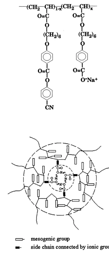
the sodium cation and the mole percentage of the COO'Na units are indicated. Obviously, the cross-link level is dependent on the content of the ionic groups. The determined structure of the ionomers (9) is shown below, and the cross-linking from the ionic aggregates is
schematically depicted in Figure 5.
The preparation procedure for the resulting ILCPNs using the above LC ionomers as the network-1 is basically the same as described above, and will not be repeated here. As monomer II was always used for network-2, the general acronym for the resulting ELCPNs is netCNNa-netCN.
—<CH2-CH)^CH2-CH^
o=c o=c
?
(^e
0=9.
0-Na+ mesogemc groupside chain connected by ionic group
1.2.3 Factors which determine the success of the preparation ofD^CPNs
Before discussing the characterization results, it should be mentioned that a number of unsuccessful attempts of preparing ILCPNs was made. From these synthesis experiences, several factors were found to be very important for obtaining ILCPNs successfully and should be considered carefully.
The first factor is the monomer concentration of the solution in which the network-1 was swollen by the mesogenic monomer with the solvent for subsequent polymerization to form the network-2 and get ILCPNs. In contrast to the preparation of a conventional sequential
IPN, for which the monomer swollen into the first network for subsequent polymerization is
generally a liquid, but in the present case the mesogenic monomer is a solid and must be dissolved in a solvent before being swollen into the network-I and polymerized. The monomer concentration should be high enough to expect a significant amount of the network-2 in the resulting D-^CPN, but should not be too high because the monomer molecules must be
kept in a mobile liquid phase during the polymerization. A number of attempts of
polymerizing ILCPNs shows that the range of monomer concentration was available from 10% to 20%, but the 20% monomer concentration was found to be the most appropriate.
The second factor is the choice of the solvent for subsequent polymerization to form the network-2. Because of the solvent evaporation as the polymerization processes, the reaction temperature and the choice of the solvent affect the results. The slower the speed of the solvent evaporation, the more favored the reaction of forming network-2. For this reason, although toluene is used as a common good solvent for the synthesis of polyacrylate, chlorobenzene is a better solvent than toluene in this polymerization because of its higher
The third factor is the reaction temperature which determines the rate ofpolymerization inside
the swollen samples. Although we do not know precisely how the cross-link level of network-2 changed with the advancement of the polymerization, it was likely that with a slow rate ofpolymerization a certain time was needed to reach an efFective cross-link level that was necessary to ensure gelation or physical interlocking between the two networks. As is known for IPNs, phase separation tends to occur once the second polymer is formed. If the polymerization in situ is not fast enough the early-formed linear and slightly cross-linked polymer chains could be phase-separated and extracted in the purification process; and in the meantime, the swollen sample becomes drier and drier, which prevents the polymerization from occurring at later time. This seems to explain some unsuccessful experiments by swelling a network-1 sample in a 10% (or less) monomer solution and using a lower reaction temperature of 55°C. 60°C was a better reaction temperature in preparing ILCPNs.
The fourth factor is also cmcial. It is the size of the network-1 sample for subsequent polymerization. Under the same conditions and with the same weight of the network-1 sample, e.g. 0.2 gram, it was necessary to have a single or a couple of big pieces which led to successful preparation ofILCPNs, while the attempts starting with fine granules (ca. <1 mm)
for swelling and polymerization ended in failure, or resulted in ILCPNs containing only a very
small amount of the network-2. This observation can be explained by a different evaporation rate of the solvent once the polymerization in-situ starts. The solvent evaporates much more rapidly with small swollen granules of the network-1 because of a much larger surface;
consequently the swollen sample loses most solvent and is dried shortly after being placed in
the oven, and no effective polymerization in-situ occurs.
Finally, the choice of the polymer as network-1 merits to be mentioned here. From a number
of attempts of making ILCPN samples, it was found that the samples of netOCHs with
different cross-linked levels were mostly suitable for the network-1 since they could absorb a
monomer I solution, making it possible to obtain D-^CPNs of netOCHs-netCN containing a large amount of netCN. This result was confirmed by comparing the sample of
netOCH3(10%)-netCN(20%) with netCN(10%)-netOCH3(20%), the former containing ca. 56
wt% netCN(20%) and the latter only having 23 wt% netOCH3(20%) (see Table 1).
1.3 Characterization of RiCPNs
In this section, the characterization of all synthesized ILCPN samples was described. The
compositions of ILCPNs were determined by using the FT-IR spectroscopy. All infrared
spectra were recorded at a resolution of 4 cm and from a total of 100 interferograms for
each spectrum. The phase transition behaviors of ILCPNs were investigated by using DSC
with a heating rate of 10 °C/min and a sample weight of ca. 20 mg. All presented
thermograms are from the second heating scan of the respective sample.
1.3.1 Determination of the compositions of ILCPNs samples
According to the preparation method, if the second polymerization in-situ did not result in a cross-linked polymer, i.e., the network-2, the repeated extraction would remove the second
SCLCP component. Simple calculations based on the change in the weight of the sample
allowed us to estimate the composition of the resulting ILCPNs, because subtracting the initial
network-1 weight from the weight of the ILCPNs yielded the weight of the network-2 present
in the sample. Nevertheless, in order to confirm the results obtained from the weight of the sample, we used infrared spectroscopy to determine the compositions of all obtained ILCPNs.
For all the ILCPNs with two covalent networks, netOCHs-netCN or netCN-netOCHs, the
presence ofnetCN is revealed by the characteristic -CN infrared band at 2230 cm which is
absent for netOCHs, and the content ofnetCN can easily be calculated from the absorbance of the 2230 cm'1 band (A.CN) relative to the absorbance of-C=0 band at 1734 cm (A.c=o) which
is contributed by both components. To do that, we prepared a series of blend samples with
different known compositions of two un-cross-linked polymers prepared from monomer I and monomer II, i.e., PolyOCHs and PolyCN, and measured the absorbance ratio ofA.cN to A.c=o
from the infrared spectra of all the blends, which are shown in Figure 6 for the region of
1450-2320 cm
-1 1734cm-1 Figure 6. 2230 cm.1v^
2200 2000 1800 1600Wavenumbers (cm )
Infrared spectra ofPolyOCHs, PoIyCN and their blend samples.
(1) PolyCN, (2) PolyOCH3/PoIyCN, 30/70, (3) PoIyOCH3/PolyCN,
50/50, (4) PolyOCHa/PolyCN, 70/30, (5) PoIyOCBb/PolyCN, 90/10
and (6) PolyOCHa
Plotting the content of PolyCN in the blend as a function of the absorbance ratio ACN/AC=O
yielded a straight line as shown in Figure 7. The curve fit equation is expressed as follows:
(PolyCN)%= 764.2 X
'•-CNl-c=o
100 r
Figure 7.
0.00 0.03 0.06 0.09 0.12 0.15
A /A
-CN -C=0
Content ofPoIyCN in the PolyCN/PolyOCEb blend vs the absorbance
ratio of A.CN/A.C=O.This equation is used to determine the content ofnetCN in the ILCPNs samples. The results obtained from the infrared analysis and from the weight calculation are listed in Table 2-1. It can be seen that both methods indicate similar compositions.
Table 1. Composition of ILCPNs with two covalent networks
Sample
The contents of the network-2 (%)
by I.R. by weight
netOCH3(20%)-netCN(20%)
netOCH3(20%)-netCN(10%)
netOCH3(10%)-netCN(20%)
49
52
56
50
51
58
netCN(10%)-netOCH3(20%)
23
22
In the case of the ELCPNs involving LC ionomers, i.e., netCNNa-netCN, the infrared analysis could not be made in the same way as described above, since both network components have
the CN absorption. However, it was found that a new band at 770 cm , shifted from the 762
cm band, was induced by the sodium salt group (-COO"Na+) in the ionomers and was sensitive to its concentration. This can easily be noticed from the infrared spectra of the ionomers used as network-1 and the non-ionic PolyCN presented in Figure 8.
,25 <u 0 .2 a n
A
^
0 M rfa < •15 .1 (D J2) (3) (4) 782 cm-1 770 cm-1 I ___|_ __A_ 900 850 800 750 700Wavenumbers (cm )
Figure 8. Infrared spectra ofPoIyCN and its ionomers: (1) netCNNa(7.3%),
(2) netCNNa(5.3%), (3) netCNNa(2.5%) and (4) PolyCN.
Now, the presence of netCN in the ILCPNs samples of netCNNa-netCN corresponds to a
dilution of the ionic groups and should be reflected by the 770 cm band with respect to the
762 cm band. Figure 9 gives an example of the infrared spectra in this region for a pure
ionomer, netCNNa(5.3%), the ILCPNs sample ofnetCNNa(5.3%)-netCN(20%) and the pure
.11-762 cm-1
900 850 800 750 700
Wavenumbers (cm )
Figure 9. Infrared spectra of (1) netCNNa(5.3%), (2)
netCNNa(5.3%)-netCN(20%) and (3) netCNNa(5.3%)-netCN(20%).
It is clear that the intensity of the 770 cm'1 band in netCNNa(5.3%)-netCN(20%) sample is
decreased as compared to netCNNa(5.3%) because of the dilution by netCN(20%), while the
pure netCN(20%) sample has no ionic groups and shows no band at 770 cm'1. Actually, on
the basis of the LC ionomers having different contents of the ionic groups, it was found that
the ratio of the absorbances of the 770 cm'1 band (^770) to the 762 cm'1 band (A 7^2) was
linearly proportional to the concentration of the ionic groups, and this allowed the content of
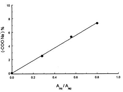
netCN in the ILCPNs to be estimated. The calibration line by plotting the content of sodium
salt COCWa % as a function of A^no/A^i is shown in Figure JO. The obtained curve fit
equation is expressed as follow:
^
0
0.0
A_/A_770 782
Figure 10. Linear reference curve of-COO'NaT content as a function of A-j-jo/A-jsi'
From this equation, the contents of the sodium salt for the netCNNa-netCN samples were calculated and compared with that of the pure netCNNa before the presence of the network-2.
The composition ofILCPNs involving LC ionomers can thus be determined and are shown in
Table 2, which are also confirmed by the weight calculation. For example, A^o/A-j^ of
netCNNa(5.3%)-netCN(20%) is 0.315, and a sodium salt content of 3.4% is obtained. So the
content ofnetCNNa is (3.4/5.3) x 100 = 64% and that ofnetCN thus is 36%.
Table 2. Composition ofDLCPNs involving LC ionomers
Sample
The contents of the network-2(%)
by I.R. by weight
netCNNa(7.3%)-netCN(20%)
netCNNa(5.3%)-netCN(20%)
netCNNa(2.5%)-netCN(20%)
28
36
25
30
37
27
1.3.2 Phase transitions of ILCPNs
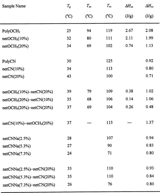
The phase transition behavior of all samples was investigated by means ofDSC. Summarized in Table 3 are the obtained data on the glass transition temperature (Tg), the smectic-nematic transition temperature (T,n), its transition enthalpy (AHsn\ the nematic-isotropic transition
temperature (Fn,) and the transition enthalpy (AHni).
First of all, some observations can be made on the single covalent networks as well as the ionomers based on the data in Table 3. Taking PolyOCHs for example. It displays a smectic and a nematic phase with a 7g at 25 °C, a F,n at 94 °C, and a Tn, at 119 °C. Its networks,
netOCHsOOVo) and netOCH3(20%), still exhibit both liquid crystalline phases, but the
transition temperatures and enthalpies are severely modified as a result of the presence of the covalent cross-links. Indeed, both Tsn and 7n, are shifted to lower temperatures, and the transition enthalpies are lowered. The effects become more important as the cross-link level increases. On the other hand, Tg of the networks increases with the cross-linking. Similar
observations can be made for PolyCN and its networks, netCN(10%) and netCN(20%). In
the case PolyCN-based ionomers, the increase in the content of the ionic groups, which corresponds to an increase in the number of the ionic aggregates and thus the cross-Iink level, also leads to a depression of the transition temperature; while 7g of the ionomers show a very slight decrease as compared to PolyCN. The disturbing effects of the cross-links leading to the decrease in the mesophase transition temperatures are well known, so is the effect of raising Tg by the covalent cross-links. The slight decrease in Tg for the ionomers can be explained in the following way. Generally, for the conventional ionomers, it is known that Tg
of ionomers will rise significantly by the presence of ionic aggregates as compared to the
corresponding polymer. But here the another effect due to the ionic interactions is that the partial hydrolysis reaction gives rise to a cleavage of some bulky, mesogenic groups, and the resulting smaller groups should have an effect of reducing the Tg of the polymer. Because of predomination of the latter effect the results lead to a decrease in Tg ofionomers.
Table 3. Phase transition temperatures and enthalpies of the samples.
Sample Name
PolyOCHs
netOCH3(10%)
netOCH3(20%)
PolyCN
netCN(10%)
netCN(20%)
netOCH3(10%)-netCN(20%)
netOCH3(20%)-netCN(10%)
netOCH3(20%)-netCN(20%)
T,
(°C)
25
32
34
30
34
43
39
35
37
T^(-C)
94
80
69
79
68
69
Tn,(°C)
119
Ill
102
125
113
100
109
106
104
AH^
(J/g)
2.67 2.11 0.74 0.38 0.14 0.26AHm
(J/g)
2.08 1.99 1.13 0.92 0.80 0.71 1.02 1.06 0.48netCN(10%)-netOCH3(20%) 37 — 115 — 1.37
netCNNa(2.5%) 28
netCNNa(5.3%) 27
netCNNa(7.3%) 24
netCNNa(2.5%)-netCN(20%) 33
netCNNa(5.3%)-netCN(20%) 35
netCNNa(7.3%)-netCN(20%) 26
107
90
71
110
110
76
0.94 0.83 0.80 0.93 0.84 0.801.3.2.1 ILCPNs with two covalent netrvorks
We expect to obtain ILCPNs with two interpenetrated cross-linked SCLCPs. If this is the
case, small or even microphases should be induced with a large interfacial region. In other words, more mesogenic groups belonging to the two SCLCP components could be brought into an intimate contact, resulting in a certain extent of miscibility. In principle, this can be reflected in the mesophase transitions of the ILCPNs as compared to the respective single networks. In order to reveal the features of ILCPNs, we first prepared and investigated
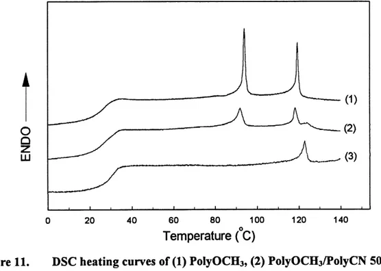
PolyOCHs/PolyCN blend samples. Figure 11 shows the DSC heating curves for PolyCN,
PolyOCHs and their 50/50 blend.
20 40 60 80 100
Temperature (C)
120 140
Figure 11. DSC heating curves of (1) PoIyOCH3, (2) PolyOCHa/PoIyCN 50/50 blend
and (3) PoIyCN.
The DSC curves of the blends are a simple addition of the curves ofPolyOCHs and PolyCN.
and nematic-isotropic transition of PolyOCHs, while the peak at 122 C characterizes the
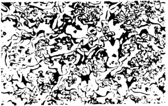
nematic-isotropic transition of PolyCN. Figure 12 shows a polarizing photomicrograph of
50/50 blend at 80 °C. Two distinct liquid crystalline textures are clearly seen in the phase-separated blend; the PolyCN phase exhibits a threaded nematic texture, whereas the smectic PolyOCHs displays a Schlieren texture with four bmshes. The sizes of the two phases are of the order of 50 ^m.
'^^:.
^^y
'{^-e^
±-^:.
Figure 12. Polarizing optical micrograph of the 50/50 blend of PolyOCHs
and PoIyCN at 80 °C. Magnification: 170X.
Now, we compare the results for ILCPNs and their respective single networks. First, an
interesting feature of ILCPNs can be revealed by comparing netOCH3(20%)-netCN(10%)
with netOCH3(20%) and netCN(10%), the two corresponding to pure polymer networks.
Their DSC curves are displayed in Figure 13. As compared with the un-cross-linked
polymers, netOCH3(20%) (curve 1) still exhibits both transitions, but as expected, owing to
the cross-linking effects, both Tsn and Tn, are shifted to lower temperatures, with Tsn = 69 °C and Tni =102 °C, and the transition peaks are broadened and the transition enthalpies lowered, whereas its Tg increases to 34 °C. The same observation can be made for netCN(10%) (curve
3) which has a Tn, lowered to 113 °C. Now, for the ILCPN sample,
netOCH3(20%)-netCN(10%) containing 52 wt% ofnetOCH3(20%)-netCN(10%) (curve 2), its Tg is almost unchanged with
respect to both pure networks, but only a very weak low-temperature transition seems to persist at temperatures around 68 C, and the drastic decrease of the transition enthalpy from
0.74 J/g for netOCH3(20%) to the estimated 0.14 J/g for the ILCPN sample obviously cannot
be accounted for only by the dilution effect arising from the presence of netCN which has no
smectic phase. This result clearly indicates much interaction between the mesogenic side
groups of both networks which leads to a severe perturbation effect on the smectic ordering
of netOCH3(20%). More interesting is the nematic-isotropic transition peak of the ILCPN
sample which appears at 106°C that is intermediate between Tni ofnetOCH3(20%) and that of
netCN, i.e., 4 C higher than the former and 7 °C lower than the latter. This change of the nematic-isotropic transition implies a single nematic phase formed by both mesogenic groups, or two nematic phases whose 7n, s approach each other. In one way or another, this can only
result from an intimate interlocking of both networks in the ILCPN sample.
A
Q
Q
LU 20 40 60 80 100 120 140Temperature (C)
Figure 13. DSC heating curves of (1) netOCH3(20%), (2) netOCH3(20%)-netCN(10%)
and (3) netCN(10%).
Strong effects were also observed for netOCH3(20%)-netCN(20%), an DXPN having a
higher network-2 density. Figure 14 shows the heating DSC curves of
netOCH3(20%)-netCN(20%) with its corresponding two pure networks, netOCH3(20%) and netOCH3(20%)-netCN(20%).
This ILCPN sample, containing 49 wt% of netCN(20%), has a Tg of 37 °C which is 3 °C
higher than Tg of the netOCH3(20%) and 6 °C lower than that of the netCN(20%). The
smectic-nematic transition peak of netOCHs (20%) was severely weakened in the ILCPN
sample. Interestingly, it is the apparently single nematic-isotropic transition peak which is higher than the transitions in both pure networks.
LU
100 120 140
Temperature (C)
Figure 14. DSC heating curves of (1) netOCH3(20%), (2) netOCH3(20%)-netCN(20%)
and (3) netCN(20%).
Investigations on the conventional IPNs (14) indicate that the domain sizes ofIPNs are mostly
determined by the cross-link levels, especially that of network-1. Figure 15 displays the DSC
netOCH3(10%)-netCN(20%) with netOCHsOOYo) and netCN(20%) reveals another solution.
Although the apparent low-temperature transition of ELCPN, appearing at 79 C, is also severely weakened, which indicates a strong interlocking of the two networks, some significant difference can be noted. The glass transition region is broadened, and the nematic-isotropic transition peak clearly is composed of two superimposed peaks at around 109 and 98 C, respectively. They apparently correspond to the peaks of the two pure networks. All
this indicates a lesser miscibility between the two components in this sample, which should
result in larger domain sizes. This is likely to be due to the lower cross-link level of
network-1 which restricts less efficiently the phase separation during the polymerization in-situ.
40 60 80 100 120 140
Temperature (C)
Figure 15. DSC heating curves of (1) netOCH3(10%), (2) netOCH3(10%)-netCN(20%)
and (3) netCN(20%).
As different from the above ILCPNs which combine a netOCHs sample as network-1 and a
netCN sample as network-2, the sample of netCN(10%)-netOCH3(20%) is made of
netCN(10%) as network-1 and netOCH3(20%) as network-2. The network-2 content of this
DLCPN, i.e., 22 wt % netOCH3(20%), is much lower than that of the above ILCPNs (ca. 50
wt %). From the DSC curves shown in Figure 16, it is seen that no smectic-nematic transition can be noticed for the ILCPN sample, and that the nematic-isotropic transition is a
little higher that those of pure networks.
20 40 60 80 100 120 140
Temperature (C)
Figure 16. DSC heating curves of (1) netCN(10%), (2) netCN(10%)-netOCH3(20%)
and netOCH3(20%).
7.3.2.2 ILCPNs involving LC ionomers
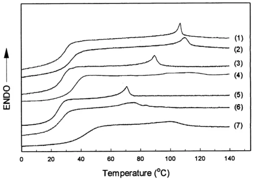
The DSC heating curves for the three LC ionomers used as network-1 and their D^CPNs with
netCN(20%) and the pure netCN(20%) are displayed in Figure 17 for comparison. In contrast
with the D-^CPNs of netOCHs-netCN, the obtained content of network-2 in these
ionomer-based ILCPNs is quite low (around 30 wt %). All the three ELCPNs were prepared by
120 140
Temperature (°C)
Figure 17. DSC heating curves of (1) netCNNa(2.5%), (2)
netCNNa(2.5%)-netCN(20%), (3) netCNNa(5.3%), (4) netCNNa(5.3%)-netCN(20%)
(5) netCNNa(7.3%), (6) netCNNa(7.3%)-netCN(20%) and
(7) netCN(20%).
In all cases, the ILCPNs sample has a higher Tg than that of the ionomer network-1, but lower
that that ofnetCN(20%). Interestingly, the glass transition region of each ILCPNs apparently
is not broadened. This intermediate Tg with an unchanged glass transition area is indicative of a certain degree of miscibility between the two network components. As for the nematic-isotropic transition, a higher and broader peak can be noticed for all ILCPNs as compared to the respective ionomer network-1. But, unlike the samples ofnetOCHs-netCN, the peak does not seem to be either intermediate between or an addition of the peaks of the two single
networks. Only in the case ofnetCNNa(7.3%)-netCN(20%) the peak position is intermediate.
These results suggest a strong interlocking between the two networks. In the case of
higher than those of both netCNNa and netCN(20%) could suggest that the actual cross-link
level of the network-2 in the ILCPNs samples is lower than that of the pure netCN(20%).
The unusual width of the transition peak, particularly for netCNNa(5.3%)-netCN(20%)
should reflect a heterogeneous stmcture throughout the sample.
Another observation also proves an intimate interaction between the two networks in the ILCPNs samples. The ionomer network with ionic aggregates as cross-links is thermoplastic
and can be dissolved in strong polar solvents like DMSO (9). Placing the D-^CPN sample in
DMSO, if there is no intimate interlocking between the two networks, most of the netCNNa
should be expected to dissolve in the solution and be extracted. We performed the experiment
with the sample ofnetCNNa(5.3%)-netCN(20%). In contrast to the pure ionomer sample, no
visible dissolution of the ILCPNs sample could be observed. After several hours of extraction
in DMSO, a small amount of netCNNa(5.3%) was extracted since the estimated content of
netCNNa(5.3%) in the extracted ILCPNs sample is 44 wt% instead of 63 wt% in the
un-extracted sample. This result implies a strong interlocking between the two networks which hinders the dissolution of the ionic network.
1.4 Conclusion
We have extended the concept of inteq)enetrating polymer networks to SCLCPs, giving rise to ILCPNs. For the first time, several polyacrylate-based sequential ILCPNs were successfully prepared through polymerization in-situ of a mesogenic monomer solution which is absorbed in a LC network made from another mesogenic monomer. Two types of
network-1 were utilized. These are either a covalently linked SCLCP or a non-covalently
cross-linked SCLCP, the latter being a thermoplastic, ion-containing SCLCP with ionic aggregates
acting as cross-links. We found that the success in preparing D..CPN samples was determined by a number of important factors, which includes the monomer concentration, the solvent
used for the polymerization in-situ, the reaction temperature, the size of the network-1 sample, and the choice of network-1.
As compared to single network samples, phase transitions in the obtained ILCPNs were
modified to different extents depending on the achieved miscibility between the two
components in the systems. We found that a first network of a greater cross-link level generally results in an ILCPN sample displaying a greater miscibility and, consequently, more profound effects on the phase transitions of the two components. This observation indicates that a greater cross-link level for the network-1 restricts more efficiently the phase separation as the second polymer is formed. Overall, the rate of gelation during the second polymerization relative to the rate of phase separation governs the extent of the phase mterpenetratmg.
More importantly, this study demonstrates the possibility of exploring a novel SCLCP-based
system. Indeed, it is expected that ILCPNs could combine the features of two different
SCLCPs into a single stable material, which opens a new route for the development of
CHAPTER!
GRAFTmG OF LIQUID CRYSTALUNE POLYMERS ON A
STyRENE-BUTADDENE-STORENE TRIBLOCK COPOLYMER AND
ORIENTATION INDUCTION
2.1 Background
There is an increasing interest in preparing block or graft copolymers containing a SCLCP.
They represent one of the most exciting new materials based on SCLCPs through the combination of the self-assembled morphology in the copolymers and the anisotropic features
arising from the liquid crystals. The synthesis method for the preparation ofLC block or graft
copolymers usually is very complex, generally involving the utilization of anionic polymerization. To date, one of the few successful systems is the styrene-SCLCP-styrene tri-block copolymer (19). The interest of the present study is twofold. Firstly, from the new-materials-making point of view, the purpose was to exploit a new and easy approach of making SCLCP-containing copolymers. It is a known industrial procedure to prepare styrene-butadiene graft copolymers by polymerizing the monomer of styrene in a solution with a
dissolved polybutadiene (PB) and resulting in polystyrene (PS) grafts on PB chains (20). By
employing this approach, we polymerized the monomers of SCLCPs in a solution with a
dissolved SB S tri-block copolymer (15), which is commercially available. As will be shown
below, the characterization results indicate the grafting of SCLCP onto the central PB block
leading to graft LC copolymer system.